Induction motor characteristics
AIM
1. How induction motor operation is similar to the clutch?
2. Calculate the starting time of a drive with the following parameters:
J=10 kg-m2,
T = 15 + 0.5wm
Tl=5+0.6ωm
3. A drive has following equations for motor and load torques:
Tm=(1+2ωm)
Tl= 3 √ωm
Obtain the equillibrium points and determine the stability.
4. Make a MATLAB script file which will plot speed-torque characteristics for frequency control method.
Study 1>
How induction motor operation is similar to clutch?
Induction motor
The stator and rotor are two essential parts of the motor. The stator is the stationary part and it carries the overlapping windings and the rotor carries the main or field winding. The windings of the stator are equally displaced from eachother by a phase angle of 120 degrees.
The induction motor is the single exicted motor which means the supply is applied to one part that is stator. when three phase supply is given to the stator, the rotating magnetic field produced on it. The torque induced on the conductor is known a s electrmagnetic torque.
Mechanical clutch
Clutch works on the principle of friction because when two rough surfaces cluth plates comes in contact with eachother. Then they become rotating as a single unit. the cluth is located between the engine and the gear box, mounted directly to the face of the engine's flywheel.
The cluth connects and disconnects two rotating shafts(drive shafts or line shafts), one shaft is typically attached to one engine (driving member) while the output shaft (the driven member) provides output power for work. If the engine is running with cluth engaged and the transmission in neutal, the engine spins the input shaft of the transmission, but no power is transmitted to the wheels,altough the gear box does not stop rotating during a gear change, there is no torque transmitted through it.
The output shaft of the gear box is permanently connected to the final drive, the wheels ans so both always rotate together. With the clutch disengaged the gear box input shaft is free to change its speed as the internal ratio is changed . any resulting difference in speed between the engine and the gear box is evened out as the clutch slips slightly during the reengagement.
The driving shaft and the driven shaft attached to the cluth are rotating at different speeds which cause a slip and cluth is used to lock and hold them or release them. The slip which is between the driving shaft and driven shaft is given by :W2 = W1 (1-s).
where, s = slip
W2 = speed of driven shaft
W1 = speed of driving shaft
From this figure we can say that the motor is only functional between syanchronous speed point and breakdown Torque point.
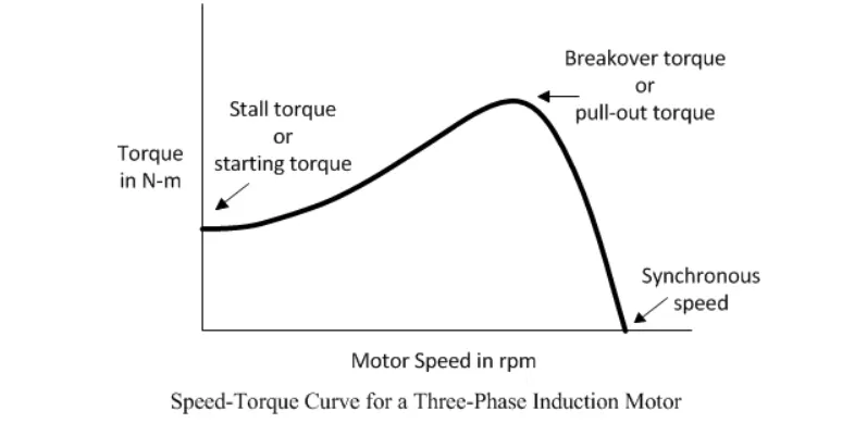
In the steady state condition of an induction motor, with the increase in speed, the motor torque should be less than the load torque. The speed of the rotor is always less than the rotating magnetic field. The rotor tries tor run at the speed of the rotor, but it slips away. So the motor can never run at the same speed as of rotating magnetic field. For this reson induction motor is also called as asynchronous motor. No relative motion occurs between the rotating magnetic field and conductors of the rotor.. Thus emf is not induced and no current devlops. The speed of the rotor is always less than the speed of rotating magnetic field. The equation for slip is :
Nr = Ns (1-s)
where, s = slip
Nr= speed of rotor
Ns= synchronous speed
Thus, the operation of mechanical clutch is similar to induction motor.
Study2.>
Calculate the starting time of a drive with the following parameters:
j=10kg-m^2
Tm=15+0.5wm
Ti=5+0.6wm
Solution:
Here' J= Moment of inertia od motor and load
Tm= Motor torque
Ti= Load torque
The steady state stability equation for an induction motor is given by,
Tm - Ti = J* dW/dT ......(1)
Where, dW =Change in angular velocity
dT =Change in time
As we know that , at steady state, the motor torque is equal to the load torque,
Ti=Tm
15+0.5w = 5+0.6w
0.1w = 10
w= 100rad/sec
The steady state speed for the induction motor is 100 rad/s
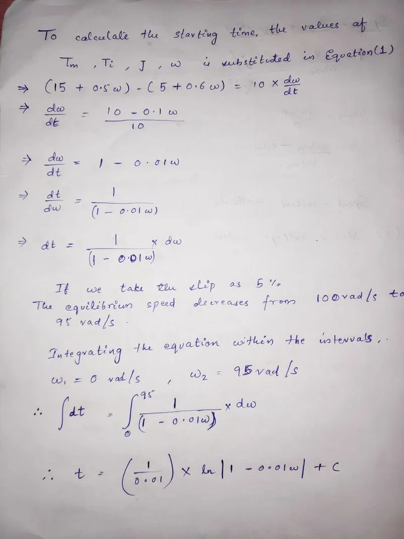
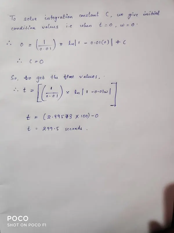
So the starting time of the induction motor(t) = 299.5 secs.
Study 3>
3-> A drive has following equations for motor and load torques:
Tm=(1+2ωm)
Tl= 3 √ωm
Obtain the equillibrium points and determine the stability.
Solution:
Stability of the motor is the is ability od the motor to drive the load. if it has enough power to start the drive then its caleed as stable whereas in induction motor , The difference of the change in load torque with respect to positive speed change and the change in motor torque with respect to speed change should be greater than zero in order to be stable.
dTl/dW-dTm/dw>0 ......"stable condition"
Given, Motor torque (Tm)=1+2wm
Load torque (Tl) = `sqrt3omegam`
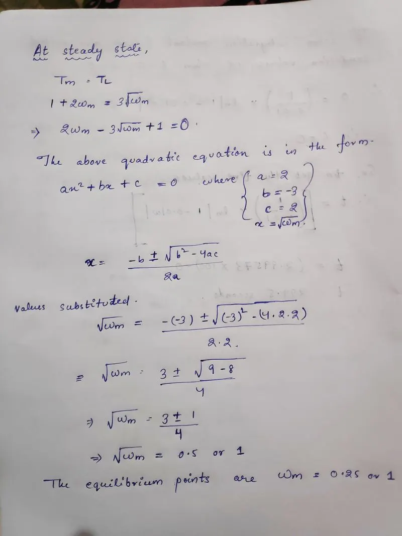
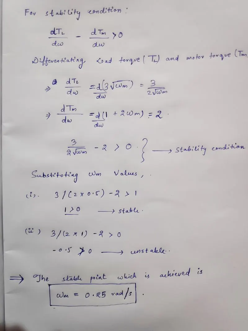
Thus stability is achieved at apoint where Wm=0.25rad/secs
Study 4>
Make a MATLAB script file which will plot speed-torque characteristics for frequency control method.
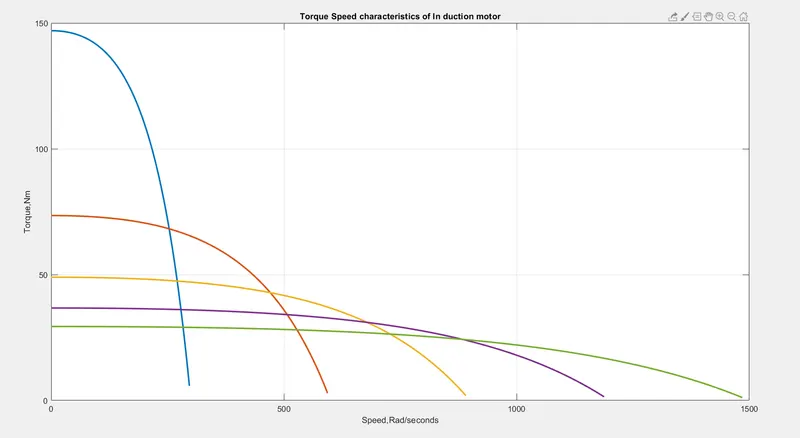
The frequency control method is a way in which the speed of an induction motor can be controlled in its operation. Varying the frequency will vary the speed od the magnetic field which is rotating. Different frequencies of operation will have different torque-speed characteristics. Each synchronous speed will correspond to a different motor speed and hence a different slip between itself and the motor speed. This in turn will result in different torques.
In matlab script, i used the data as
Rated frequency- 50Hz
Number of phases-3
Stator inductance x1=0.1ohms
Rotor inductance x2=0.1ohms
Stator resistance r1=0.3ohms
Rotor resistance r2=0.3ohms
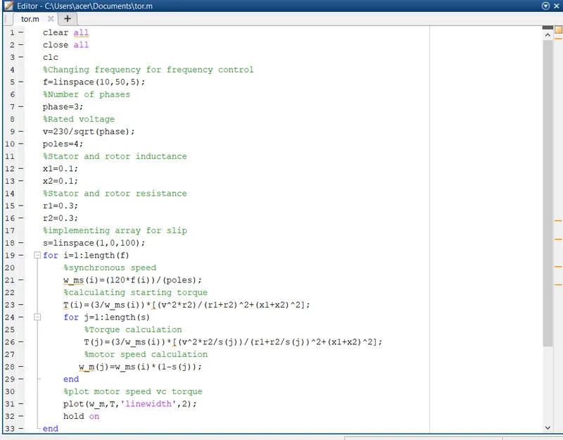
The synchronous speed is calculated using the formula Wms = 120*f/p
where, f=Frequency
p=Poles
A for loop is used in this calculation because we have an array of 5 frequency values. and each frequency will coresspond to a specific synchronous speed. So the for loop will range from 1 to 5 which will output 5 synchronous speeds. This loop is also used in torque calculations.
Formula to find torque T=3/wms*[(V^2*R2/s)/(R1+R2/s)^2+(x1+x2)^2]
The slip is given by the equation :
s = wms-wm/wms
Here we will use the synchronous speed values calculated from the first loop and the slip values from the slip array. Since this calculation is in the second for loop it also ranges from 1 to the length of the slip array . The second loop is terminated with the end command.
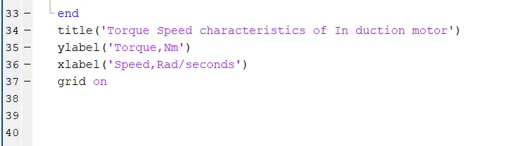
Now that we have the torque and motor speed values, plot command is used to plot the torque on yaxis and motor speed on x axis. Hold on command is used to so that each of 5 torque-speed characteristics in the same figure.
OUTPUT: