Induction motor characteristic 2
AIM: To study the induction motor using these objectives
OBJECTIVES:
- Discuss the equivalent circuit network of induction motor MATLAB model
- 3 phase, 50 Hz induction motor, represented by equivalent circuit constants X1 = X2 = 0.1 ohms and R1 = R2 = 0.2 ohms is operated at half of rated voltage and frequency. Calculate the ratio of starting torque at half voltage & frequency to rated values.
- Make a comparison of square wave inverter output voltage with sine modulated one.
OBJECTIVE 1: Discuss the equivalent circuit network of the induction motor MATLAB model.
The Simplified Induction Motor block represents the electrical and torque characteristics of an induction motor powered by an ideal AC supply. The following figure shows the equivalent circuit model of the Simplified Induction Motor block.
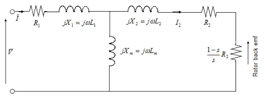
In the figure:
-
R1 is the stator resistance.
-
R2 is the rotor resistance with respect to the stator.
-
L1 is the stator inductance.
-
L2 is the rotor inductance with respect to the stator.
-
Lm is magnetizing inductance.
-
s is the rotor slip.
-
V and I are the sinusoidal supply voltage and current phasors.
Working Principle
An induction motor consists of a stationary component called the stator and a rotary component called the rotor. The stator consists of 3 coil winding supplied with 3 phase AC power which is wound around stacks of thin, highly permeable lamination in a cast iron or steel frame. Charging the frequency of the 3 phase supply power supply will generate a rotating magnetic field that interacts with the rotor via electromagnetic. induction. But now that the rotor is a current-carrying conductor in the rotating magnetic field, it will experience an electromagnetic force producing a torque via the motor effect.
Since an emf is induced in the rotor there will be a current flowing through it and this is denoted as I2
The inductor emf in the rotor as a result of electromagnetic induction is also referred to as back emf because it acts in the opposite direction to the direction of the 3 phase voltage across the coil winding in the stator.
The magnetic inductance, Lm is required at the air gap because across it is the boundary between the stator and the rotor. The stator will produce the rotary magnetic field and it needs to cross the sir gap to interact with the rotor to excite it to produce a torque. So the magnetizing inductance Lm is needed to cross this air gap.
Xm, X1, and X2 all represent reactance values. Reactance is a form of opposition that electronic components exhibit to the passage of current through the, due to their capacitance or inductance properties.
Operation:
The speed of the rotating magnetic field is also known as the synchronous speed and it is dependent on the frequency of the 3 phase power supply and the number of poles of the induction motor. So the frequency of the 3 phase power supply is proportional to the synchronous speed and also the motor speed.
The synchronous speed is determined by the formula below
`ω_ms = (120*f)/p`
where
Frequency of the 3 phase AC power supply - f
Number of poles -p
This synchronous speed needs to be greater than the motor speed because if the synchronous speed is greater than the rotor speed, there will be an interaction between the magnetic field and the rotor causing it to experience the electromagnetic force thus producing the torque. The slip is basically the phase difference between the synchronous speed and the rotor speed.
The slip varies between 0 and 1 and it's a maximum when the rotor speed is equal to the synchronous speed. In the former case, there will be no torque because there will be no interaction between the rotating magnetic field and the rotor. In the latter case, this is referred to as the starting torque and this is the highest torque that is produced by the induction motor.
For this model the slip is mathematically expressed in terms of the motor speed the number of poles and the frequency of the 3 phase power supply as so:
`s = 1- ( ω_m *p)/f`
where
motor speed - `ω`
synchronous speed - `ω_ms`
motor speed - `ω_m`
The torque that is produced by the rotor of the induction motor can be expressed mathematically as so:
`T = (n*p*R_2)/(s*f) *(V_rms^2)/((R_1+R_2+(1-s)/s)^2+(X_1+X_2)^2`
where
number of phases - n
Stator Inductance - X1
Rotor inductance - X2
Root mean square voltage - `V_rms`
The block can be modified in terms of the parameter mentioned below the equivalent circuit model or in terms of the motor rating. From the block, we can see that there are 2 mechanical ports, C and R. When the block is used in a simulation, positive torque is produced acting from those ports.
The block also has 2 thermal ports, one for each winding, and they are mainly used to simulate the copper resistance losses that occur which are in the form of heat energy. To see these ports we need to right-click on the block and from the option select Simscape then Block choice and then show thermal port.
While the simplified induction motor block can model the torque-speed characteristic of an induction motor there is still some limation that it has. For instance, it does not model the starting mechanism for a single-phase induction motor. Another limitation is that if that block is modeled in terms of the motor rating parameter then the equivalent circuit model parameters are derived by assuming that the magnetizing inductance term, Lm is negligible. Hence the effect of the magnetizing inductance term will not be included in the simulation.
OBJECTIVES - 2 3 phase, 50 Hz induction motor, represented by equivalent circuit constants X1 = X2 = 0.1 ohms and R1 = R2 = 0.2 ohms is operated at half of rated voltage and frequency. Calculate the ratio of starting torque at half voltage & frequency to rated values.
Solution-
Torque Speed relation of Induction motor is,
`T = [(n . R_2)/(s. ω_s)]*[(V^2)/((R_1 + (R_2)/s)^2+(X1+X2)^2]]`
The motor reaches starting torque and steady-state speed will occur and it transfers 100% efficiently as there is no related slip in the stable region. Slip reaches a maximum value of 1. So, torque - Speed relation of induction motor equation becomes,
`T = [(n . R_2)/(ω_s)]*[(V^2)/((R_1 + R_2)^2+(X1+X2)^2]]`
where,
Synchronous Speed for full rated frequency,
N1 =(120*F)/p
N1 = (120*50)/p
N1=6000/p
So,
`ω_s1 = (2*pi * N1)/60`
`ω_s1 = (2*3.14*6000)/(60*p)`
`ω_s1 = 628/p`
Synchronous speed for half rated frequency
N1 =(120*f/2)/p
N1 = (120*25)/p
N1=3000/p
So,
`ω_s1 = (2*pi * N1)/60`
`ω_s1 = (2*3.14*3000)/(60*p)`
`ω_s1 = 314/p`
Case (I) - Starting torque at rated voltage and frequency
`T1 = [(n*R2)/(ω_s1)]*[(V^2)/((R1 +R2)^2+(X1+X2)^2)]`
`T1 = [(3*0.2)/(ω_s1)]*[(V^2)/((0.2 +0.2)^2+(0.1+0.1)^2)]`
`T1 = [0.6/ (ω_s1)]* [(V^2)/0.2]`
`T1=3*(V^2)/(ω_s1)`
sub ws1 value in the above eqn we get
`T1 = 3 * (V^2/((628/p)))`
`T1 = (3*V^2*p)/628`
`T1 = (4.77*10^-3)*(V^2*p)`...........................(1)
Case (II) - Starting torque at rated voltage and frequency
`T1 = [(n*R2)/(ω_s2)]*[[(V/2)^2)/((R1 +R2)^2+(X1+X2)^2)]`
`T1 = [(3*0.2)/(ω_s2)]*[[(V/2)^2)/((0.2 +0.2)^2+(0.1+0.1)^2)]`
`T1 = [0.6/ (ω_s2)]* [[(V/4))/0.2]`
`T1=0.75*(V^2)/(ω_s2)`
sub ws1 value in the above eqn we get
`T1 = 0.75* (V^2/((314/p)))`
`T1 = (0.75*V^2*p)/314`
`T1 = (2.38*10^-3)*(V^2*p)`............................(2)
By dividing eqn(2) by eqn(1)
`(T2)/(T1)= ((2.38*10^-3)*(V^2*p))/((4.77*10^-3)*(V^2*p)`
`(T2)/(T1) = 0.5`
Result:
The ratio of starting torque at half voltage and frequency to rated value is 0.5
OBJECTIVE - 3 Make a comparison of square wave inverter output voltage with sine modulated one.
Comparison of square waves and sine modulated waves
| List of features | square waves | Sine waves |
| Describe | A square wave is a non-sinusoidal periodic waveform in which the amplitude alternates at a steady frequency between a fixed minimum and maximum values with the same duration at minimum and maximum. | A sine wave or sinusoid is a mathematical curve that describes a smooth periodic oscillation. |
| Output waveform | The output waveform of the voltage from this inverter is a square wave. | This is the major advantage of this inverter because all the appliances that we use are designed for this sine wave. |
| Support Appliances | Square wave inverters are usually used to support the motor alone. | sine wave inverters are used to support household appliances. |
| Overall safety level | Square wave inverters are less reliable and also unsafe to use for appliances. | Sine inverters are highly safe to use. |
| Noise Interference | Square wave inverters produce a very loud noise when used. | Sine wave inverters produce normal sound only. |
| Cost | The cost of this inverter is very low but the application is very rare. | This type of inverter is more expensive but widely used in residential and commercial applications. |
CONCLUSION:
We have successfully discussed the equivalent circuit network of induction motors. Completed calculation of the ratio of starting torque at half voltage and frequency to rated values. compare different types of inverter circuits and their output voltage.