Independent Research Project
Design and Analysis of Leaf spring Using Static structural Ansys
Computer-aided designing (CAD) is being widely used in different industries for product testing and manufacturing, this consist of the design and analysis of leaf spring using ANSYS Workbench where a Static structural tool has been used.
Leaf springs are used in heavy-load vehicles where the load is much larger than in passenger vehicles, they are used in vehicles which are limited to varying cycles stress to millions thus eventually leading to failure of fatigue. High elastic material springs are used which possess maximum strength and fatigue effects. Weight reduction is one of the major concerns while designing a vehicle as it helps in design optimization and fuel economy.
Four-layer leaf spring with full length leaf with conventional Structural steel has used and it was compared with Composite materials of Annealed Stainless steel and Carbon steel. After analysing, it is found Composite materials of Annealed Stainless steel and Carbon steel is better in strength and lighter in weight in contrast with Structural steel leaf spring.
Introduction
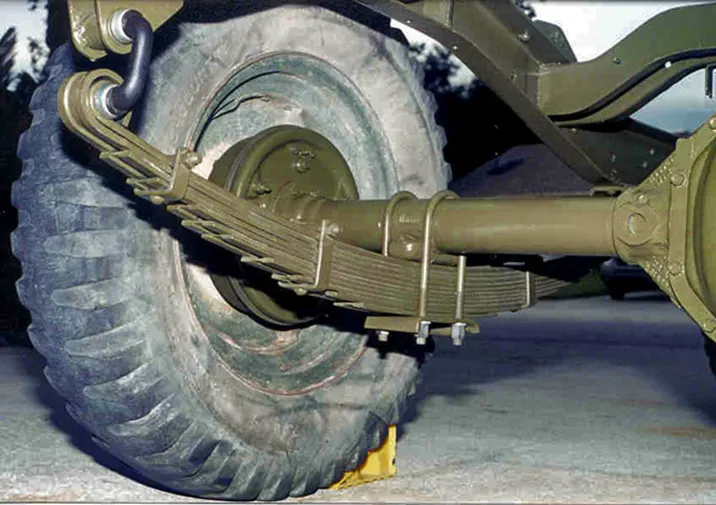
Leaf springs are suspension system used in vehicles. They were originally called carriage or laminated springs. It is made of an arc shape slender piece of steel that is stacked with the same material in smaller sizes and bolted together creating a reinforced bow-like item. A leaf spring works on the principle of bending. When the load is applied at the ends bending occurs. Naturally, the structure opposes bending. This results in a reaction force which opposes the load applied. Thereby we get the spring property of the leaf spring.
The overall purpose of leaf spring is to provide support to a vehicle and to provide a smoother ride absorbing any bumps or shocks from potholes on the road are track. Leaf springs are also used to locate the axle and control the height at which the vehicle rides and helps keep the tyres aligned on the road.
Leaf springs are a basic form of suspension made up of layers of steel of varying sizes sandwiched one upon the other. Most leaf spring setups are formed into an elliptical shape through the use of spring steel which has properties that allow it to flex as pressure is added at either end but then return to its original position through a damping process. The steel is generally cut into rectangular sections and then once held together by metal clips at either end and a large bolt through the centre of the leaf. It is then mounted to the axle of the vehicle using large U-bolts.
Advantages
The advantages of leaf springs are that due to the sheer amount of metal layered together, leaf springs offer a large amount of support between the wheel, axles and the vehicle's chassis. They can take huge vertical loads being applied to them due to their tight-knit structure, hence why heavy-duty industries still use them. Vertical loading is also distributed throughout the length of the leaf spring rather than acutely through a small spring and damper. Leaf springs are being used for a very long time in vehicles especially in commercial vehicles due to their high strength-to-weight ratio, it is being used by various industries. Springs has the ability to store and absorb more amount of strain energy and ensure a comfortable suspension system.
Disadvantages
A few disadvantages of leaf springs are that they allow very few directions of motion and are only designed to move vertically, while a spring and damper combination can be manipulated into a much larger range of motion. Leaf springs are firmly clamped together and bolted to the chassis as well as clip to the axle, thus giving little scope for any other direction of motion or suspension in place.
Objective
The main objectives of this simulation are: -
To find out and compare the Total deformation, directional deformation, Equivalent stress and Equivalent elastic strain generated at the Leaf springs of different materials like Structural steel, annealed stainless steel and annealed Carbon steel
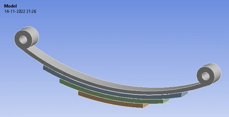
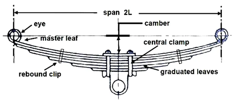
CAD Model of Leaf spring and its dimensions
|
Leaf Spring Part |
Radius |
Vertical Distance |
|
Eye Outer part |
3.5 mm |
|
|
Eye Inner Part |
1.7 mm |
|
|
Master Leaf |
90 mm – 92 mm |
2 mm |
|
Graduated Leaf 1 |
96 mm – 98 mm |
2 mm |
|
Graduated Leaf 2 |
100 mm – 102 mm |
2 mm |
|
Bottom Leaf |
102 mm – 104 mm |
2 mm |
|
Width of Leaf |
7 mm |
Material Properties
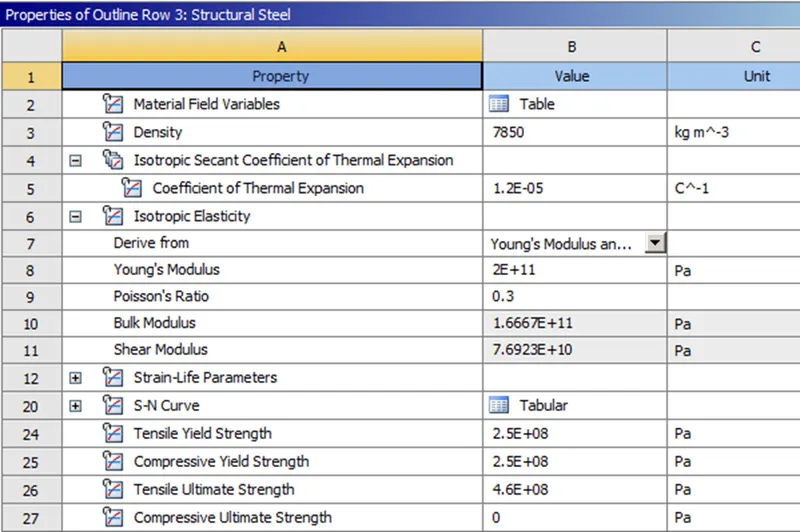
The materials for the leaf springs are taken for 2 cases and compared with Conventional Structural steel with Composite annealed 316 Stainless steel and annealed 1020 Carbon steel.
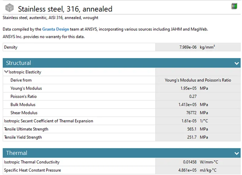
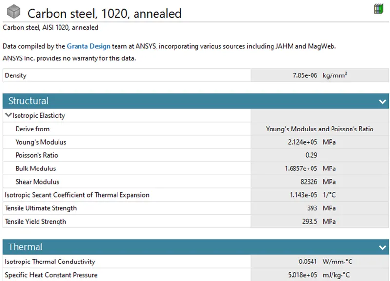
Case 1: Leaf Springs with all materials as Structural steel
Here the main intent is to demonstrate the boundary conditions and the loading of the leaf spring, because the whole assembly of the leaf spring is simplified to a single part.
It can be observed from the behaviour animation of the leaf spring that one end of the leaf spring is constrained in translation in all the 3 directions and allowed to rotate along the axis of the cylindrical surface/eye whereas on another end of the cylindrical surface/eye is allowed to translate in the X – direction.
So How this Boundary condition can be Accomplished?
As I discussed earlier the whole assembly of the leaf spring is considered as a single part for our simplicity because we have made intent that as to demonstrate the boundary conditions and loading for the leaf spring.
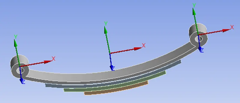
Leaf spring has two eye ends, to define the boundary condition at each of the ends, let us define the respective Cartesian Coordinate system.
Pick on the Coordinate system in the outline tree, Right-click – Pick on insert – Pick on Coordinate system – Right click on New Coordinate system – Pick on Rename – rename it as CSO-01.
To define this Coordinate system a Geometrical reference is required, so pick on the Geometry in the details of coordinate system box and ensure that the Surface is selected in the Selection filter, pick on the cylindrical surface/eye, pick on Apply to confirm the Geometry Selection. It can be observed from the type of the coordinate system as Cartesian.
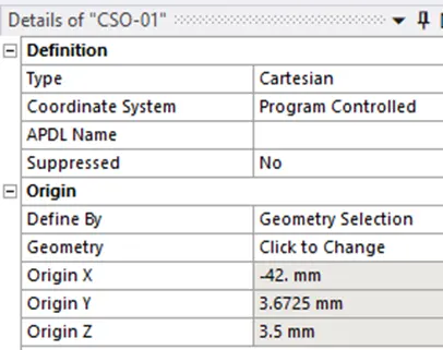
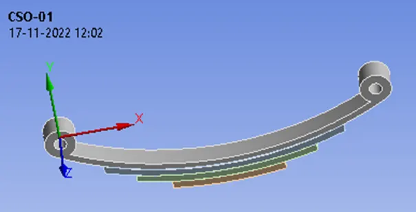
Now Right click on CSO-01 – pick on duplicate – rename this new coordinate system as CS0-02, the geometry of the new coordinate system is needed to be replaced by the right end of the eye/cylindrical surface of the leaf spring, pick on the Surface and Apply.
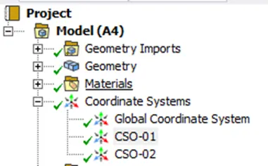
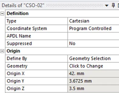
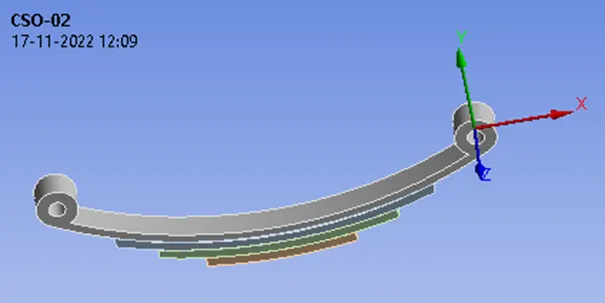
So currently we have 3 different coordinate systems, the first coordinate system is the global coordinate system and also different coordinate systems named CS0-01 and CSO-02, once the coordinate systems are defined let us proceed to define the boundary conditions for the leaf.
Boundary Condition
Remote Displacement 1
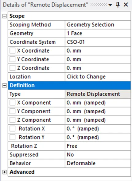
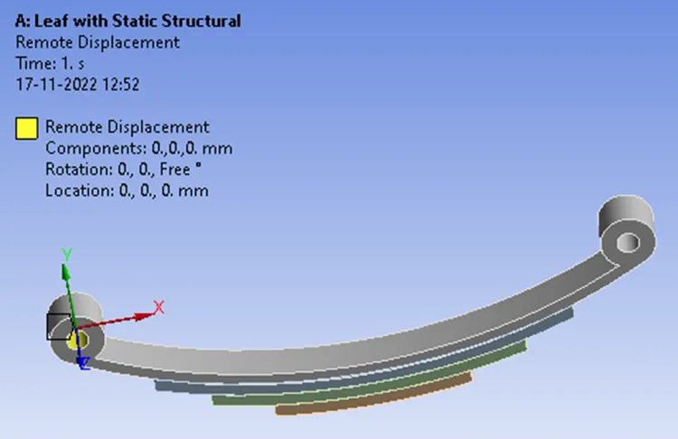
Right-click on Static structural – pick on insert – Remote displacement. Under the geometry – pick on the first cylindrical surface – pick on Apply.
Observe that the coordinate system should be selected as CSO-01 and the X – Coordinate 0. mm, Y – Coordinate 0. mm, and Z – Coordinate 0. mm, should be made zero for this particular remote displacement because we are defining the remote displacement for the highlighted surface with respect to the new coordinate system hence the coordinates should be 0. mm, 0. mm, 0. mm.
As we discussed earlier based on the cognizable guessing of the simulation this particular cylindrical surface/eye end should be restricted in all the directions for Translation, hence the translational degrees of freedom should be constantly zero for X – Component 0. mm (ramped), Y – Component 0. mm (ramped), Z – Component 0. mm (ramped).
But as for the rotation is concerned with the Z-Axis the body should be free to rotate or the highlighted face should be free to rotate, but it shouldn’t be allowed to rotate along the X-Axis and Y-Axis hence, the X – Axis and Y – Axis should be constantly zero, so Rotation X 0. ° (ramped), Rotation Y 0. ° (ramped), Rotation Z free.
Remote Displacement 2
Once the boundary condition is defined for the first end let us proceed to define the boundary condition for the second end.
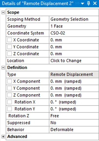
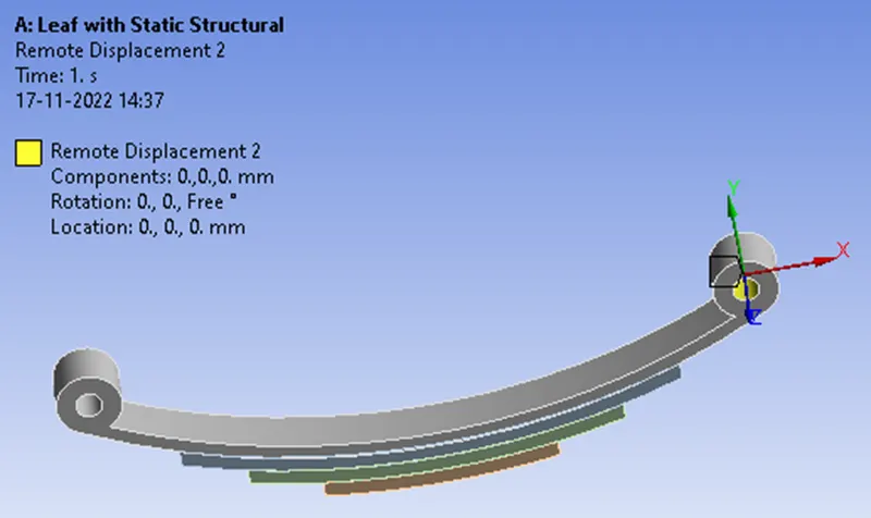
So right-click on the Static structural, pick on insert and select Remote displacement, under the geometry selection make sure that the surface is selected on the selection filter, and select this particular cylindrical surface and pick on apply. Similar to the earlier case the location of the remote displacement should be zero in the X – Coordinate 0. mm, Y – Coordinate 0. mm and Z – Coordinate 0. mm with respect to the coordinate system CSO-02.
The translational degrees of freedom should be defined in such a way that this particular second end/eye/Cylindrical surface should be set free to translate along the X – Direction hence, X – Component free, Y – Component 0. mm (ramped), Z – Component 0. mm (ramped). As far as the Rotational degrees of freedom is concerned similar to the previous case the cylindrical surface should be allowed to rotate along Z – Axis with respect to the coordinate system CSO-02 and should not be allowed to rotate along the X and Y axis hence, Rotation X – 0. ° (ramped), Rotation Y – 0. ° (ramped), Rotation Z – free.
Once the remote displacement for both ends is defined, let us apply the Displacement Constraints for the leaf spring to deform the whole body.
Constraints
Displacement
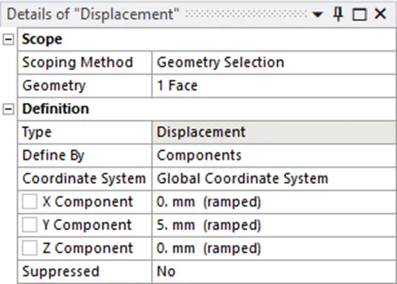
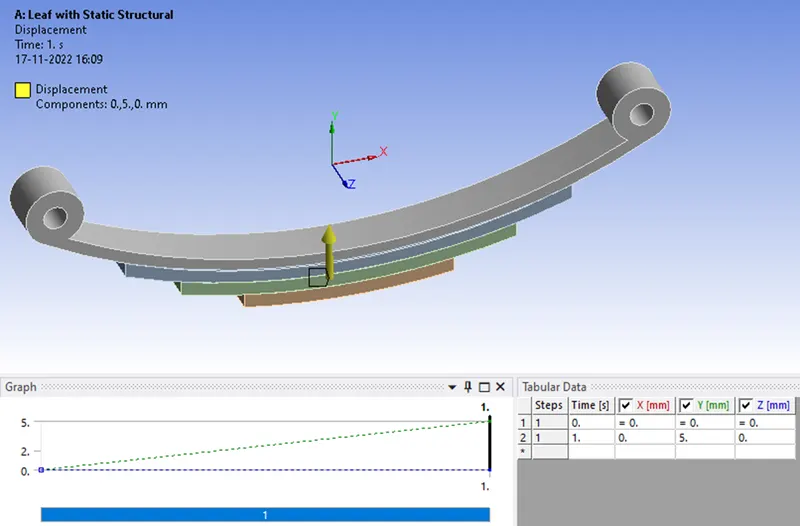
Right-click on Static structural, pick on insert – Displacement, select the bottom face, and pick on Apply on the Geometry, it should be defined by the Y displacement of 5 mm with respect to the Global coordinate system, and also observe that the coordinate system as it is Global and X – Component be 0. mm (ramped), Y – Component be 5.mm, Z – Component be 0. mm (ramped) so at this point in time, we have defined the boundary condition and the Loading.
Fixed Support
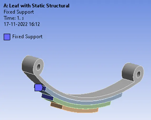
Since the Master leaf spring is constrained in all translational directions and allowed to rotate along the axis of the cylindrical surface whereas the graduated leaves are fixed in their position when the loading is said to act according to the global coordinate system.
Meshing
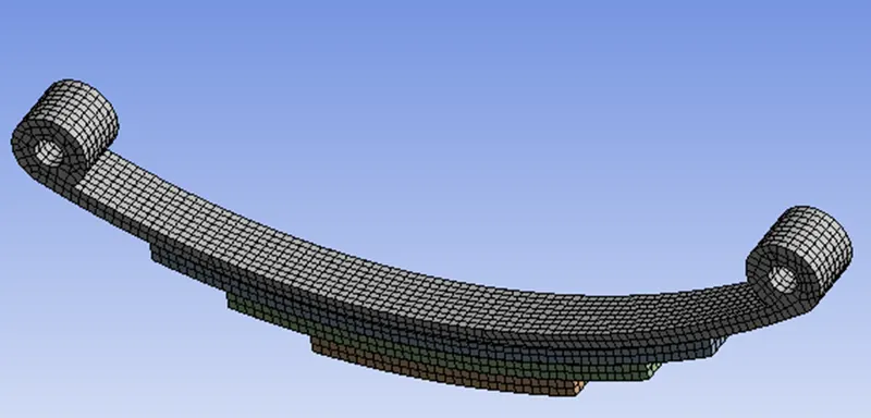
It is time to define the mesh, so click on the mesh, and select all the faces that should be sized with the Element size of 1 mm hence make sure that the surface is selected in the selection filter right click on the screen pick on select all, this is going to select the surfaces of the leaf spring and click on Apply. Now Click on Mesh – Generate mesh.
Mesh metric: Element Quality
The Element quality option provides a composite quality metric that ranges between 0 and 1 and this metric is based on the ratio of the volume (or area) to the square of the edge length.
So, a Value of 1 indicates a perfect cube or square or triangle or hexagon or quad while a Value of 0 indicates that the element has a zero or negative volume
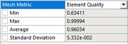
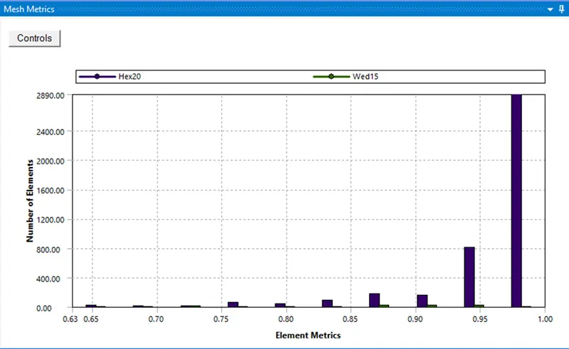
Let us proceed with the solution to the problem, once the behaviour was predicted to be accurate we can proceed with determining or evaluating the other results.
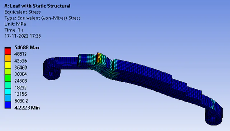
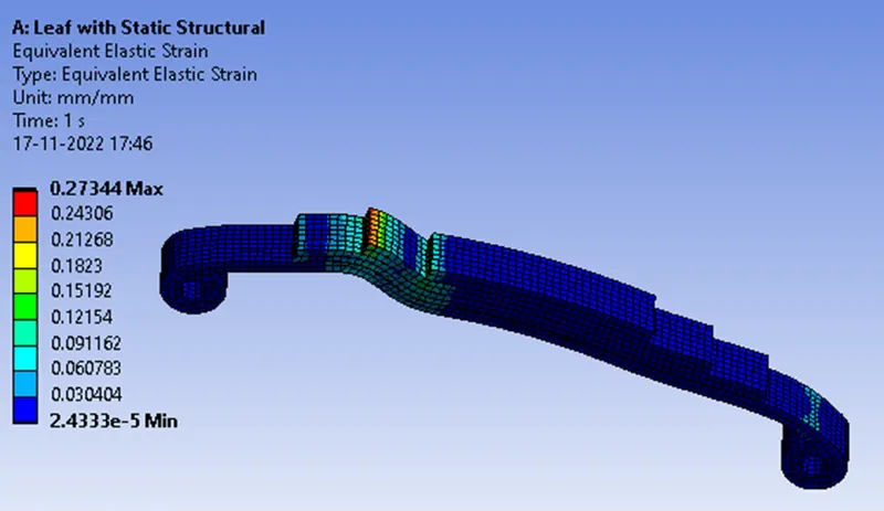
Simulation results For Case 1 With Material Structural Steel
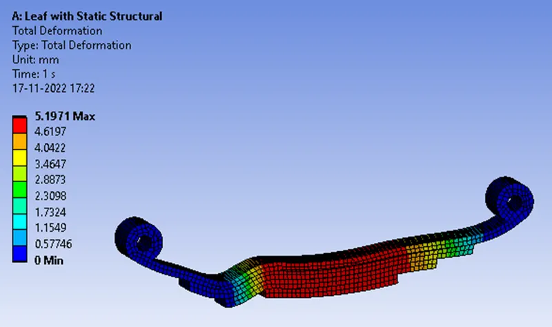
Total Deformation
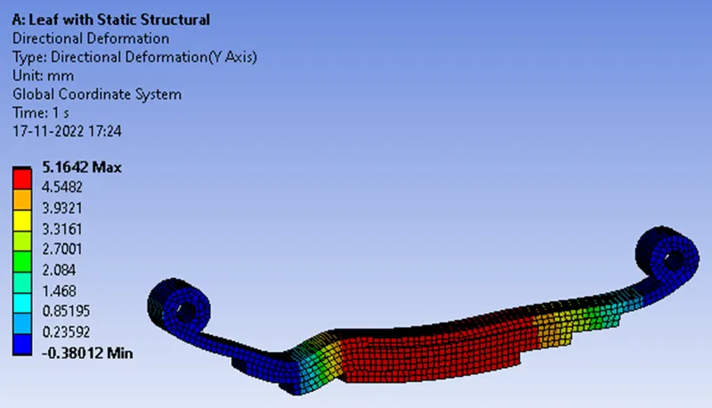
Directional Deformation Along Y-Axis
Equivalent stress
Equivalent elastic strain
Case 2 with materials as annealed 316 Stainless steel and an annealed 1020 Carbon steel
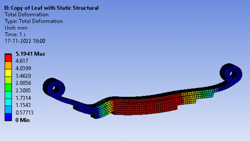
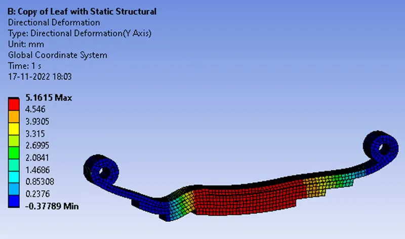
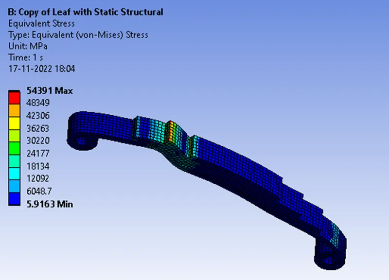
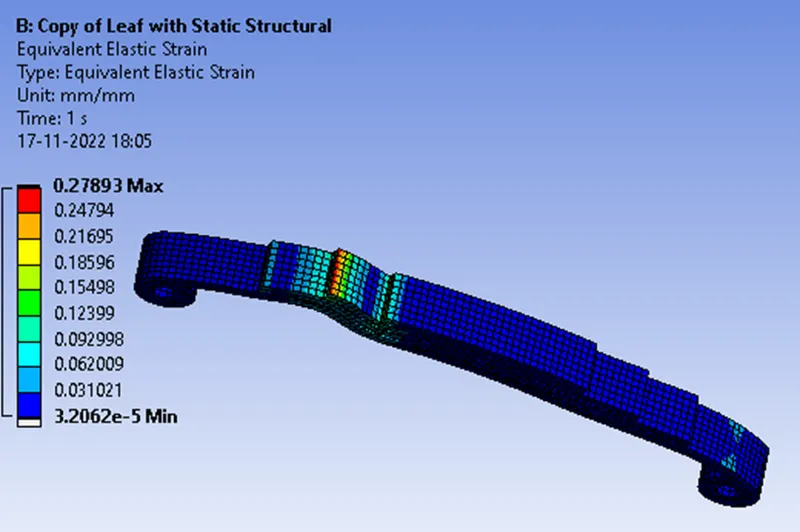
Here for case 2 similar boundary conditions and Constraints are applied as in case 1 and for the master leaf and the first graduated leaf annealed 1020 carbon steel has used and for graduated leaves, 3 and 4 annealed 316 stainless steel has used, hence the following simulation results has obtained.
Total deformation
Directional Deformation along Y-Axis
Equivalent stress
Equivalent elastic strain
Concluding result
|
Analysis for |
Total deformation mm |
Directional deformation along Y-Axis mm |
Equivalent stress MPa max |
Equivalent elastic strain MPa max |
|
Case 1: using Structural steel as the material |
5.1971 |
5.1642 |
54688 |
0.27344 |
|
Case 2: using Composite materials of annealed 316 stainless steel and annealed 1020 carbon steel |
5.1941 |
5.1615 |
54391 |
0.27893 |
As mentioned above earlier Leaf springs are a basic form of suspension made up of layers of steel of varying sizes sandwiched one upon the other for analysing the properties of steel that behaves when real-world loading conditions are acting upon. In our case, we can assume that there is some marginal or minuscule difference in comparison of the different types of steels where the results are more or less the same, but what we found is that when we use composites of steel we can achieve even better elastic material springs with maximum strength and fatigue effects and weight reduction which is one of the major concerns while designing a vehicle as it helps in design optimization and fuel economy as mentioned earlier.