Identification of Cracks
Identification of Cracks
Jagadeep.M.M
AIM:
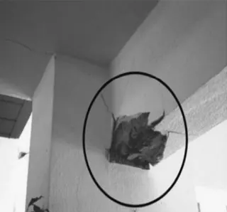
To identify the model of failure or damage of the beames in the given figure.
Observations:
- Concrete crushed & the reinforcement is exposed.
- Concrete spalled beyond the reinforcement which may be a sign of rupture.
- Beam top portion looks safe because of the flange advantage from slab.
- The crack develops from bottom to top means rebar yielding occurs in support bottom only.
Ans:
- Its form of fexural failure due to reversal of stress during earthquake.
- During stress reversal, support top experiences compression & bottom experiences tension.
- Top compression is managed by salb advantage. Bottom tension was not satisfied by the provided reinforcement.
- Since the reinforcement got yielded, it cannot be repaired
1b)
AIM:
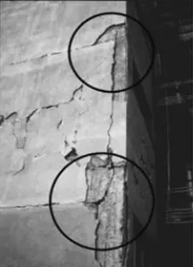
To identify the model of failure or damage of the beam-column edge in the given figure.
Observations:
- Cracks along Beam-Column edge.
- Cracks seem to have developed through the structure as it looks much wider.
- Beam looks separated from the column at joints.
- Concrete is not severely crushed.
Ans:
- Its beam pull out failure due to insufficient development lenght of reinforcement in joints.
- During earthquake, the horizontal movement of strucrure makes this condition worse & detached the beam member from column.
- Provideing anchorage lenght between two existing concrete is very difficult, So not repairable.
1c)
AIM:
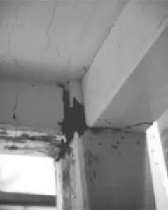
To identify the model of failure or damage of the column beam joint in the given figure.
Observations:
- Cracks are exactly at the joint of column Beam.
- Cracks in Beam developed through its entair width.
- Slab also developed more cracks along the beam width direction.
Ans:
- It's a plastic hinge failure.
- The damage occurredonly in the joint zone first of all.
- Cyclic lateral loading & stress reversal at the joints led to the damage.
- Even the slab participated to its best to handle the Tension ( slab is severely cracked means it has undergone tension with its flange condition), Butunable to control the damage.
- The joint can be strengthened.
2(a)
AIM:
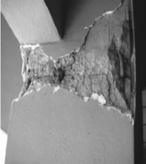
To identify the model of failure or damage at the top of the column in the given figure.
Observations:
- Concrete damaged at top of a column.
- Concrete damaged all around the column face.
- Beam are safe.
- The location of column looks at edge of the building.
- No wall are built along the column means it is probably at groung floor, for parking car movement access.
Ans:
- It's a safe sory failure, Technically plastic hinge formation.
- Due to absence of infill walls at the Ground floor, the plastic hinge forms at the top of ground story columns during lateral movement.
- Based on the development of crush of concrete, it can either be repairable or non-repairable.
2b)
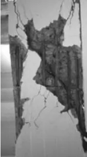
AIM:
To identify the model of failure or damage of the beams which is completely breakage in the given figure.
Observations:
- Concrete developed complete breakage diagonally.
- Longitudinal reinforcements are intact.
- Shear reinforcement spacing looks wider( which means probably lesser shear rebar provided).
Ans:
- It's a pure shear failure.
- Inadequate shear reinforcement compels concrete takes all the shear stresses.
2c)
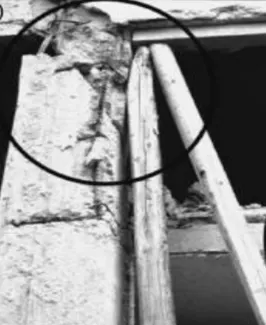
AIM:
To identify the model of failure or damage of the column in the given figure.
Observations:
- Column failed completely.
- Failure at top of column.
- There are two slabs connected to the column, probably one at mid height of the column.
- The wooden piles might be a post failure support after column failed, providing temporary prop to avoid collapse of the entire structure.
Ans:
- It's a short column failure.
- An additional slab or beam connected to a column in mid-height leads to this effect.
- This leads to failure especially if the connection is unintentional & not accounted in design.
- The failure given in the picture is not at all repairable.