Identification of Cracks
INTRODUCTION ON EARTHQUAKE AND DAMAGES AND FAILURES CAUSED :
Earthquake is the shaking of the ground caused by the sudden movement, breaking and shifting of section of Earth’s crust. It may also be defined as the vibration of the earth’s surface releasing energy in the earth’s crust. Earthquakes does not kill people directly instead many deaths and injuries are result from the collapse of buildings, bridges industrial shades and other structures. We cannot prevent natural disasters from striking but we can prevent their impact by making buildings more strong to resist their destructive forces. This can be achieved by
earthquake resistant structures.The fails are as follows:
THE SOIL FAILS
Earthquake moves the ground side to side and up and down simultaneously. The seismic forces are so powerful that they turned soft soil instantly into quick sand , destroying its ability to bear weight. Buildings constructed on either soft soil or on steeply sloped sites in a seismic zone quickly transform into land slide or mud slide therefore they are at higher risk .Taller buildings or those built of rigid concrete may stat intact but topple over in the unstable soil both problems can be directly attributed to the soil failure.
THE FOUNDATION FAILS
The most important that determines the foundation’s ability to withstand the forces of an earthquake is the buildings mass. When buildings are not design to resist multidirectional and intense side to side load during an earthquake particularly when earthquake hit in a series of waves. In that case foundation connection failure occurs and building literally slides off its foundation . It indicates that foundation was not strong enough to pull the structure above alongwith it.
A SOFT FLOOR FAILS
The floors with minimal interior sheer walls , additional floor to floor height or large open spaces with concentration of building mass above are known as soft floors . The concentration of earthquake forces is at ground floor where most floors are located these soft floors represents a break in a building’s structural continuity. Soft floors are less rigid than the building constructed on top of them .
A BUILDING JOINT FAILS
A building’s shape impacts its ability to resists deflection .In older masonry buildings the building expands that share a common wall with original structure if this connections do not accommodate the natural inclination of the different structure to move independently of each other or if there is insufficient clearance between the different structures , the results can be disasters in an earthquake. Two buildings located next to one another of different heights. In the event of an earthquake the strongest part of one building may be slammed repeatedly into the weakest part of the other.As a result one building can suffer a disastrous failure simply because of its close proximity to its neighbour building .
Question 1:
a)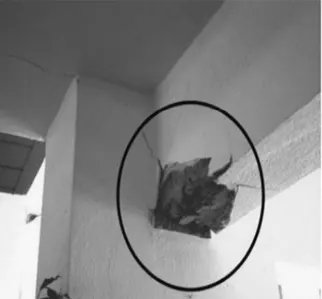 b)
b) 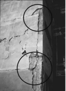 c)
c) 
What is the mode of failure or damage of the beams in the figure above? Are the damages repairable? Elaborate
AIM:
To analyse the mode of failure or damage of the beams in the pictures and if the damages repairable or not
INTRODUCTION:
1. Flexural Tension Failure
Flexural tension failure initiates by yielding of steel reinforcement followed by crushing of concrete at compression side of the beam. It occurs when the beam is under-reinforced; the reinforcement ratio in the beam is low than balanced reinforced ratio as per ACI 318-14.The signs of this type of failure are the development of cracks at the tension side of the beam which further extend to the compression side. These cracks are mostly vertical and located at the middle third of the beam. Great deflection is another sign of flexural tension failure.
2. Flexural Compression Failure
The flexural compression failure begins by crushing of concrete at compression side followed by yielding of steel at tension side of the beam. It occurs when the beam is over-reinforced which means the beam reinforcement ratio is greater than balanced reinforcement ratio as per ACI 318-14.This type of failure is sudden and does not provide warning i.e. brittle failure. That is why it is not desired from reinforced concrete design point of view.This type of failure can be prevented by avoiding over-reinforced concrete beam design or increasing compression strength of concrete by introducing steel reinforcement at the compression side or increasing the geometry of the beam.In summary, the flexural tension failure happens gradually i.e. ductile failure and it is desired failure type in beam design process.
PROCEDURE:
OBSERVATION:
As we can see that:
- Concrete crushed and the reinforcement is exposed
- Concrete spalled beyond the reinforcement which may be a sign of rupture
- Beam top portion looks safe because of the flange advantage from slab
- The crack developes from bottom to top means rebar yeilding occurs in support bottom only
RESULT:
- Its form of flexural failure due to reverse of stress during earthquake
- During stress reversal reversal, support top experiences compression and bottom experiences tension
- Top compression is managed by slab advantage. Bottom tension was not satisfied by the provided reinforcement
Since the reinforcement got yielded, it can not be repaired
Q1.b
INTRODUCTION:
The pull out failure of the longitudinal bars of the beam results in complete loss of flexural strength. This kind of failure is unacceptable at any stage. Hence, proper anchorage of the beam longitudinal reinforcement bars in the joint core is of utmost importance. The pull out failure of bars in exterior joints can be prevented by the provision of hooks or by some positive anchorage 9 . Hooks, are helpful in providing adequate anchorage when furnished with sufficient horizontal development length and a tail extension. Because of the likelihood of yield penetration into the joint core, the development length is to be considered effective from the critical section beyond the zone of yield penetration. Thus, the size of the member should accommodate the development length considering the possibility of yield penetration.When the reinforcement is subjected to compression, the tail end of hooks is not generally helpful to cater to the requirements of development length in compression10. However, the horizontal ties in the form of transverse reinforcement in the joint provide effective restraints against the hook when the beam bar is in compression
OBSERVATION:
- Cracks along Beam- Column edge
- Cracks seem to have developed thrugh the structure as it looks much wider
- Beam looks separated from the column at joints
- Concrete is not severely crushed
RESULT:
- Its a Beam pull out failure due to insufficient developmen length of reinforcement in joints
- During earthquake, the horizontal movement of structure makes this condition worse and detached the beam member from column
Providing anchorage length between two existing concrete is very difficult.So its not repairable
Q1.c
INTRODUCTION:
The seismic design philosophy relies on providing sufficient ductility to the structure by which the structure can dissipate seismic energy. The structural ductility essentially comes from the member ductility wherein the latter is achieved in the form of inelastic rotations. In reinforced concrete members, the inelastic rotations spread over definite regions called as plastic hinges. During inelastic deformations, the actual material properties are beyond elastic range and hence damages in these regions are obvious. The plastic hinges are “expected” locations where the structural damage can be allowed to occur due to inelastic actions involving large deformations. Hence, in seismic design, the damages in the form of plastic hinges are accepted to be formed in beams rather than in columns. Mechanism with beam yielding is characteristic of strong-column-weak beam behaviour in which the imposed inelastic rotational demands can be achieved reasonably well through proper detailing practice in beams. Therefore, in this mode of behavior, it is possible for the structure to attain the desired inelastic response and ductility. On the other hand, if plastic hinges are allowed to form in columns, the inelastic rotational demands imposed are very high that it is very difficult to be catered with any possible detailing. The mechanism with such a feature is called column yielding or storey mechanism. One of the basic requirements of design is that the columns above and below the joint should have sufficient flexural strength when the adjoining beams develop flexural overstrength at their plastic hinges. This column to beam flexural strength ratio is an important parameter to ensure that possible hinging occurs in beams rather than in columns.
OBSERVATION:
Cracks are exactly at the joint of column- Beam
Cracks in Beam developed through its entire width
Slab also developed more cracks along the beam width direction
RESULT:
Its a plastic hinge failure
The damage occured only in the joint zone first of all
Cyclic lateral loading and stress reversal at the joints led to damage
Even the slab participated to its best to handle the tension . Slab is severly cracked means it has undergone tension with its flange condition.But unable to control the damage
The joint can be strengthed therefore repairable.
Question 2:
a) 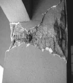
AIM:
To analyse the mode of failure or damage of the beams in the pictures and if the damages repairable or not
INTRODUCTION:
The soft story irregularity, refers to the existence of a building floor that presents a significantly lower stiffness than the others, hence it is also called: flexible story. It is commonly generate unconscientiously due to the elimination or reduction in number of rigid non-structural walls in one of the floors of a building, or for not considering on the structural design and analysis, the restriction to free deformation that enforces on the rest of the floors, the attachment of rigid elements to structural components that were not originally taken into consideration. Because of the effects produced by nonstructural components on the seismic performance of the building, the term non-intentionallynonstructural has been assigned to these components. If the soft story effect is not foreseen on the structural design, irreversible damage will generally be present on both the structural and nonstructural components of that floor. This may cause the local collapse,and in some cases even the total collapse of the building. The soft first story is the most common feature of soft story irregularity. It usually is present in modern frame buildings when a large number of nonstructural rigid components, such as masonry walls, are attached to the columns of the upper floors of a reinforced concrete frame structure while the first story is left empty of walls or with a reduced number of walls in comparison to the upper floors. The rigid nonstructural components limit the ability to deform of the columns, modifying the structural performance of the building to horizontal forces.
OBSERVATION:
- Concrete damaged at top of the column
- Concrete damaged all round the column face
- Beams are safe
- The location of column looks at edge of the building
- No walls are built along the column means it is probably at ground floor, for parking car movement access
RESULT:
Its a soft story failure, Technically plastic hinge formation
Due to absence of infill walls at the ground floor,The plastic hinge forms at the top of ground story column durin lateral movement
Based on the development of crush of concrete it can be either repairable or non repairable
b) 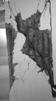
INTRODUCTION:
Shear failure occurs when the beam has shear resistance lower than flexural strength and the shear force exceeds the shear capacity of different materials of the beam. A shear load is a force that tends to produce a sliding failure on a material along a plane that is parallel to the direction of the force.
This type of failure is sudden and provides no warning i.e. brittle failure. The effective span to depth ratio of the beams and its size are important parameters in determining the type of shear failure.
Shear failure is an undesired type of failure and commonly stirrups are placed in the beam to prevent the shear failure. The shear failure mechanism is characterized by shear sliding along a crack in beam without shear reinforcement and yielding of stirrups in a beam with shear reinforcement. It is classified into the following forms:
1. Diagonal Tension Failure
Diagonal tension failure begins with the development of vertical crack (flexural cracks) at the bottom of the beam due to flexural tensile stress. Then, as the load on the beam increases, this crack growth both in width and length and bends in a diagonal direction as it moves to the upper part of the beam toward the loading point. After that, the last stage of shear tension failure occurs which is a sudden failure of concrete in shear.This mode of failure is common in beams with low or no web reinforcement. Diagonal tension failure occurs typically in beams with a shear-span to depth ratio (a/d) greater than 2, but could occur also for lower values of a/d
2. Shear Compression Failure
Shear compression failure begins by initiation and development of cracks in the beam cross-section. Then, these cracks propagate and penetrate the compression zone of the beam, and the final stage of the failure occurs when the compressive strength of the concrete is exceeded.The crushing of concrete takes place at the tip of the diagonal crack in the area around the point of load application. Fig. 4 illustrates the development of cracks at the location of shear compression failure in a beam.Shear compression failure is mainly related to high amount of shear reinforcement. Finally, shear compression failure can occur in beams with span to depth ratio of less than four.
3. Splitting Shear (True Shear) Failure
When the shear span to depth ratio of a beam is less than one, splitting shear failure can be expected. Commonly, this type of beam is called deep beam in which loads are directly transferred to supports, and shear strength is much higher than in ordinary flexural beams.Sometimes, failure in compression of the region adjacent the supports may occur instead of splitting shear failure.
OBSERVATION:
- Concrete developed complete breakage diagnolly
- Longitudnal reinforcements are intact
- Shear reinforcement spacing looks wider which means probably lesser shear rebar provided
RESULT:
Its a pure shear failure
Inadequate shear reiforcement compels concrete takes all the shear stresses
c) 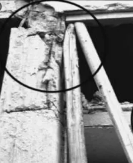
INTRODUCTION
A building constructed on a sloped ground under earthquake action is forced to move along with the floor. If both long and short columns are present, a majority of the force is attracted by the short columns and suffer more damage compared to long columns. Short column effect is also observed in the columns that support loft slabs or mezzanine floors. These elements are added between two existing floors. Another case is the presence of short and long column on the same floor level. Here too the short column offers more resistance compared to long columns. Thus short columns are subjected to more force and damage.The short columns are stiffer compared to long columns and hence most of the earthquake forces acting on the building are taken by the short columns. More the stiffness of any structural element, less will be its flexibility to undergo any sort of deformation. Earthquake design of a building is more efficient through the flexible design of the structure.
OBSERVATIONS:
Column failed completely
Failure at top of column
There are two slabs connected to columns , probably one at mid of the column
The wooden piles might be a post failure support after column failed, providing temporary prop to avoid collapse of the entire structure
RESULT:
Its a short column failure
An additional slab or a beam connected to a column in mid height leads to its effects
This leads to failure especially if the connection is unintentional and not accounted in designs
The failure shown in the picture is not at all repairable
- Samim AkhtharHii Plz call me 7323821663 Still what are you doing?