Hood design-Week 2
Design and Development of Car engine HOOD
The objectives of this project are
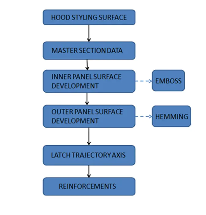
- To design Hood Outer and Inner panel along with suitable reinforcements by following the Master Section.
- Hood Styling Surface is used as Input and with suitable reinforcement structures
- Determine the Latch Trajectory Axis and Hinge Axis followed by assembly of the parts
DESIGN METHODOLOGY
DESIGN REQUIREMNTS
The Basic Design requirements for Hood design are
The Basic Design requirements for Hood design are
- Opening Angle Situation
- Emboss of Inner Panel
- Hemming and Relief along the outer panel
- Hinge Axis Definition and Latch and Striker Position
- Stiffener Pad and Mastic Sealant for NVH Improvement
- Positive Draft Angle for Deep drawn steel parts
HOOD
hood is the hinged cover over the engine of motor vehicles. Hoods can open to allow access to the engine compartment
Components of Hood
Hood components are:
- Outer Panel
- Inner Panel
- Hinge
- Latch
- Reinforcement
OUTER PANEL
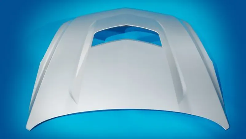
A car hood panel is one of the most important components of the BIW (body in white), it is considered as the closure sheet-metal component. The outer panel has the aesthetic look to it but on its own is very weak and not capable of handling force during impact. Most automobile hood outer panels are made of traditional steel plates, and their quality does not meet the needs of lightweight development. For this reason, it is necessary to obtain lightweight effects through the application of the automotive aluminium sheets. The most widely used car aluminium alloys in the market are deformed aluminium alloys of 6111, 6016, and 5182. The production process of the outer panel of the hood mainly includes blanking, deep drawing, trimming, turnup, and side turnup. Among them, deep drawing is a key process to ensure the quality of parts.
INNER PANEL
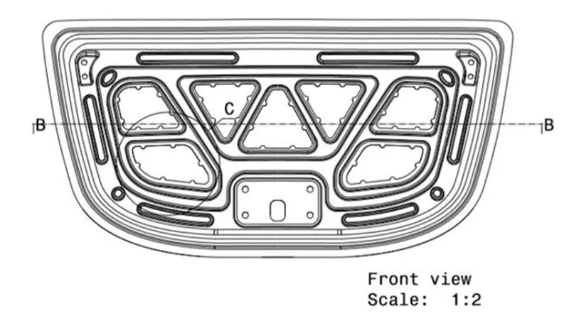
The inner panel of the hood is not visible to the customer, but this is the engineering feature of the outer panel. The hood panel is required to have a high initial reaction force against the impact exerted on the hood in order to enhance the energy absorption capacity. The hood is further required to minimize a reduction of a reaction force by deformation in collision. A hood inner panel according includes an inner panel main body forming part of a hood of a vehicle, a front bead provided on the inner panel main body and extending along a vehicle width direction, and a rear bead provided on the inner panel main body, located on a rear side of the front bead and extending along the vehicle width direction. The front bead includes a center portion in the vehicle width direction that is curved toward a front of the vehicle and located in front of each end portion in the vehicle width direction, and the rear bead includes a center portion in the vehicle width direction that is curved toward a back of the vehicle and located behind each end portion in the vehicle width direction.
HINGE
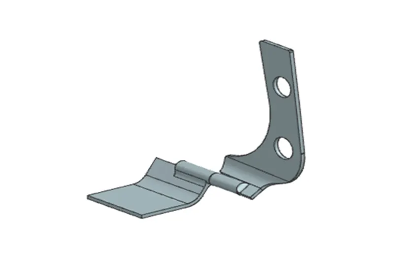
hinge is a machine element that connects two bodies allowing angular movement about a fixed axis of rotation, all the while preventing translations and rotations on the remaining two axes. A hinge can be considered as a journal bearing with only one degree of freedom where a shaft is rotating in a hole. Hinges only allow one rotation, either yawing (the most common), pitching, or rolling. Hinges are a jointed and flexible device that is attached to any swinging part. Hinges are mechanical bearings that are used to connect two swinging objects or points to one another and give them the freedom to move relative to each other. Hinges have limited movement, allowing the joint to move only at one angle and restrict the other movements of swinging parts.
LATCHE
Latches are mechanical components that allow the temporary joining of parts that are moving relative to each other. They are actuated to release the coupling and allow the two parts to separate. Latches are mostly seen on doors and enclosure openings. They are also used in devices such as seat belts, clamps, straps, and objects with retractable parts. Different designs feature various methods of actuation, holding style, and mounting. The hood latch is an extremely simple latch. When the hood is closed, the latch slides over what is called a catch, and a spring covers the latch to keep it snug. When we pull the knob inside the car to open the hood, the hood latch cable opens the latch, allowing it to bypass the catch and open.
REINFORMENT
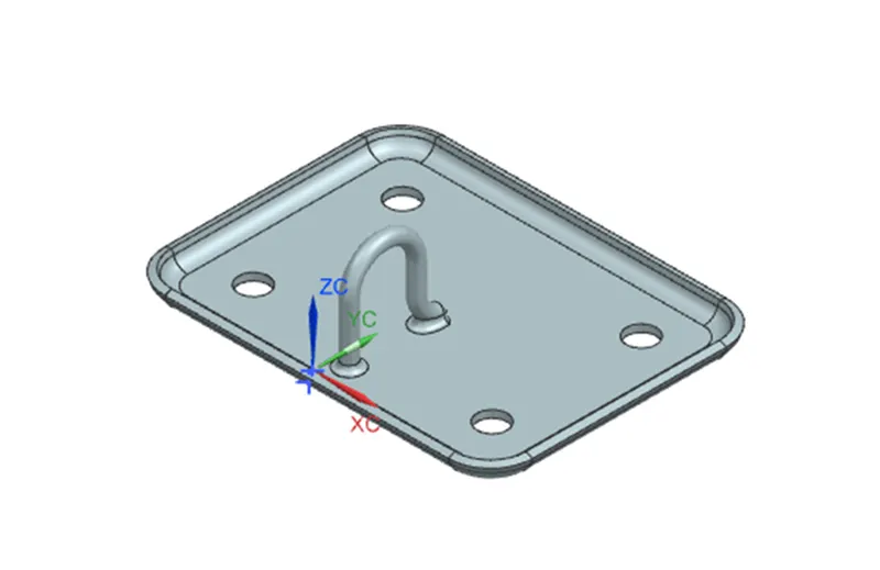
reinforcement – Reinforcement is defined as to strengthen something that is weak or to add some strength by adding more material to the weak spot. Reinforcement is automobile is done to strengthen the surfaces so that they can bear the load if collision occurs. The reinforcement surfaces are also provided to attach the hinge and latch to the hood inner panel. Reinforcement is done at the embosses of the hinge and the latch. A 1.5mm of sheet metal is provided at these parts as direct forces act on these.
LATCH TRAJECTORY
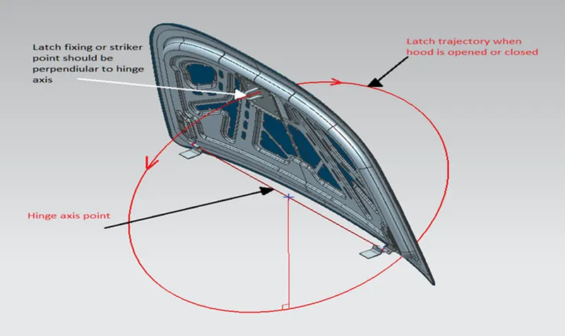
The latch trajectory helps us to fix the striker at the proper place in the hood. Taking centre of axis of hinge, a circle is drawn taking the striker distance as the radius. It is positioned tangent, so that perpendicularity is obtained. The circle is the direction of the opening or closing of the hood. To ensure proper opening and closing of the hood latch trajectory is required, so that the striker is in its correct position.
MASTIC DATA
he hood inner and outer panel are joined together by hemming but then also we use mastic sealant to properly seal all the area of the hood. This seal is done to reduce the NVH (noise, vibration, and hinderance) and to provide waterproof seal. A sealant in liquid form is applied to the inner panel at the proper areas so that it seals the complete hood. The Mastic sealant or the Mastic point is an elastic compound that behaves like a rubber. The mastic points are defined on the hood inner panel where the hood can easily deform. They help the hood outer panel to come back to its original shape after it gets deformed. The mastic has an influence area of 80mm. The sealants areas are drawn while the designing of the inner panel and while designing these points the thing to be considered is that they cover all the area of the hood so that no area is left otherwise while in moving condition it will produce some NVH.
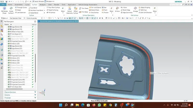
EMBASS
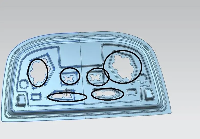
Sheet metal embossing is a stamping process for producing raised or sunken designs or relief in sheet metal. This process can be made by means of matched male and female roller dies, or by passing sheet or a strip of metal between rolls of the desired pattern. It is often combined with foil stamping to create a shiny, 3D effect. The metal sheet embossing operation is commonly accomplished with a combination of heat and pressure on the sheet metal, depending on what type of embossing is required.
Metal sheet is drawn through the male and female roller dies, producing a pattern or design on the metal sheet. Depending on the roller dies used, different patterns can be produced on the metal sheet. The pressure and a combination of heat actually "irons" while raising the level of the image higher than the substrate to make it smooth. The term "impressing" refers to an image lowered into the surface of a material, in distinction to an image raised out of the surface of a material.
HEMMING
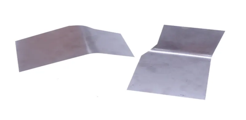
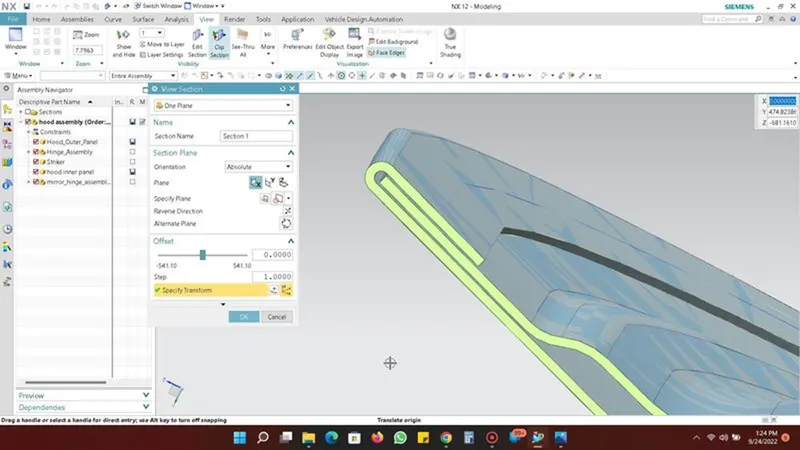
Hemming is a metal working process in which a sheet metal is folded over onto itself. Normally hemming operations are used to connect parts together, to improve the appearance of a part and to reinforce part edges. Hemming between the inner and outer panel, it is used joining the inner and outer panel and used instead of spot welding as surfaces cannot be joined with welding process. Hem flanges are protected by a sealant to prevent crevice corrosion of the sandwiched metal. In principle, the hemming technique produces sufficiently strong mechanical joints around the periphery of closure panels When force is applied during hemming process there may be a change of shape which is examined, and relaxation is given in those areas to decrease the stress concentration.
- Deep Drawing
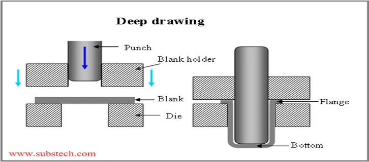
Deep drawing is a sheet metal forming process in which a sheet metal blank is radially drawn into a forming die by the mechanical action of a punch. It is thus a shape transformation process with material retention. The process is considered "deep" drawing when the depth of the drawn part exceeds its diameter. This is achieved by redrawing the part through a series of dies. The flange region (sheet metal in the die shoulder area) experiences a radial drawing stress and a tangential compressive stress due to the material retention property. These compressive stresses (hoop stresses) result in flange wrinkles (wrinkles of the first order). Wrinkles can be prevented by using a blank holder, the function of which is to facilitate controlled material flow into the die radius.
Design consideration
Car bonnet is the important component which is utilized for several purposes at the front. It gives access to the engine compartment which enable the repair and maintenance of many parts namely car engine, radiator etc. Therefore, bonnet must be designed in suitable manner, and it should minimize the hindrances from the disturbance caused by the external environment on the hood and its components below it. When the car is in running condition, the resisting forces from the air acting on the hood. Therefore, the design of the bonnet should be made aerodynamic to reduce the air resistance.
- Head Impact Zone – According to recent surveys lots of pedestrian losses their lives and are severely get their head damaged during the accident. The pedestrian are adults, children, cyclist, or others. So, to keep these things in mind the hood design is done in such a way that it injured the pedestrian as less as possible.
So, the hoods are designed in two ways –
- Wrap around hood

2.Inlaid hood

According to different regions, head zones are defined by considering the average heights of pedestrians. The below image shows American, European, and Japanese head zone standards. The opening angle of the hood is also decided as per predefined standards.
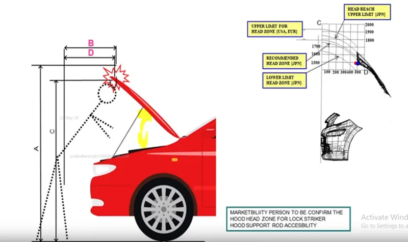
Wrap around distance is the trace of points received on the front structure when one end of the flexible tape of required length is held at the ground reference line and the other end in contact with the front structure.
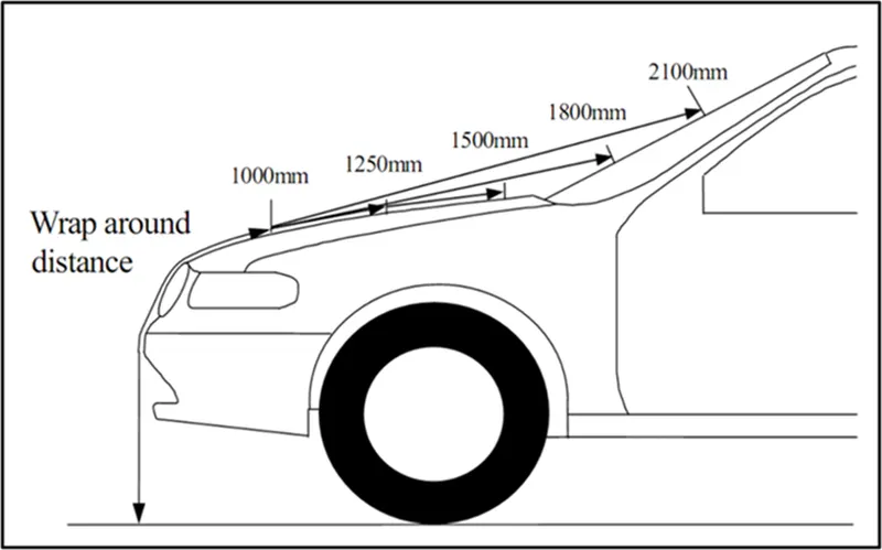
When a child hits on a hood his head will fall between 1000 to 1500 mm area whereas. When an adult hits on a hood his head will fall between 1500 to 2100 mm.
EURO NCAP Test
EURO NCAP Test is performed to check the safety of pedestrians by considering head impact, leg impact, etc.
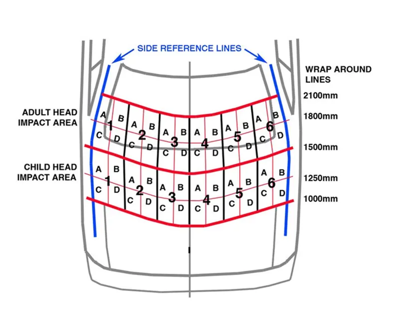
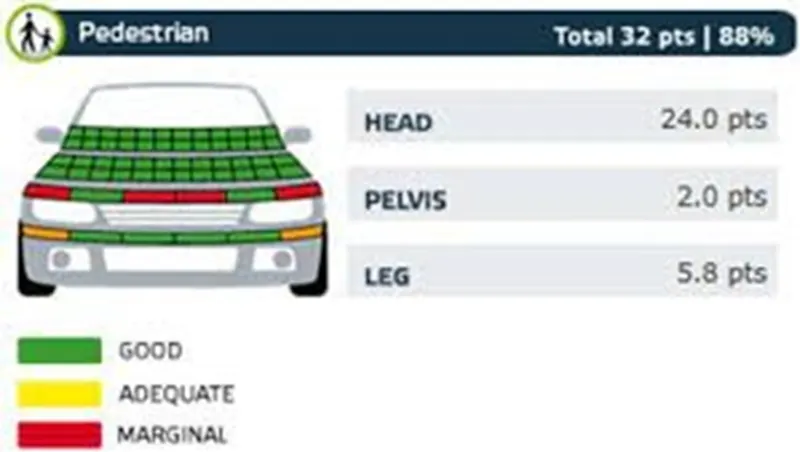
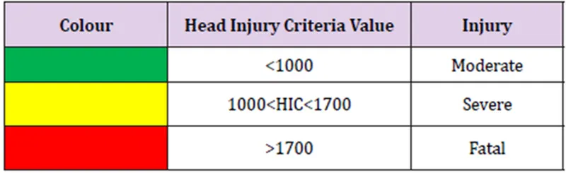
As per NCAP Head impact criteria should be below 1000 to have a moderate injury. The hood designer's aim is to develop a hood having a major green zone.
Where t1 and t2 are the initial and final times (expressed in seconds) of the interval during which the HIC attains a maximum value and a(t) is the resultant acceleration (expressed in G) measured at the head CG.
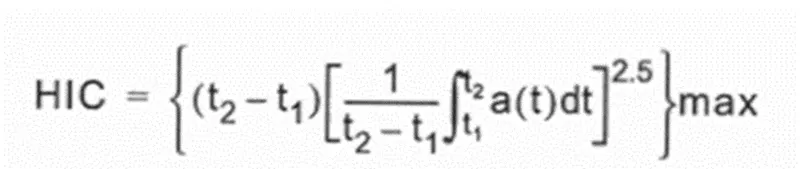
The time duration (t1-t2) used in the calculation should be taken as the contact time for the impact, however, this is often very difficult to ascertain in physical evaluations using crash test dummies or head form simulators. In using HIC for assessing the potential of concussion than a maximum time duration of 15 msec should be used, which was the maximum time duration for which the original tolerance curve was developed. Longer contact time durations can be used to predict skull fracture.
The highest acceleration, independent of location or direction, should be used in the Head Injury Criterion, which will therefore be the resultant acceleration measured at the head's centre of gravity.
After a test, points are allocated to the impact portion (which shows the color code at impact areas), and accordingly, a pedestrian safety rating is assigned to the vehicle. The below Image shows different color zones for pedestrian safety.
Head Impact Injury Criteria
- Gas Stay or Support Rod – The gas stay, or support rod help to keep the hood open. While designing hood the position of support rod should be considered in both open and close position. While in close position the support rod should rest in such a way it doesn’t touch any other component, and if touches with any part, then vibration will be produced, and it will also create noise. And, in the open position it should be such that it can easily withstand the load of the hood.
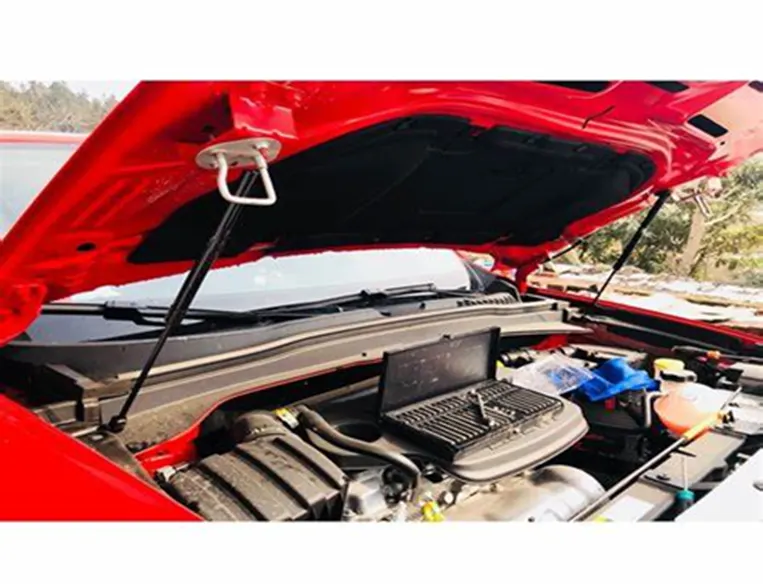
- Opening of Hood – When the hood open there should be a space of 15 to 30 mm so that the fingers can place in that space to lift the hood.
- Other parameters –
- Outer panel = .75mm
- Inner panel = .75mm
- Reinforcement = 1.5mm
- Thickness of hood
- Relief in rear and front section of the inner and outer panel for hemming.
- Gap between inner and outer panel for hemming.
- inner Pannel Design :
Take a file from download section which is outer pannel and process on it for the design of inner pannel, the dimensions and the drawing of inner pannel are shown in the question and referance video.
The drawing for design of inner pannel are as follows :
Master Section:
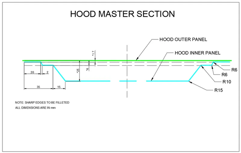
by follow the above drawing we have to produce inner pannel
- Command used for inner pannel design :
- Offset Surface
- Offset Curve on Surface
- Trim Sheet
- Through Curves
- Law Extension
- Emboss
- Edge Blend
- Face Blend
- Datum
- Sketch
- Sew
- Thicken
- Curve on Surface
- Mirror Geometry etc......
By using above command we have to design the inner pannel,
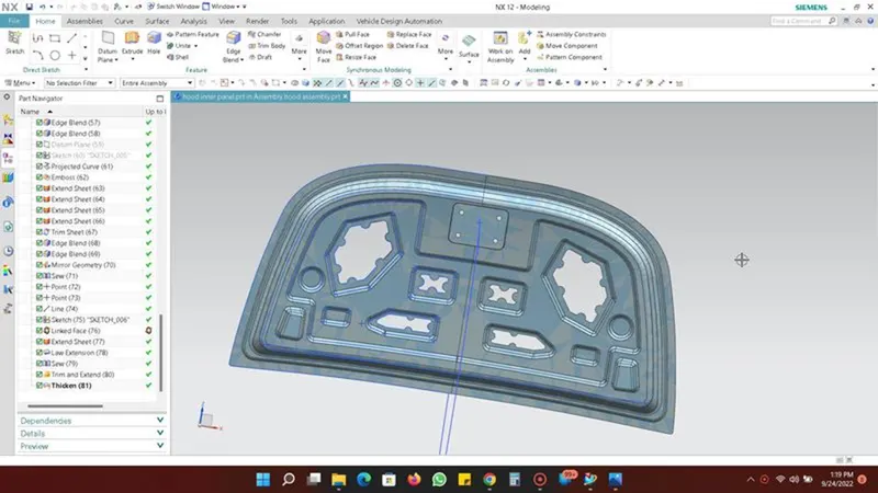
- Outer Pannel Design :
Requirements :
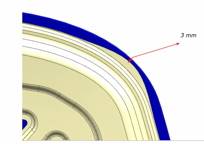
Hemming Data:
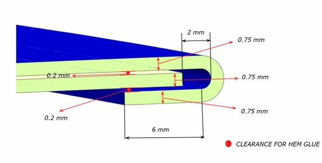
Relief rear section:
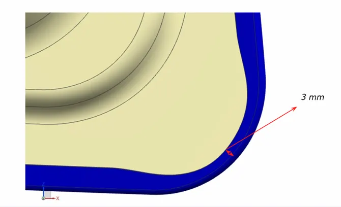
Front relief:
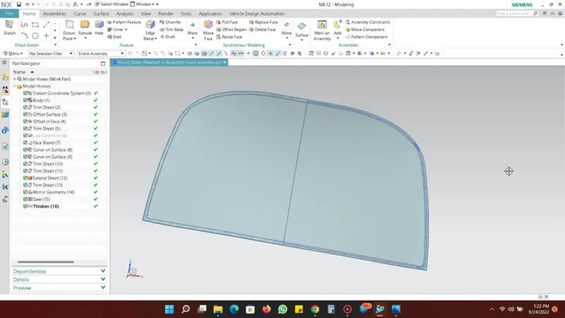
By using above information we have to modify the outer pannel of HOOD
- Hinge Assembly Placement :
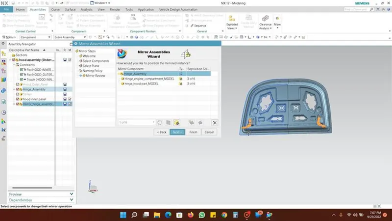
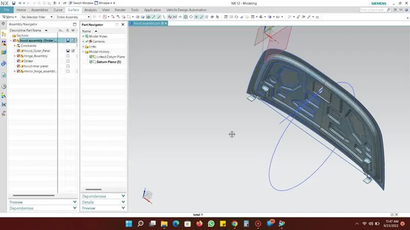
For the placement of hinge assembly we have to create emboss on the inner pannel for rest the hinge for that we generate the Datum plane and draw sketch for emboss.
After doing the emboss the command Move Component and Assembly Constraints are used to proper fix and rest the hinge on that emboss on inner pannel.
- Stricker Placement :
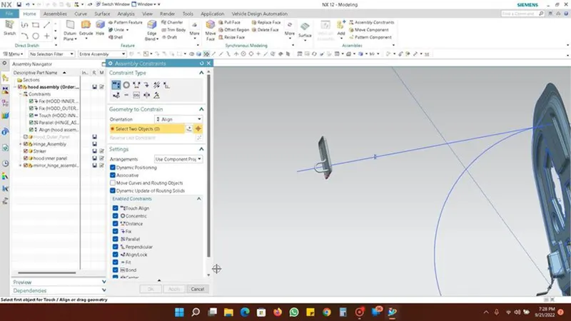
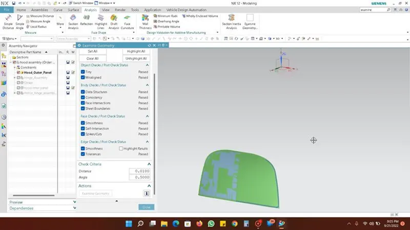
For the placement of stricker we have to sketch the circle which is perpandicular to the inner pannel, then draw the horizontal and vertical line in centre point, give some angle to the lines for proper placement of the stricker.
Using the Touch Allign and Parallel Allign for the proper placement.
https://drive.google.com/file/d/16bvg5_SDnr8QYSRHCkP90jaNZygGJZnX/view?usp=sharing
Conclusion :
We have designed a hood that falls under the rules & regulations of the manufacturer's standards.
- The design parameters of the inner panel including master sections are followed.
- The inner panel and outer panel designed with a thickness of 0.75mm.
- The outer panel is developed with a hemming flange.
- The reinforcements parts of the required places are created.
- The hood is assembled with hinges and a striker.