Hood design-Week 2
HOOD DESIGN
Introduction
Hood or Bonnet of the car is a hinged cover over the engine. During repair and maintenance it allows accessing to the engine compartment to inspect engine room, replenishing cooling water and engine oil, changing parts etc. It also protects the parts under hood from direct sunlight and dust.
An assembly of hood consists of hood outer panel, hood inner panel, latch and striker, hinge, hood stay. Hood is typically made out of the same material as the rest of the bodywork. This may include steel and aluminium.
Design parameters
Outer Panel Thickness = 0.75mm
Inner Panel Thickness = 0.75mm
Reinforcement Thickness = 1.5mm
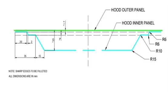
Figure 1: Hood master section
COMPONENTS
- Hood outer panel
Hood outer panels are a metal cover which is responsible for aesthetic elements of a car. The styling team provides the skin for the outer panel. The outer panel is attached to the inner panel by hemming process. So, it is necessary to provide the required hemming flange and reliefs for the hemming operation.
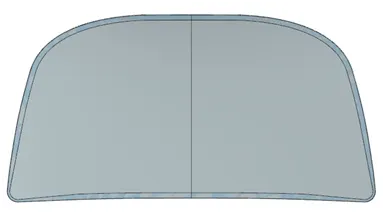
Figure 2: Hood outer panel
- Hood inner panel
Hood Inner panel gives strength and rigidity to the hood outer panel. The master section represents the initial emboss shape and size. Then we provide emboss for the latch and hinge elements after fixing the location.
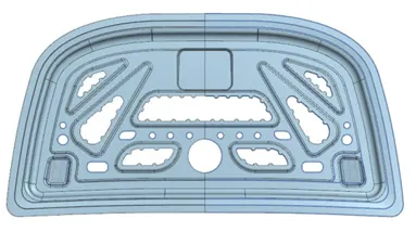
Figure 3: Hood inner panel
- Hinges
It is a pivoting point from which the hood opens and closes. One part of the hinge is fixed with the engine compartment, while other part is connected to hood.
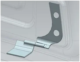
Figure 4: Right hinge
- Latch and Striker
Latch and striker mechanism is provided to lock the hood, in order to prevent accidental opening of the hood during driving. The latch is present on the engine compartment while the striker is attached to inner part of hood.
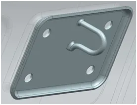
Figure 5: Car Hood latch striker
- Reinforcement
The reinforcements are provided to the hood inner panel to provide extra strength to compensate for the loss of strength near component installation (mainly at the hinge and latch) regions. Usually thickness of reinforcements will be higher than that of the inner panels and the value varies according to cost and requirement.
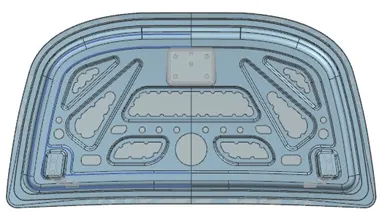
Figure 6: Hinge and latch reinforcement
- Hood stays - A device that supports the hood in open position. It is also called as hood balancer rod.
- Support Rod – they are manually operated and they are cost effective and simple to design
- Gas Stay - They require no man power but they are costly.
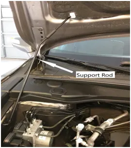
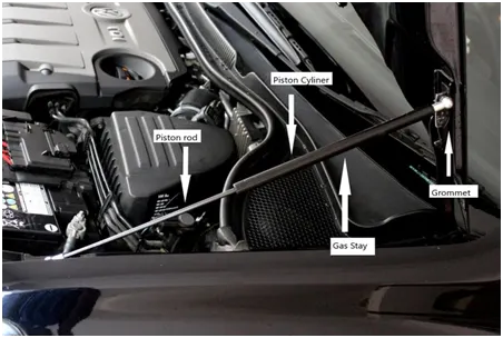
Figure 7: Support rod and Gas stay
Latch Trajectory
Latch trajectory is given by the circle drawn from the hinge axis point. Hinge axis point is the centre point of the hinge axis. First, we can fix either the latch or the hinge. If we have fixed the hinge position then we should plot the Trajectory circle for the latch. For proper mating condition the striker axis through the tip of the striker should be tangential to the latch trajectory.
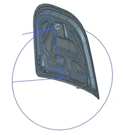
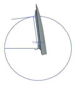
Figure 8: Latch trajectory
POSITION OF STRIKER AND HINGE
For the proper opening and closing of the hood, the striker should be perpendicular to the trajectory of the hood. For this, hinge is assembled at its position. Once it is placed, hinge axis is drawn.
To check the hinge axis as the center we draw a big circle to the position the latch in such a way that it is perpendicular to the hood trajectory.
In between the two hinges, the striker is perpendicular to the midpoint of two hinges, because while closing and opening of latch and striker the opening position will have similar actions.
Mastic Sealant
We cannot use any other joining techniques like welding, riveting etc on hood outer panel because they will leave marks behind on the hood outer panel which will spoils its aesthetic appearance. So, mastic sealants are used to stick the inner surfaces of outer panel and inner panel.
Mastic sealants are elastic compound. It is applied between the inner and outer panels at specified spots. Each spot of mastic sealants has its effect around a circular region of 80mm diameter. Mastic sealant covers the areas away from the hemming & which are more vulnerable to vibrate.
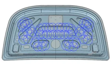
Figure 9: Mastic regions
MANUFACTURING PROCESSES
Deep Drawing
Deep drawing is a sheet metal forming process in which a sheet metal blank is radially drawn into a forming die by the mechanical action (combination of tensile and compressive) of a punch. The process is considered as "deep" drawing when the depth of the drawn part exceeds its diameter. This is achieved by redrawing the part through a series of dies. The flange region (sheet metal in the die shoulder area) experiences a radial drawing stress and a tangential compressive stress due to the material retention property. These compressive stresses (hoop stresses) result in flange wrinkles. Wrinkles can be prevented by using a blank holder, the function of which is to facilitate controlled material flow into the die radius.
Embossing
Embossing is a stamping process for producing raised or sunken designs in sheet metal. Throughout the hood inner panel we designed different embosses. It increases the stiffness of the hood inner panel through these embosses. The shape and size of embosses also determines the direction of the force distribution resulted from frontal collision. The force should be always distributed away from the passengers.
Characteristics of the metal embossing process include-
- Used in medium to high production runs for ductile metals
- Ability to maintain the same metal thickness before and after embossing
- Ability to produce unlimited patterns, depending on the roll dies
- Ability to reproduce product with no variation.
Hemming
Hemming is a forming operation in which the edges of the sheet are folded or folded over another part in order to achieve a tight fit. Hemming operations are used to connect parts together, to improve the appearance of a part and to reinforce part edges. In car production, hemming is used in the assembly of hoods, doors, trunk lids and fenders. The accuracy of the hemming operation is very important since it affects the appearance of the surface and surface quality.
Material deformations, which occur during the hemming process, can lead to dimensional variations and other defects in parts. Typical hemming defects are splits or wrinkles in the flange, material overlaps in the corner areas or material roll-in. That is why it is important to provide required reliefs at the corners.
There are two types of hemming operations-
- Conventional die hemming
- Table-top hemming
- Roll hemming- Roll hemming is carried out incrementally with a hemming roller. An industrial robot guides the hemming roller and forms the flange. It is the roll hemming process that is used for automotive sheet metals. Roll hemming is very flexible to use and tool costs are significantly lower as compared to those of conventional die hemming.
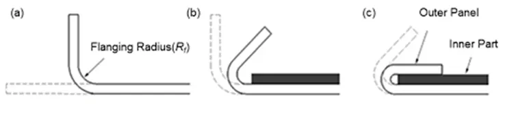
Figure 10: Hemming process in automotive sheet metals
Piercing & Blanking
It is a shearing process in which the sheet metal is pierced with a machining tool, resulting in the creation in a particular shape hole in the sheet. The major difference between blanking and piercing is that in blanking the cut out is the work piece and outer part is scrap, while in piercing, the cut out is scrap and the outer sheet is the work piece.
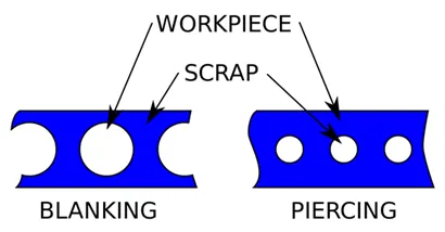
Figure 11: Piercing and Blanking
Design Standards
- Head clearance zone
- Noise Vibration Harshness (NVH) / Noise and Vibration (N&V): The study and modification of the noise and vibration characteristics of vehicles. While noise and vibration can be readily measured, harshness is a subjective quality, and is measured either via "jury" evaluations, or with analytical tools that can provide results reflecting human subjective impressions.
- Force distribution when subjected to frontal collision. The inner panel are strengthen by creating embosses and the design of embosses should be such that the force due to impact should be directed outside the car rather than inside the engine compartments.
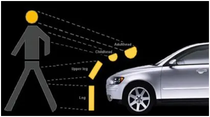
- The most important criteria in designing a bonnet are pedestrian safety from a frontal collision. The EURO NCAP has developed series of crash test and rating systems for assessing pedestrian, driver, and passenger injuries during impact with of the vehicle.
Wrap around distance: It is the distance from the road to the point where the head of the pedestrian collides with the hood.
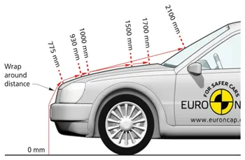
Side reference line: A line is drawn at 45 degree from the ground such that it touches the end of the hood. This type of hood is called the inlaid hood. If the end of the point of the side reference line is at A-pillar then it is called the wrap-around hood.
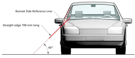
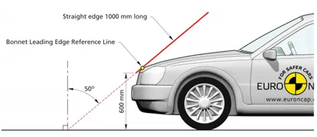
The position of the side reference line is important because if the side reference line is on the hood resulting in a bigger hood the wrap-around distance will be less and hence the impact zone will be more. But if the side reference line falls on the fender which makes the size of the fender bigger resulting in a lesser hood size which in turn results in high wrap around distance and lowering the impact zone.
Also when the material is removed from the hood, it gets softer in that region which results in lesser force impact force during the collision. This is done to increase the rating in the crash safety test. It is to make sure that there is no reinforcement given at the wrap-around distance in order to reduce damage to head injuries to pedestrians in case of head-on collisions.
Final Assembly
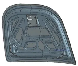
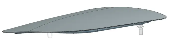
Figure 12: Assembly of hood
CONCLUSION
This hood was designed in Siemens NX Student Version software with given and required design guidelines for hood design and manufacturing.