Hood design
HOOD DESIGN USING NX CAD
INTRODUCTION
The Hood is an opening body panvel that covers the engine in a front engine vehicle. The hood is also considered as another type of door in a vehicle as it consists of an outer panel and an inner panel. The inner panel povides strength while the outer panel functions as the metal cover.
OBJECTIVE
The objective of this project to get familiar with the tools of nx cad and also to learn and understand the basic engineering principles for designing the inner panel of a hood.
METHODOLOGY
The styling team will give us the skin data. The design engineer will study the engineering feasibility of that part with also taking into consideration the NCAP standards and will give feedback so that they can change the styling of the hood accordingly.
Master section is provided for different regions.
Also many predefined values are given to us according to which we have to engineer and design the sketch and model the hood.
After that the CAE engineer will do analysis and testing on the part modelled and then will the report or feedback to the hood engineer and will do the necessary changes.
DESCRIPTION
To design a hood inner panel we should comsider-
-
NVH
-
Gas stay mounting
-
Latch and striker point
-
Hinge axis
-
Deformable bracket
-
Pedestrian ratings
-
NCAP rating
For every region we have a master sketch. Master sketch is a predefined sketch which is adaptable in diffrent sitiations. Here also we have a master sketch with the help of which we have designed the inner oanel of the hood.
When producing or manufacturing the inner panel of the hood the parts are deep drawn.
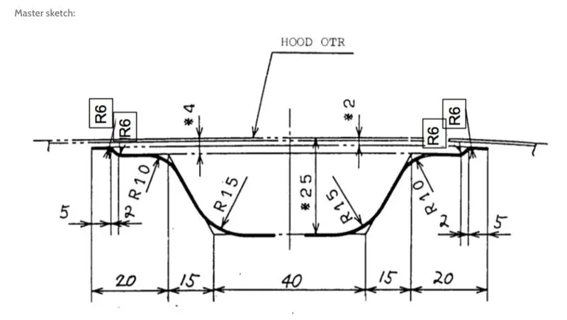
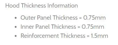
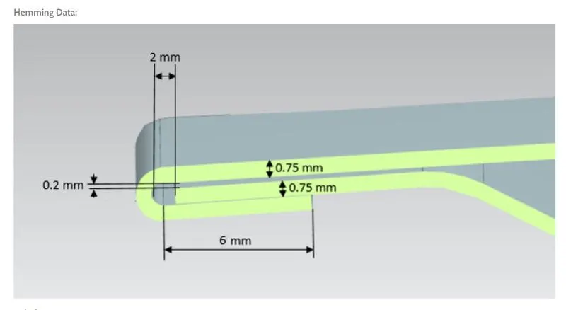
There were also many predefined values and data given to us for designing the hood, those are-
Relief data:
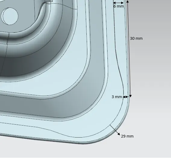
Front relief:
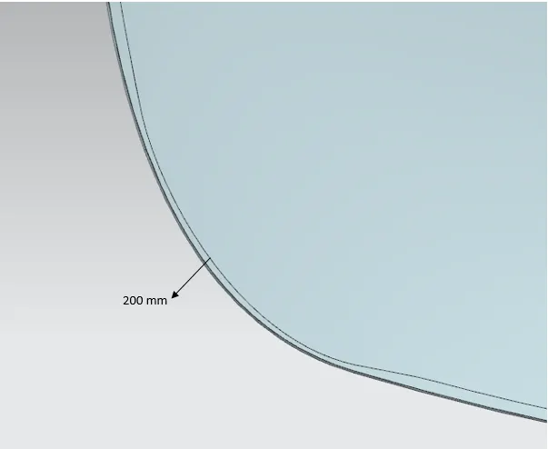
Deep drawing-
Deep drawing is a sheet metal forming process in which a sheet metal blank is radially drawn into a forming die by the mechanical action of a punch. It is thus a shape transformation process with material retention. The process is considered "deep" drawing when the depth of the drawn part exceeds its diameter.
We give a positive draft or an angle for better drawing process.
Process definition:
The deep drawing process is a forming process which occurs under a combination of tensile and compressive conditions. A flat sheet metal blank is formed into a hollow body open on one side or a hollow body is formed into a hollow body with a smaller cross-section. [DIN 8584]
Deep drawing processes are divided into three types:
-
Deep drawing with tools
-
Deep drawing with active means
-
Deep drawing with active energy
In the automotive industry, deep drawing is usually carried out using rigid tools.
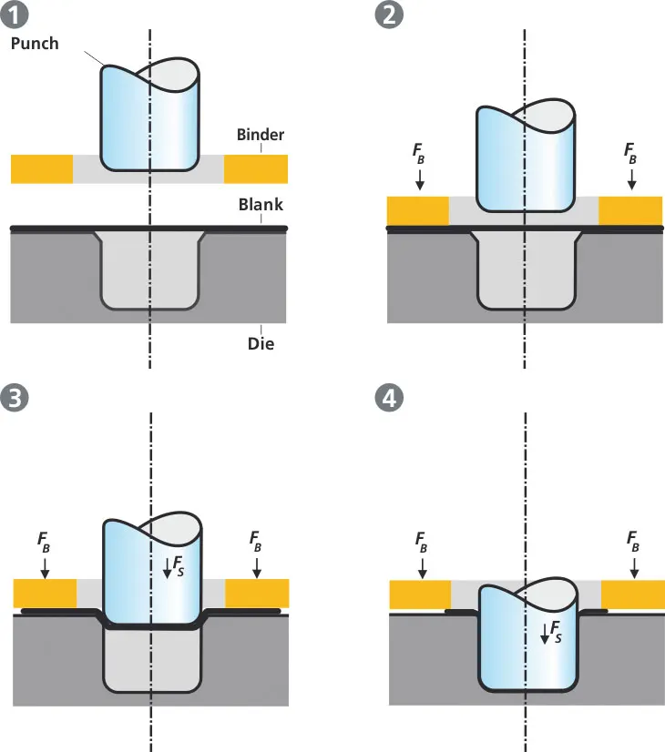
The figure illustrates the deep drawing process. The rigid tools consist of a punch, die and binder. In deep drawing, the plate holder closes after the metal sheet blank has been inserted.
Next the sheet is clamped between the die and the binder. This process slows down the flow of the sheet while it is being drawn and thereby prevents wrinkles from forming under the binder. The punch stretches the sheet over the die radius and forms it in the die. The amount of punch force necessary for forming is thereby continually increased up to the lower dead center of the punch.
Whereas in pure deep drawing there is no reduction of sheet metal thickness, forming is achieved in stretch forming purely as a result of a decrease in sheet metal thickness. Stretch forming is extensively used for the forming of only slightly curved parts with low depth of draw (e.g. roofs, doors).
When drawing complex car body parts in practice, there is usually a combination of stretch and deep drawing involved. It is necessary that the sheet metal is stretched as well as possible without reaching the material’s limits (e.g. splits, wrinkles).
There are approximately 300 to 400 sheet metal parts which fit together to form the body of a car. In order to manufacture high quality sheet metal parts optimally for their particular use, specialized software simulates the complete deep drawing process.
After we create a basic sheet model we then try giving some emboss using some basic engineering principles.
Emboss-
A carve, mould, or stamp a design on a surface or sheet metal so that it stands out.
We create embosses on the panel for providing stiffness to the panel.
Also we have to design the emboss in such a way that the forces dissipates the energy outside and arrest the motion of the energy going in straight direction.
So during an accident when the hood experiences the force the embosses will try to dissipate the energy outside so that it does not enter the cabin and harm the passenger.
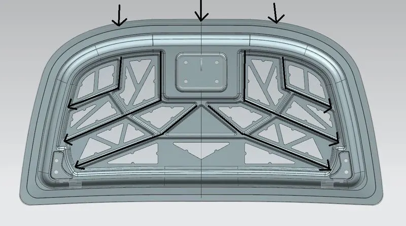
So after creating the emboss we have to position the hinge, latch and striker in the hood.
Latch and striker positioning-
For positioning the latch and striker first we will position the hinge onto the hood tentatively.
Then we will draw a straight line between the two moving axis of the hinge. The line will act as an axis along which the hinge will move or we can the hood open or close.
From the centre of the axis we draw a circle with the centre of the axis as the centre on the xy plane.
The circle will infer two things. First the trajectory of the hood opening and closing and second the position of the striker.
The striker should be exactly perpendicular to the trajectory then the hinge position is correct. If not we should change the position.
Then we will create some local emboss for the hinge and striker.
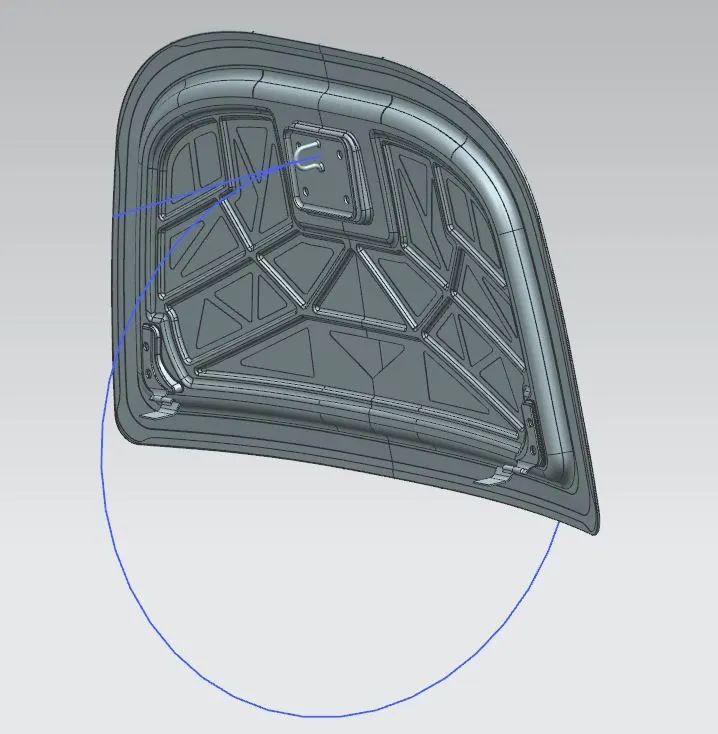
When we give this emboss and place the hinge and striker we lose some strenght and when we lose some strenght there is need to give additional reinforcement to compensate that.
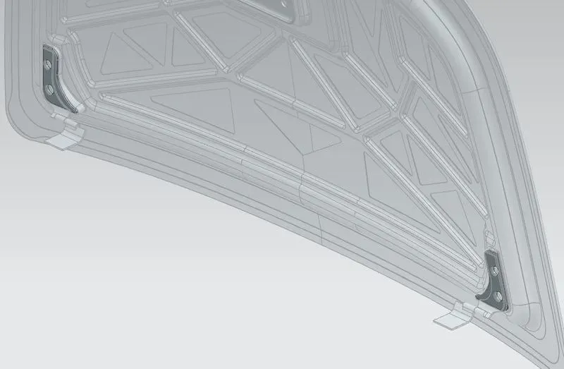
To imrove the strenght locally we also add stiffner pad between the hood inner oanel and hood outer panel to avoid vibration.
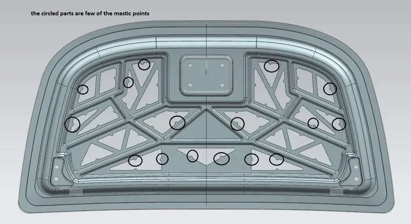
We also add mastic points.
Mastic sealant-
Every mastic sealant which we have provided in the region have the tendency to increase the strenght locally at around 80mm diameter.
We position the mastic sealant in such a way that most of the hood regions are covered.
This also helps improve the NVH.
It is like the hard rubber and it is first pasted on the points and when the panel goes through the furnance the paste gets hardened.
Mastic also has a purpose of joining the inner panel and outer panel since we cannot spot weld the outer panel.
So there is no gap between the inner panel and outer panel where there is a mastic point.
We then also removed some materials from the hood inner panel to reduce the weight of the panel.
After that we will adds some hemming regions since hemming process.
Hemming-
Hems are created on the outer panel of the hood so as to attach the inner panel.
Creating an hem will avoid the need of spot weld.
Hems are folds to the edge of a part to create a rounded safe edge.
Hems may be open, flat or tear dropped and tolerances depend on the hem's radius, material thickness and features near the hem. The process of creating hem is called as hemming.
Hems are created by bending a flange of your part back on itself. This increases the strength of the hemmed edge and also get rid of any sharp edges.
The downside is that they are expensive and add weight to your part.
In car part production, hemming is used in assembly as a secondary operation after deep drawing, trimming and flanging operations to join two sheet metal parts (outer and inner) together. Typical parts for this type of assembly are hoods, doors, trunk lids and fenders.
The accuracy of the hemming operation is very important since it affects the appearance of the surface and surface quality. Material deformations, which occur during the hemming process, can lead to dimensional variations and other defects in parts. Typical hemming defects are splits or wrinkles in the flange, material overlaps in the corner areas or material roll-in. This is why it is important to use simulation tools in order to, on the one hand, better understand the hemming process and, on the other hand, significantly reduce the number of “trial and error” loops during tryout und production.
There are various types of hemming operations:
-
Conventional die hemming
-
Roll hemming
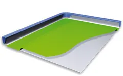
In conventional die hemming, the flange is folded over the entire length with a hemming tool.
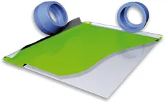
In roll hemming, the hemming roller is guided by an industrial robot to form the flange.
Conventional die hemming
Conventional die hemming is suitable for mass production. In die hemming, the flange is folded over the entire length with a hemming tool. Normally the actual hemming is a result of a forming operation in which the flange is formed with a hemming tool after the drawing and trimming operations have been completed. The formed flange is then hemmed in several process steps. These steps include, for example, the pre-hemming and final hemming depending on the respective opening angle of the flange. Production plants for conventional die hemming are very expensive, but the cycle times are very low.
Roll hemming
Roll hemming is carried out incrementally with a hemming roller. An industrial robot guides the hemming roller and forms the flange. Roll hemming operation can also be divided into several pre-hemming and final hemming process steps. Roll hemming is very flexible to use and tool costs are significantly lower as compared to those of conventional die hemming. However, the cycle times are much higher since the hemming is realized using a hemming roller which follows a defined path.
Corner reliefs are given on the corners so that when we create a hem it will not create a problem.
NCAP-
A New Car Assessment Program (NCAP) is a government car safety program tasked with evaluating new automobile designs for performance against various safety threats.
Every NCAP has its own protocol to crash-test and score cars, and so the results are not interchangeable. Euro NCAP, for instance, conducts full frontal, front offset, side impact and side pole tests.
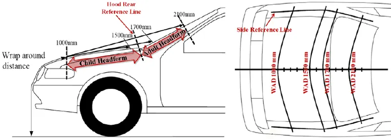
Now there also pedestrain safety test. For that there is a Wrap Around Distance which we need to calculate. When a car crashes on the pedestrain, the whole human body wraps around the front shape of the car and the head impacts on the bonnet or the windscreen. The distance on which the head impacts on the car from the ground is called as wrap around distance.
To be specific the Wrap Around Distance (WAD) is a measurement of a distance from the ground to the head impact zone over the outer surface of the car. The WAP is measured longitudinally in the centre of the vehicle from the ground.
During the crash analysis, based on the WAD, two test area will be created namely child head impact and the adult head impact zone. The child head impact zone is between 1000mm and 1700mm WAD and the adult head impact zone ranges between 1700mm – 2100mm WAD.
Then we give thickness to the inner panel and outer panel.
The inner panel and outer panel thickness lies between 0.65mm to 0.75mm.
The thickness of the reinforcement depends upon the requirement.
The features used for modelling are-
-
Offset surface
-
Offset curve in face
-
Trim sheet
-
Through curves
-
Projecte curve
-
Law extension
-
Trim and extend
-
Extend sheet
-
Face blend
-
Edge blend
-
Mirror geometry
-
Sew
-
Thicken
Offset surface - creates a body by offseting a set of faces.
Offset curve in face - offsets curves along the faces on which they lie.
Trim sheet - trims off a portion of a sheet body.
Through curves - creates a body through multiple sections where the shape changes to pass through each section.
Project curve - project curves, edges or points into faces or planes.
Law extension - creates a law controlled extension from a base sheet.
Trim and extend - trims or extends a set of edges or faces to intersection with another set of edges or faces.
Extend sheet - extend a sheet body by a distance or to the intersection with another body.
Face blend - add tangent blend faces between the selected sets of faces. The bend shape can be circular, conic or law controlled.
Edge blend - rounds sharp edges between faces. The radius can be constant or variable.
Mirror geometry - copies geometries and mirrors them across the plane.
Sew - combines sheet body by sewing common edges together, or combine the solid bodies by sewing common faces.
Thicken - creates a solid body by adding thickness to a set of faces.
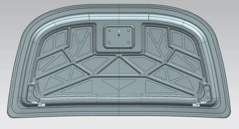
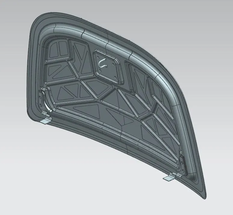
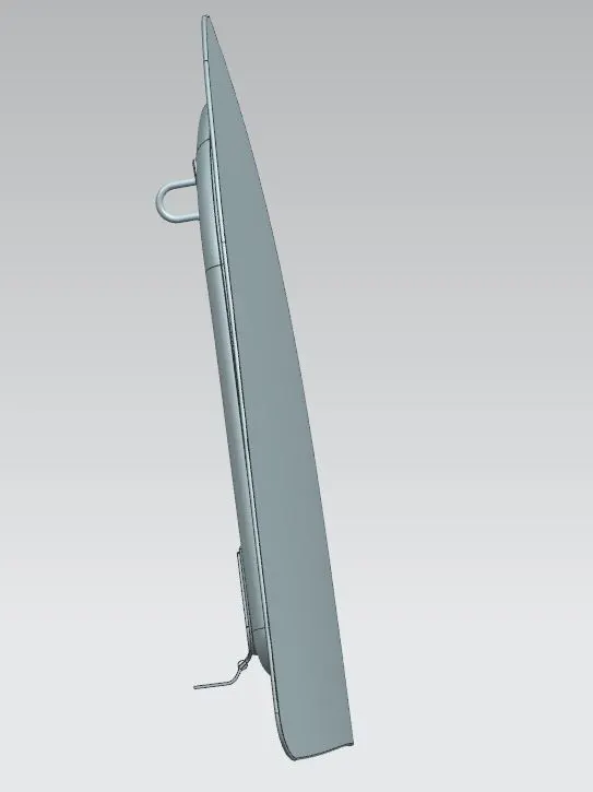
These are all the main tools used to create the hood assembly.
We also added some constraints for placing the parts properly in the assembly.
CONCLUSION
We were succesfully able to design the inner panel of the hood with the help of the given master sketch and other dimensions. We also designed the hood according to the NCAP regulations and the succesfully assembled the hood inner panel, hood outer panel,hinge, striker with their reinforcements. We were also able to understand the method behind designing the hood and manufacturing process behind it.
We also understood the varoius tools in nx cad for designing a model and its assembly.