Hood design-Week 2
Repot on Hood Assembly designing
On behalf of Hood assembly designing, First I have created an assembly file and named as “Hood Assy Main” followed on, outer panel part file was inserted by “Add” component. Then created inner panel part file by using ‘Create” option. By using “Wave geometry linker” Outer panel copy were transferred to Inner panel part file.
By activating Inner panel, offset surface has been created with 1.7 mm clearance, and hide the initial surface, made it as “Feature group” named as “parent”. From that I began the inner panel work as per below mentioned “Hood Master Section” given by Skill Lync.
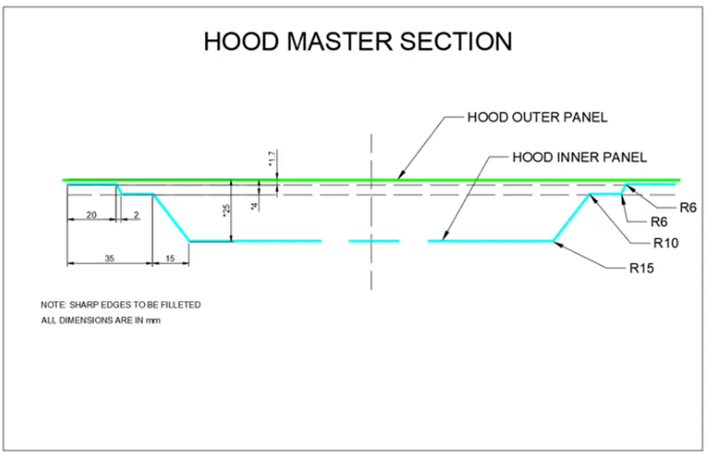
In that 1.7mm offset surface from Feature group, created an offset line of 20 mm in that same plane by using “offset in face”. By using “Trim Sheet”, outer part of face kept, and inner part were discarded. Then created another offset surface from “Feature group” of 4mm, and created two separate offset line in same face, at a distance of 22mm and 35mm. By using “Trim sheet” command, Outer most part and inner most part in the same face were deleted. For the final step, created an offset surface of 25mm from “Feature Group” and drawn an offset line in particular face with 50 mm. By using Trim Sheet command Inner part of face kept and balance were deleted.
“Through curve” was used to develop a joint between these separate layers, which were created earlier for hood inner panel creation. After creating the slope joints, all the parts of inner panel were joined together by using “Sew” command. By considering the Deep drawing process, need to develop the edges by using “Edge Blend”. It will help to create radial curve at the edges with specific radius. There is main two type of tools available to create radial edges, “Edge Blend” and “Face Blend”.
“The Edge Blend” Command only applicable if the parts are joint together by using “Sew” tool. In this tool, it can be able to select only one single edge and we can specify the radius. “The Face blend” is used to create radial edge by using two individual faces. Once gone through “Face blend”, there is no need of “sew” to make them together. Blend has created as per given Hood master section.
By considering the moment of inertia, that can be exerted in a hood by the collision with other equipment or pedestrians. The force has to be diverted towards Hinges or Sideways, to reduce the direct impact with passenger available in Vehicle.
A freestyle design can be adopted by design by himself. Create a datum plane, in that plane where we need to draw the design. By creating appropriate drawing in that plane, need to project the draw in our hood inner, using “Project curve”. After projecting the drawing, “Emboss” process will be undergone. The “Emboss” command will helps to deform the surface as per decide parameter. It gives a shallow/ Deep drawing feature in our 3D model. Only need to select the face, Select the boundary, offset value and the direction at which emboss must be done. Only need to be considered that, “Draft Angle” between 7-10 Deg. for machinability.
The Embossed surface undergo only through Edge Blend, because there is no separate Face available to do Face blend. The existing plane is converted into embossed surface. So, they will be single edge available. The edges must be minimum of 3 Deg for Die-punch combination. Both inner and outer Edges must be smoothened by using face blend.
Next the time to make Hinge reinforcement, before creating the emboss it should be considered that the Hinge assembly surface should be perfectly parallel to the reinforcement, because our Hood surface is slightly tilted from the beginning. So, need to construct a datum plane which is almost parallel to Hood inner panel. So, by use of Datum plane option, created a plane “at angle” orientation, around -7 deg. to maintain almost parallel surface and offset to distance to make the plane closer to hood plane.
After that an appropriate sketch was drawn in that plane and projected on hood assy, as said earlier. after that emboss was done and make sure the edges are smoothened.
“Mirror geometry” were introduced to make complete piece of hood. But eventually it was observed that, few gaps were developed between the two bodies. To eliminate the gap. Extended each sheet with 5 mm length and trimmed accurately with the help of appropriate perpendicular axis. After the Mirror geometry has completed successfully.
Introduced Hinge assembly in our assembly file by using “Add”. Using “Touch-Align” Constraint, Hinge hood side face fixed on Hood inner panel’s Hinge reinforcement area. “Mirror Assembly” tool will help to generate a separate and identical Hinge and placed on exactly the mirrored portion of hood inner panel.
Using “Point” option in “Curves”, 3D points can be marked for getting Hinge axis. By clicking “Point”, need to select “Arc/Ellipse/Sphere centre” to get rotating axis point of each Hinge. After that create a line by linking the two points, that is our “Hinge Axis”.
After hinge axis creation, Stricker to be introduced in our assembly file, using “Add” option. Latch and Stricker trajectory need to be developed by trail and error method, by drawing the circle in Hinge axis. Tangent line to be drawn approximately near to sticker placing area in Hood inner panel.
Activating “Stricker” assembly, a datum plane must be introduced appropriate position, where we can draw a perpendicular line for meeting the alignment of latch-Stricker trajectory. Using “Touch-Align” constraint, Stricker placed exactly in the same trajectory.
By using “Wave geometry linker”, the base of Stricker introduced in “Hood inner panel” part file. The face was extended upto 5mm. Using “Law extension” tool an extension has created towards hood inner panel. “Trim sheet” will help you to trim excess extension after hood inner panel. “Edge Blend” helps to create chamfer edge with a radius of 3mm in top and bottom edges.
Consider the hemming dimension, Hood inner panel surface offset inward with 2.6mm and best fit of 15 mm radius provide, so that the inner panel never come out, once we create ‘relief’ after hemming. And outer most portion deleted.
Before hamming, Outer panel sharp Edges need to be deleted. For that minimum offset need to be provided. After giving the smoothen curve, need to create a separate offset on same face considering the Hamming length(6mm), need to be covered by outer panel. As shown in Figure
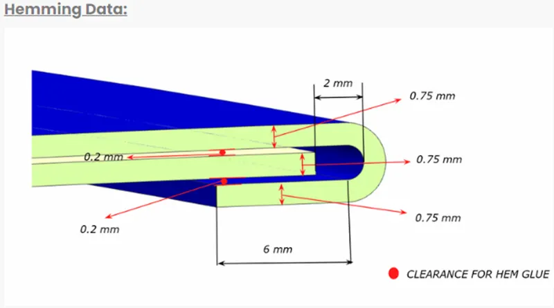
Using “Trim sheet”, remove the sharp edges in outer panel with the ‘minimum offset’. Law extension to create in both inner and outer offset surface with minimum vertical height of (0.75+0.2+0.75+0.2+0.75), as shown in figure. After creating the Law extension sheet (Symmetrical), offset surface has create from outer panel, so that we can create the bend portion of hamming. Offset surface will be at (0.75+0.2+0.75+0.2+0.75). by make the inner law extension face as boundary, inner part of offset surface to be removed, so that the 6mm bend will be clearly visible. Using “Face blend” “Three-Face” Option, the outer ‘law extension’ can be done like a bend sheet.
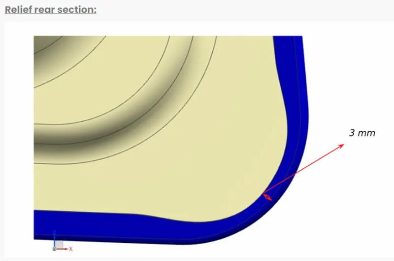
By considering edge rolling, relief section need to be provided at the corner of outer panel. Minimum of 3mm gap to be maintained as shown in figure. Using “Curve on surface” we can draw simple appropriate drawings to meet ‘relief section’ criteria.
Thicken all the inner and outer panel with a measure of 0.75mm as suggested in our project. Cross the hamming region and measure the distance, which are correct as per given criteria.
Once it is completed, Mirror the Geometry with help of “Mirror Geometry” and make the Sew. Extracted body can be created to finish each assembly.
Thank you,
Amal Francis C