Fender Design Challenge
Challenge 6:
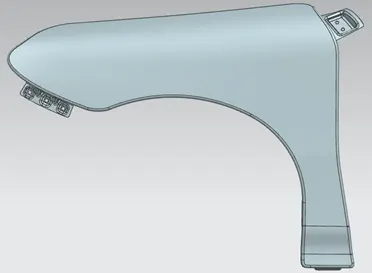
Fender Design
Fender
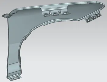
Fender is the US English term for the part of an vehicle body that frames a wheel. When vehicle is moving, tires pick up stones and others and hurl them in all directions. For that reason, its primary purpose is to prevent sand, mud, rocks, liquids, and other road spray from being thrown into the air by the rotating tire. Fenders are basically present to prevent any injuries to pedestrians and contain the motion of these particles. This anti-chipping is one of the pedestrian safety criteria because the stones which get chipped from the pair may tend to hit the pedestrian also. So, we would recommend having trunk fender, so that the pedestrians are also safe. Parallelly it also covers the engine compartment, so that you don’t see in an ugly region from the outside.
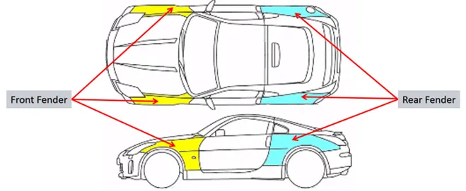
There are two types of fenders:
- Full Bumper Type
- Half Bumper Type
The conventional methodology is for the use of the basic type of fender which is Half Bumper type.
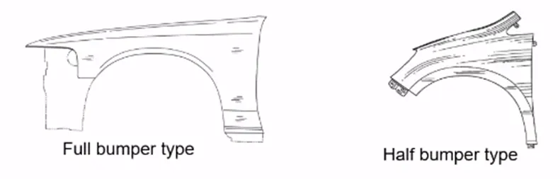
Half Bumper Type
Half Bumper type has a high possibility to reduce scrap. By slightly increasing the blank size, we can produce two fenders at the same time and reduce the material usage. Therefore, it will reduce the blank cost drastically, so that you’ll provide to customers a better fender for a cheaper price. In addition, this methodology will allow to use a lot of plastic on the bumper which means you are reducing some proportion of steel weight, so that you are also increasing the performance of the vehicle.
Fender Mounting Points
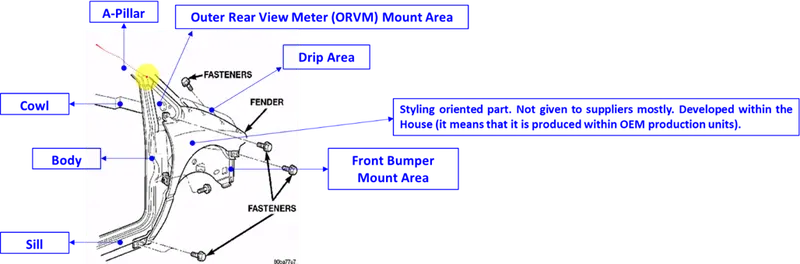
Fender is basically mounted in 5 different regions:
- Drip Area – Region which is in contact with the engine compartment. Here we use fasteners.
- Front Bumper
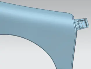
- A-Pillar
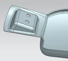
- Sill – Region which have the Spoilers Curse or Sill Outer which will hide the fasteners.
- Cowl – It is a plastic part where you have the wiper mounting regions installed.
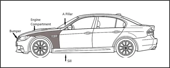
The main function of the fender is related to aesthetics and aerodynamics, however the first reason for their introduction was to shield wheels and protect passengers’ compartment from projection of water, mud, and stones.
In comparison to the body frame, the structural contribution of fenders is zero with the exception of a few cases (mainly spiders) where the front fenders are welded to the body frame in order to increase the overall torsion stiffness.
Usually, front fenders are only screwed on, while on the rear (quarter panels) they are welded to the body side.
Metal front fenders commonly comprise few parts: a main drawn panel, a back completion flanged to main panel, the purpose of which is to seal the space between fender panel and lower front pillar, and some brackets to fit the fender to body and hold accessories.
Figure below shows some typical fender to body fitting sections. Some fender properties are specified by manufacturers as standard such as:
- The fastening characteristics.
- The masked gap section.
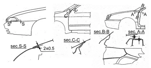
Examples of matching zones between the front fenders and body parts.
- The fitting of interior mudguards (Figure below). In this figure, the free distance available for fender crushing under pedestrian impact should be, according to standard approximation, at least 80 mm in order to limit pedestrian head acceleration.
The main advantages of detachable front fenders are:
- The fitting process for movable parts can follow a longitudinal path, starting from quarter panel and ending with front fender; in this way, a degree of lack of precision in body side or doors can be recovered.
- Fenders, mainly front, are frequently exposed to impact and damages. Consequently, the cost of repair is lower for fittings which are detachable.
- Fenders can be made from a different material than the body.
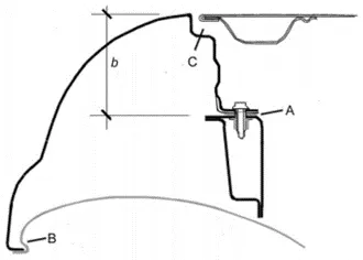
An example of fender and wheel opening section. A: fastening with spacer, screw, and riveted nut; B: Lokari R® fitting; C: masked gap; b: amount of deflection designed for pedestrian impact absorption.
The number, type, and position of fender fasteners to the front frame are specified independently by each car maker. The principal problems faced with fenders are linked to stone, sand and mud projections by wheels causing fender abrasion and annoying noise levels which can be perceived inside the cabin due to the high acoustic transparency of the metal walls over the relevant frequency range.
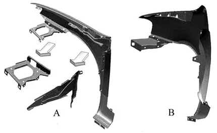
A) steel fender, showing the additional pieces before assembling; B) plastic fender.
Front Fender
It is one of the side closure components for the engine compartment. Its major role is to avoid chipping inside the engine compartment. During motion, the wheels raid to pick up some stand and mud particles and small stone particles and throw inside the car. The fender is very helpful in preventing them hitting inside the engine compartment. This fender will have a plastic part which is lying on this arc area. This is a big part which basically protects the engine compartment. This fender also plays a major role to prevent injuries for the pedestrian. This commodity is designed thinking about the pedestrians who are being attacked.
Manufacturing Process
Generally, the manufacturing of sheet metal involved following steps:

Fender Design
Design Parameters
The Drip Area is the most important factor for fender design.
- It is the joining between the fender and the engine compartment.
- It is the major and most important mounting.
- The connection of the fender with the engine compartment in drip area can vary for different cars. However, the design considerations are always the same through all the cars. The material is prepared in such a way that we have a standard design consideration that can be used for any OEM. So, the basic design considerations that you do express will really be similar between all OEMs.
1. Drip Area Dimensions
To develop fender drip are we need a Master Section like shown below:
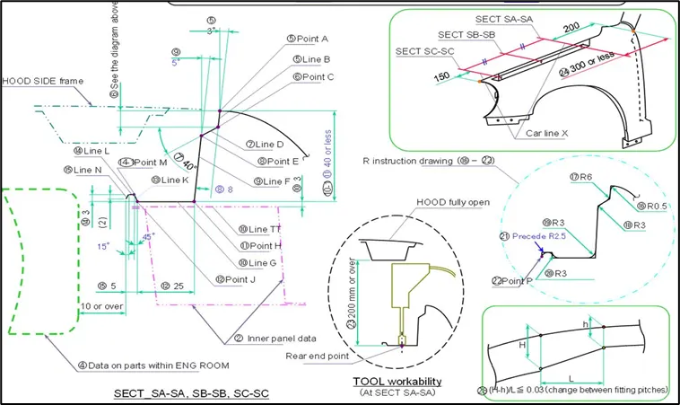
2. Drip Area Depth
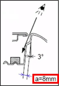
The design intention should be that anyone can see anything which looks bad inside the engine compartment. It will not be good to see the fasteners from the outside. When you see the hood outer panel and the fender from the outside you will find a small gap. The 9 mm minimum depth requirement ensures to have a gap that prevents the consumer the visibility inside (to see the fasteners or any other ugly area inside the engine compartment). This gap allows to create another 3° opening inner flange with a dimension “a” between 7 or 8 mm that defines dimensions for drip area.
3. Drip Area Distance
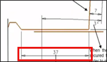
The minimum value for the final Drip Area Distance should be between 35 to 40 mm. The reason for this distance is for the tool to come and work perfectly inside. In this case, the dimension of 37 mm is the one that allows you to have the Hood opened condition in which you will mount your fender, and then you will have your tool to fix it. In the assembly sequence, you will have:
- The Body without the Hood.
- Then you will mount the hood on the hinges.
- Then, keeping the Hood opened condition, you will mount the fender with the help of the tool and to access this tool we need to have at least 200 mm gap. This distance of 200 mm will be just a reference to design.
However, we should make sure that there is no other part inside the engine room at least for 10 mm or you can even exceed the drip area distance. If that is the case, the requirement is the end most part which will be in contact with the fender drip area should have at least 10 mm clearance, so that it is not hot or damaged while assembling the part or the commodities inside the engine room. Then, with respect to this, you can vary the drip area distance.
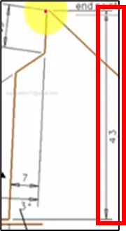
The 43 mm length is basically because of the tool that is producing the part. This tool will have the tendency to punch this deep, but if it goes more than this, it will be difficult to punch the part. The deeper, the more difficult the part is. Most of the tools cannot go more than 40 mm. So, this distance of about 40 mm is a kind of optimum value. If it exceeds more than 60 mm, the tendency is to get springback effect which means it may not meet the tolerances. When it is between 40 to 60 mm, it can be assured that it will not have springback effect. The values of 40 or 60 mm are defined based on the experience and based on the parent car.
Critical Values and Constraints to be followed for Fender Design
- Drip Area has a lot of design constraints to be followed.
- During the fender design, it is very important to determine the gap/clearance of the rear end and the front end of the fender. This is the first major thing that we need to understand to predefine the fender drip area length.
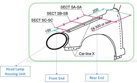
- The Cowl Top part will be carrying wiper motor and its instruments. To have sufficient mounting space for this Cowl Top, it’s needed minimum 200 mm. So, when designer starts preparing the fender drip area, this 200 mm should be taken and then start my drip.
- Similarly, we are going to be a head lamp in front end. This head lamp will have a housing unit. The housing unit need at least 150 mm to have sufficient place.
- When the cowl top becomes smaller than the conventional ones, the rear end clearance can be reduced, but on most of the cases we have 200 mm for rear end and 150 mm for front end. The remaining intermediate length will be fender drip area.
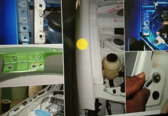
Several examples of Drip Area Mountings for different cars
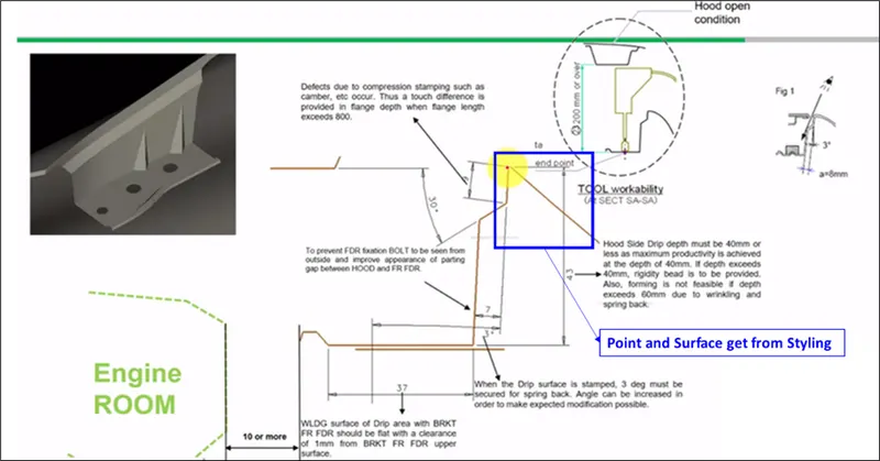
In the Master Section we should go as deep as 3 mm inside with an opening angle for 3°. This opening is given because if it is less than 3°, for example, if the fender is straight, it would be difficult for production purposes. So, to avoid that, we should follow an opening angle with a minimum of 3º because that is how the tool will work.
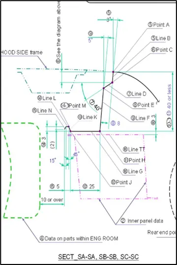
Drip Area Design Report
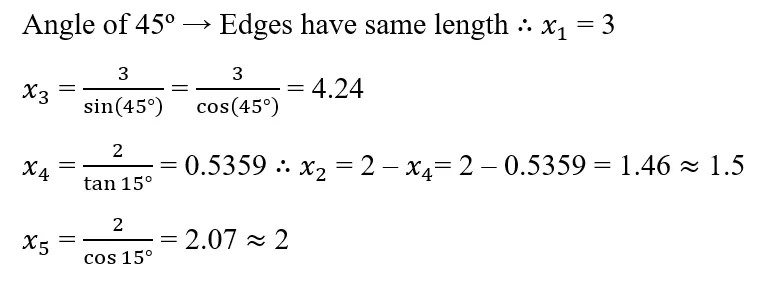
Based on the previous definitions of Drip Area parameters, the remaining dimensions were calculated as follows:

Drip Area Mounting
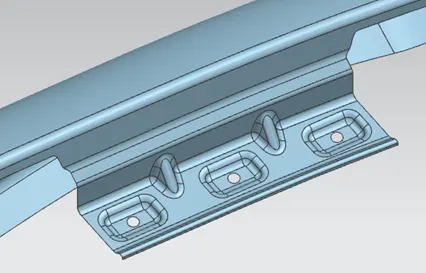
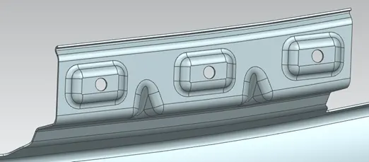
Front Bumper Mount Area
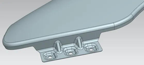
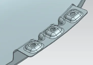
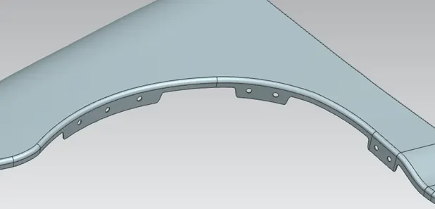
Wheel Mud Baffle (Splash) Mount Areas
This is an additional part that is added to Diesel vehicles only for Indian cases. However, in other regions, this is added for all versions. This part is added to improve the NVH (Noise-Vibration-Harshness) behavior, which is critical topic. This is mounted on the fender to absorb all the noise that is coming from the engine compartment. It reduces noise and vibration into the cabin which increase the passenger's comfort inside the car. This may be present in some cars, but not in some other cars. If we are going to add a baffle, it is needed to provide some more mounting points. The wheel arc area is the region in which you will be mounting the baffle, which is a plastic part.
A-Pillar Mount Area
Sill Mount Area
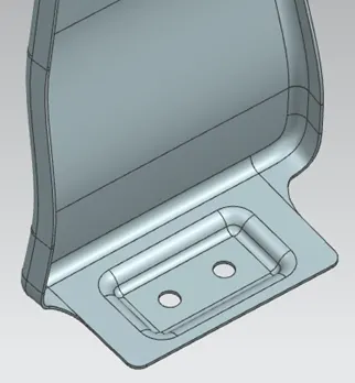
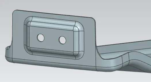
Design Parameters and Constraints
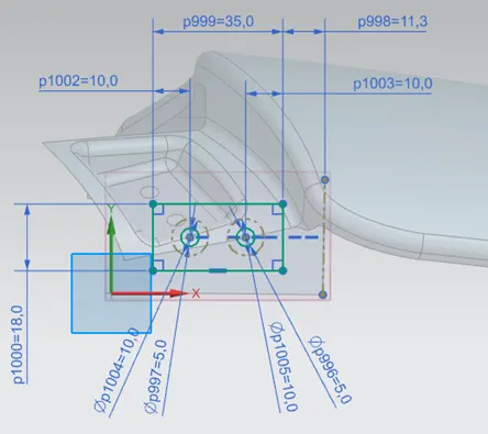
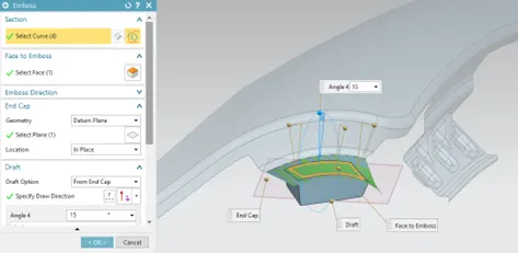
1. Flat Area Gap for Fastener Mounting
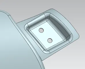
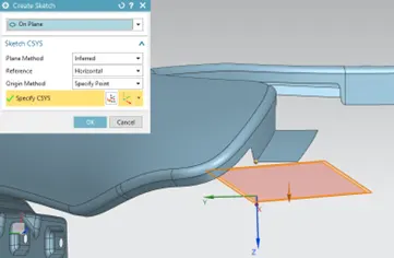
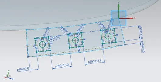
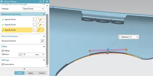
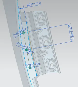
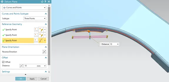
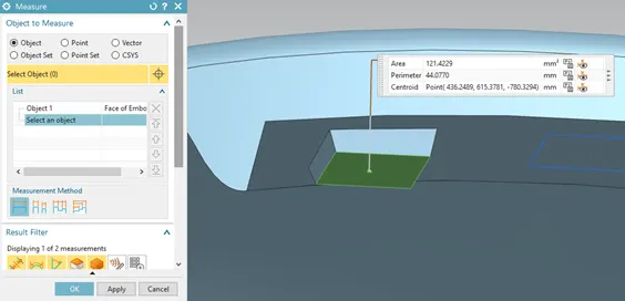
Provision of a 5 mm hole is needed to all the fasteners was used for the mountings. In addition, a proper surrounding gap of 3-5 mm needs to be created around the features for the tool to do the required operation and to avoid stress concentration.
Bumper Mount
A-Pillar Mount
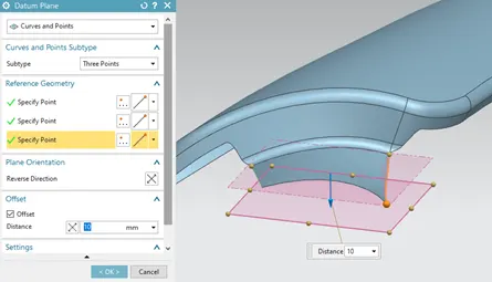
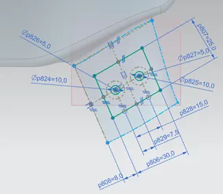
Sill Mount
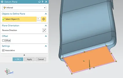
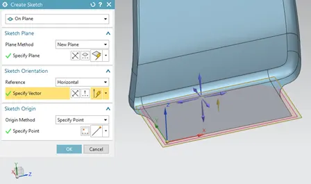
Baffle Mount
Here it’s not needed to create an emboss, just holes will be enough. Because this is the flash cover mounting place and the flash is mounted with plastic clips, and it's a rubbery part, so no need for a flat surface.
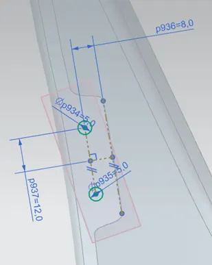
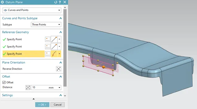
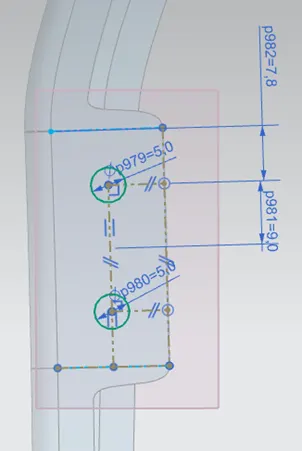
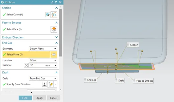
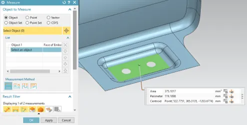
2. Flat Embosses
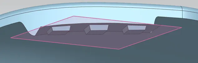
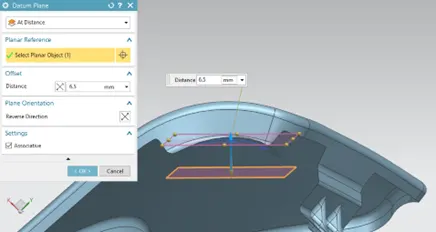
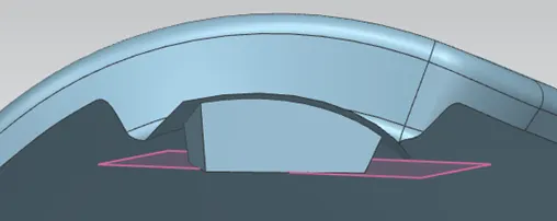
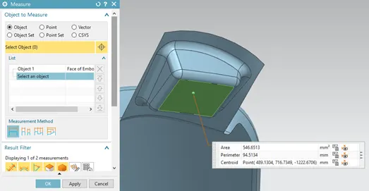
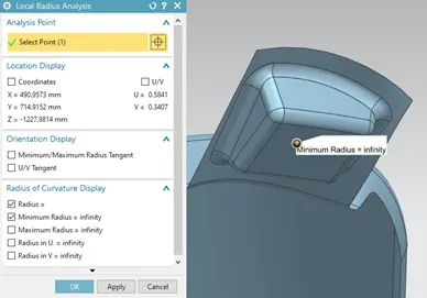
All the embosses were provided with more than 3mm depth and flat surface for fasteners.
Bumper Mount
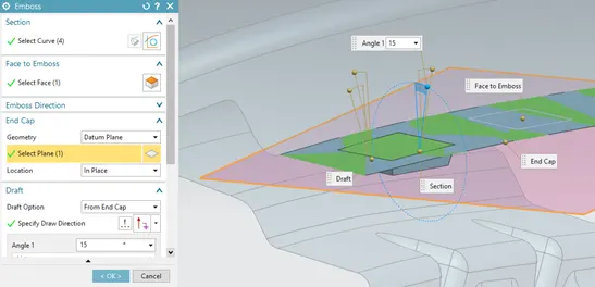
A-Pillar Mount
Sill Mount
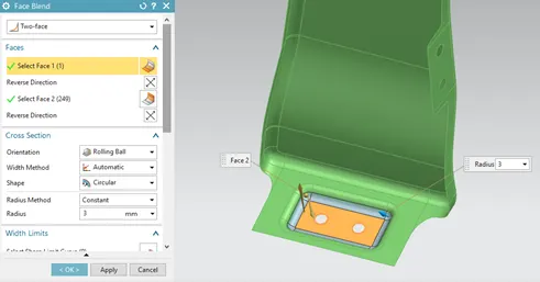
3. Minimum Fillet Radius
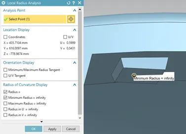
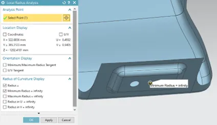
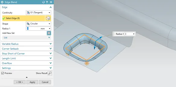
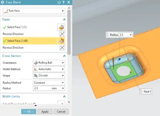
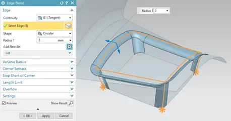
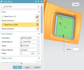
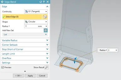
It is recommended that the blends given for the embosses are more than 3 mm. The minimum radius that you give to all the corners will be 2.5 mm. This value is provided because it helps to improve the aesthetics and the pedestrian safety. When the 2.5 mm value is reduced, we tend to make the corners sharp which is again a problem for the pedestrian. Also, in the model it might cause thickening issues. So, it is needed to maintain at least 2.5 mm to have a better pedestrian safety fender.
Bumper Mount
A-Pillar Mount
Sill Mount
4. Ribs
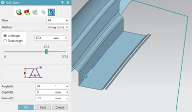
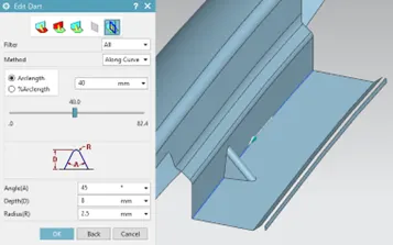
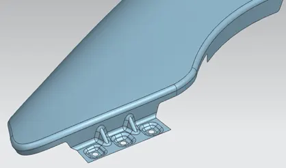
Strength was given to drip and bumper mountings with the help of ribs as it is acting as a cantilever beam because of their dimensions. Dart feature was used while creating these ribs.
Drip Area Mount
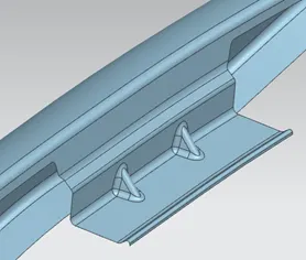
Bumper Mount
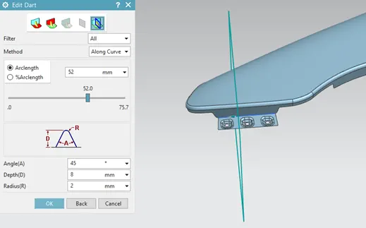
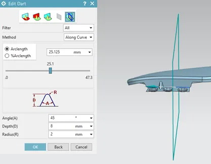
5. Reliefs
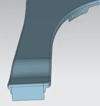
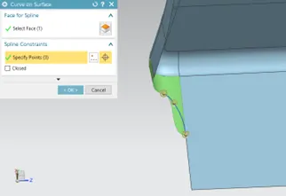
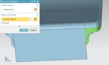
Reliefs were provided for sharp and ugly corners.
Sill Mount
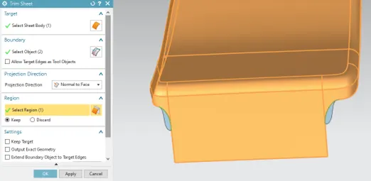
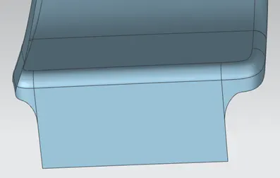
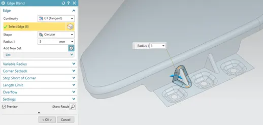
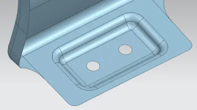
6. Rounded Corners
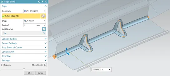
It was provided 3 mm corners in some locations.
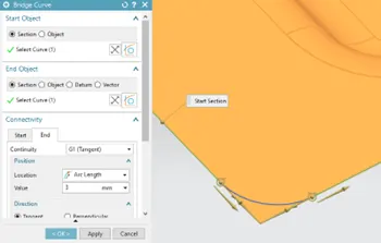
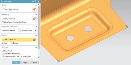
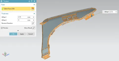
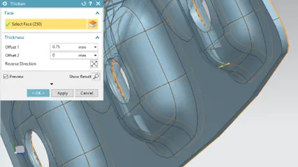
7. Thickening
It was provided a thickness of 0.75 mm inwards to the final surface.
REFERENCES
- Davies, G - Materials for Automobile Bodies - Elsevier (2012).
- Rowe, J - Advanced Materials in Automotive Engineering - Woodhead Publishing (2012).
- Genta, G., Morello, L., Cavallino, F., Filtri, L. - The Motor Car – Springer.
- Morello, L., Rossini, R., Pia,m G., Tonoli, A. - The Automotive Body Volume I: Components Design - Springer Netherlands (2011).