Hood design-Week 2
OBJECTIVE
To design the hood outer panel, inner panel and the necessary reinforcements by following the master section.
HOOD
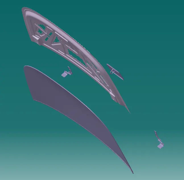
Hood is the hinged cover that rests over the engine of a front-engine vehicle. Its purpose is to provide access to the engine for repair and maintenance. The hood system consists of an inner panel, outer panel, hood stay, latch and hinge assembly The hood is critical component because of frontal crash and pedestrian safety requirement. The hood dissipates the car energy outside. The hood stay is an apparatus for an engine room of a car, which can safely keep an engine hood in an open state even if an external force is abruptly generated due to wind, vibration and can facilitate an opening/closing operation of the engine hood
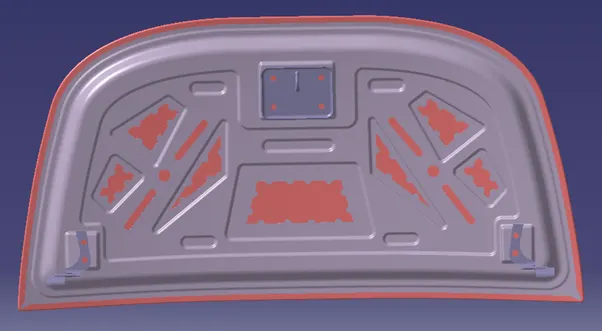
Fig 1. Hood Asembly
1) Inner and Outer Panel
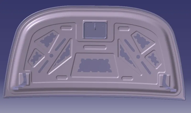
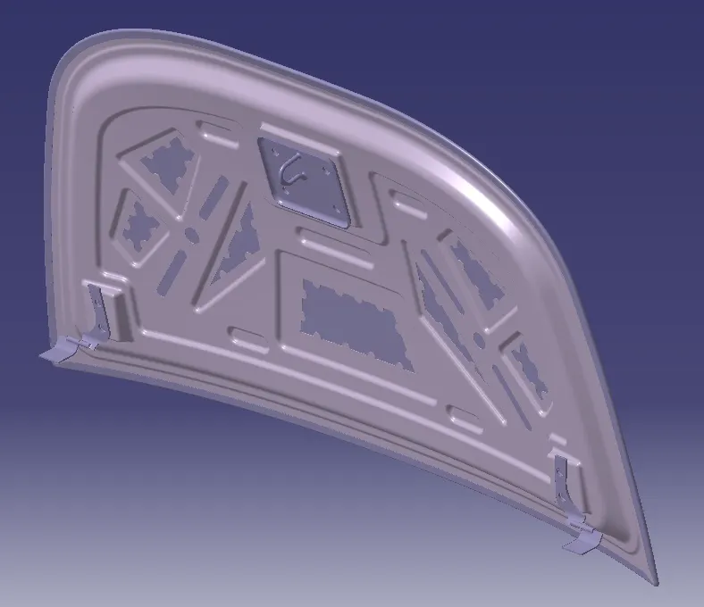
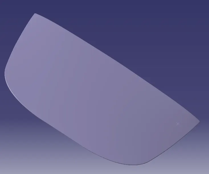
The inner panel provides the strength while the outer panel functions as metal cover. Both the pannels are of 0.75 mm thickness individually. The pannel embosses are done along v & y direction to dissipate the force equally. Embosses are designed as a guide for the force to travel and dissipate the force away from the passenger to the outside of the car thereby reducing the impact. When embossed, the sheet metal loses its strength so to compensate, it is reinforced.
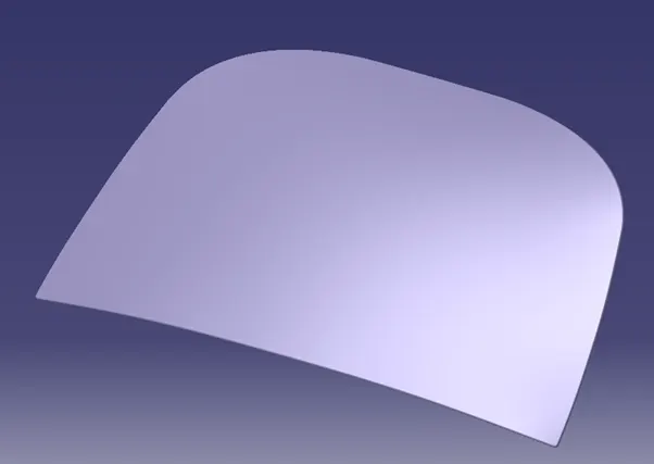
Fig 2. Outer Panel
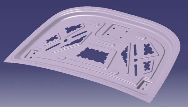
Fig 3. Inner Panel
2) Mastic Sealants
They are used between the inner and outer panel of the hood. It has the tendency to increase the strength locally around 80 mm diameter. The gap between the outer and inner panel will be approximately 5 mm, which will be filled by the mastic sealants which are made of hard rubber.
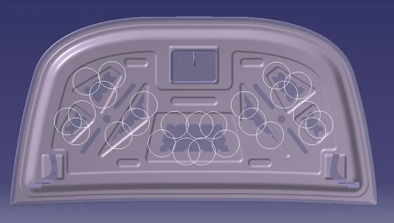
Fig 4. Mastics
3) Hinge and Latch
Hinges are responsible for the opening and closing of the hood while the latch and striker are the locking mechanism of the hood
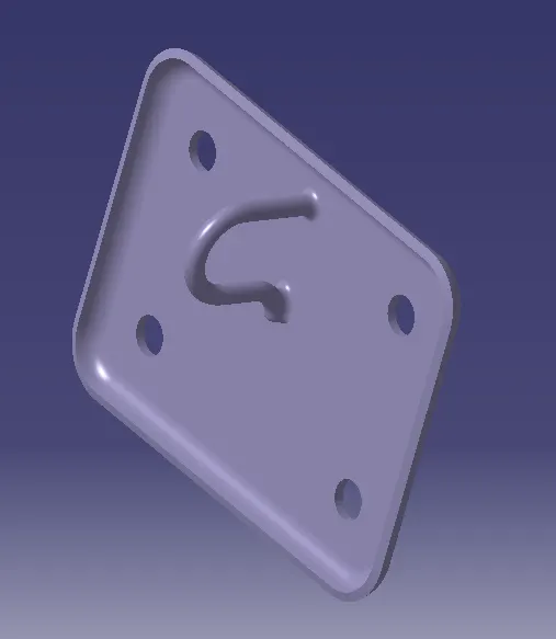
Fig 5. Latch
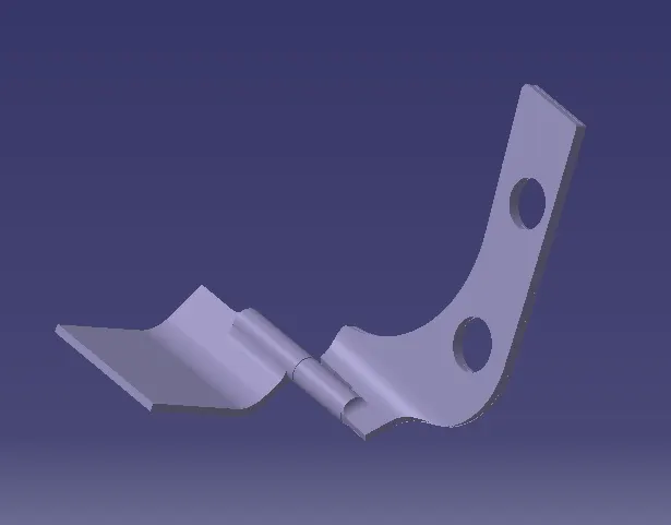
Fig 6. Hinge
The hinges have an axis and the hinges are positioned tentatively. The hinge axis point should be aligned with the striker through the trajectory of the hood opening and closing. If the striker is exactly perpendicular to the trajectory, then the hinge can be fixed accordingly on the inner panel.
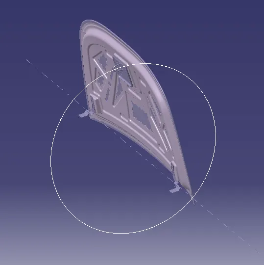
Fig 7. Trajectory
4) Master Sketch
The geometry is created based on the master section. The maximum distance between the inner pannel and outer pannel is 25 mm
Fig 8. Master Sketch
5) Hemming
Hemming is done to close the gap between the inner and outer panel which will be around 0.2 mm to avoid spot weldings. The hem is applied with sealant to achieve water tightness.
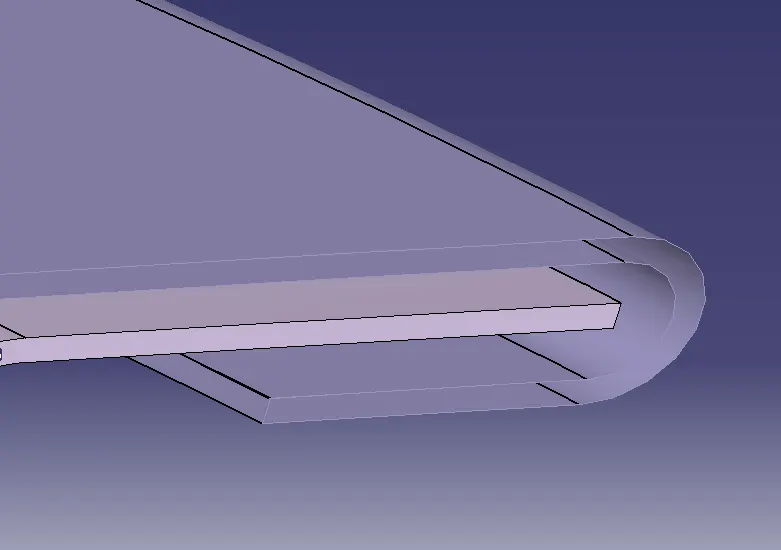
Fig 9. Hem
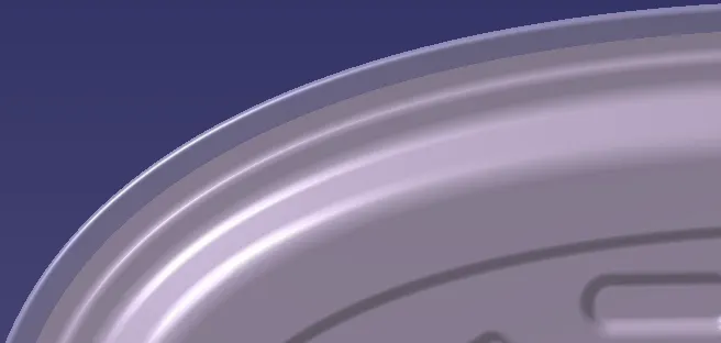
Fig 10. Overall Hem
6) Hem Relief
Relief is provided on the hem corners to avoid intolerance issues arising from the process of the rolling in hemming operation
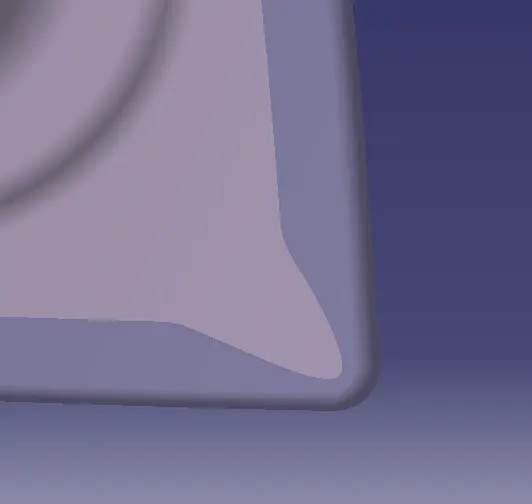
Fig 11. Hem relief
VIEWS OF THE HOOD