Advanced Sheet Metal Design Using NX Cad Challenge_1_Casing Design
CASING DESIGN
Objective
To design a sheetmetal casing using Siemens NX sheetmetal application
Introduction
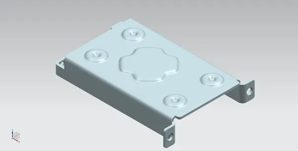
Casing is designed using application-oriented features such as beads, dimple, bend, flange etc.
Design methodology
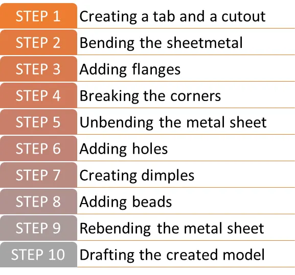
Description
Step 1: Creating a tab and a cutout
Features Used: Sketch, Tab & Normal Cutout
A rectangle is sketched of dimensions 60×50 mm and converted into a tab of 1 mm thickness. A sketch of 5×40 mm is drawn on the face of the tab and cut out with the through all option.
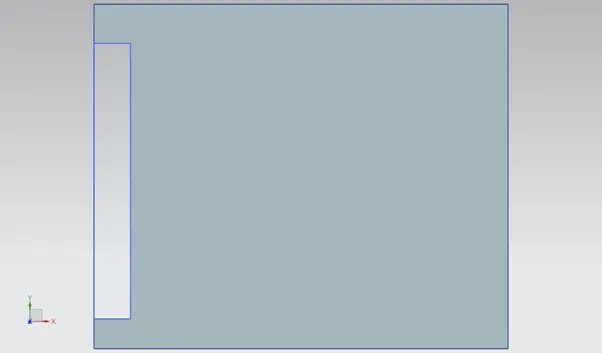
Figure 1.1
Step 2: Bending the metal sheet
Features Used: Sketch & Bend
Two horizontal lines are sketched on the plane. The upper line is at a distance of 10 mm from the upper left corner of the sheet and the lower line is also at a 10 mm distance from lower left corner. The sheetmetal is bent 90° at both the lines.
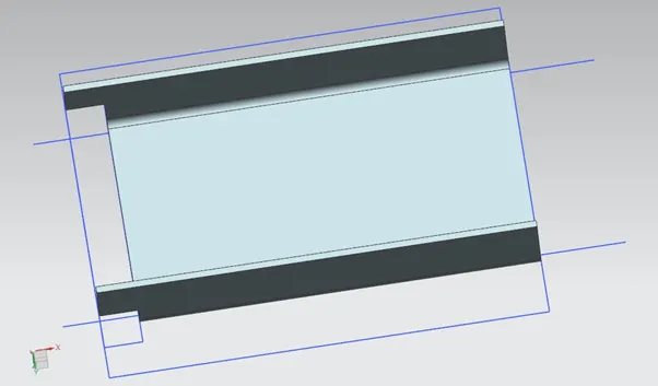
Figure 1.2
Step 3: Adding Flanges
Features Used: Flanges
Flanges of 5 mm are added to edges of the sheetmetal and reversed where required to obtain the result.
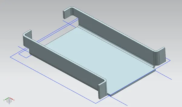
Figure 1.3
Step 4: Breaking the corners
Features Used: Break corner
Blend method of break corner is used with a radius of 1 mm to round or chamfer the sharp edges of the flanges.
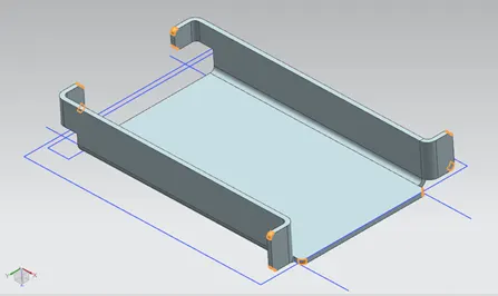
Figure 1.4
Step 5: Unbending the metal sheet
Features Used: Unbend
To unbend the sheetmetal the large horizontal face is selected as the stationary face and the adjacent face i.e. bent areas are selected as bend face. The flange edges are also selected to flatten them.
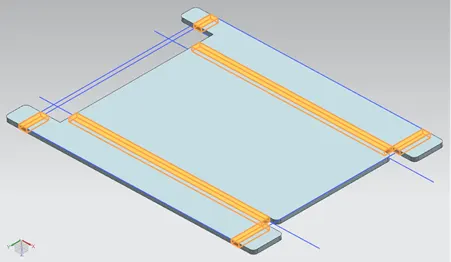
Figure 1.5
Step 6: Adding holes
Features Used: Sketch & Hole
Four circular geometry are sketched on the four flanges to create holes. Horizontal lines are drawn on the flanges and points are placed on the center of each lines. Using the hole feature with screw clearance hole as type, M2 as size and H13 as the fit the screw holes are created.
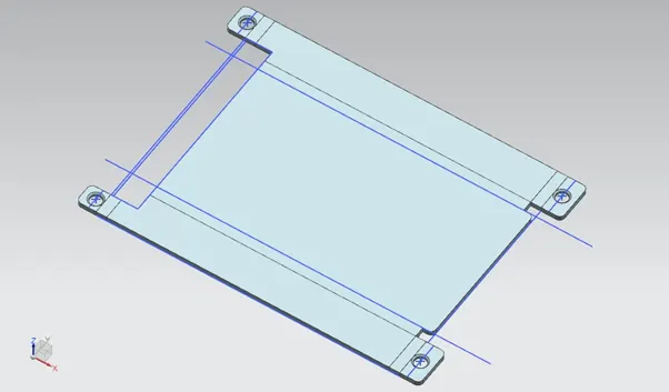
Figure 1.6
Step 7: Creating dimples
Features Used: Sketch, Mirror & Dimple
On the xy-plane a cross sketch with each half side as 5 mm in length is sketched at the origin (0,0,0) and mirrored. A studio spline with pole type and closed degree is used and all the 16 points are selected individually in clock wise direction. The created spline is selected by the move cursor option with an angle motion of 45°.
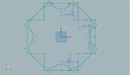
Figure 1.7
A dimple of 1 mm depth, side walls as material inside, punch, die and corner radius of 1 mm is created by choosing the spline as curve as in Figure 1.8
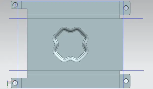
Figure 1.8
Step 8: Adding beads
Features Used: Mirror & Bead
On the xy-plane a circle of diameter 5 mm is drawn and selected as the curve for creating the bead. The bead is of circular cross section with depth and radius as 1 mm, It is then mirrored along the xz and yz plane.
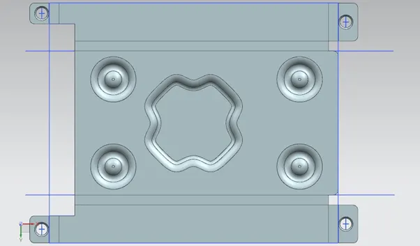
Figure 1.9
Step 9: Re-bending the sheetmetal
Features Used: Re-bend
The sheetmetal is re-bend by selecting them in the reverse order they were selected to unbend.
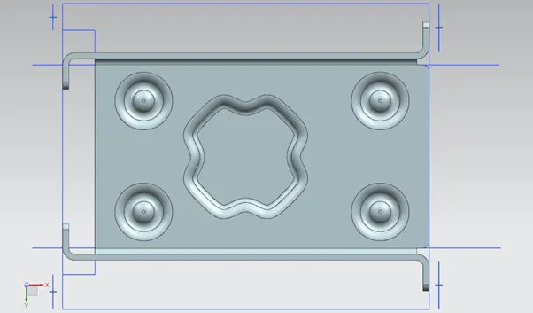
Figure 1.10
Step 10: Drafting the created model
Features Used: Flat pattern & Draft
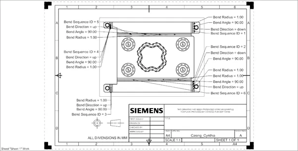
The central face of the sheet metal is selected for flat patterning. The flat pattern is drafted for A4 size and a scale of 2:1 in basic view.
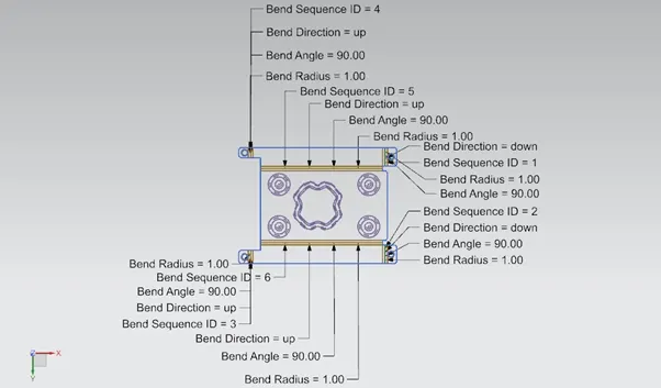
Figure 1.11
Model Images
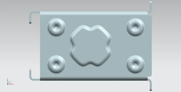
Top View
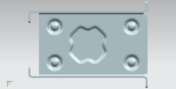
Bottom View
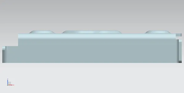
Front View
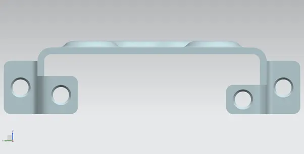
Side View
Isometric View
Drawing Sheet Image
Conclusion
The casing is designed and drafted using the Nx-cad.