Advanced Sheet Metal Design Using NX Cad Challenge_2_Box Assembly
BOX ASSEMBLY
Objective
To design a sheetmetal box assembly using Siemens NX application.
Introduction
Box assembly is designed using application-oriented features such as beads, dimple, bend, flange etc.
Design methodology
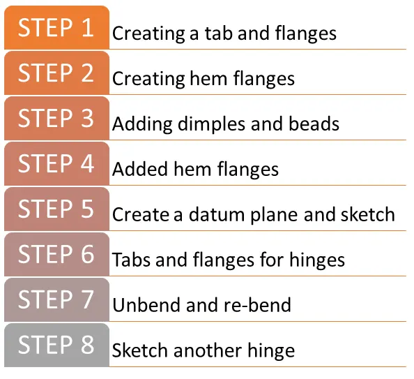
Description
Step 1: Creating a tab and a flanges
Features Used: Tab, flanges & closed corner
A rectangle is sketched of dimensions 200×150 mm and converted into a tab of 1 mm thickness. 200 m length flanges are added to it in the direction of xy-plane. Another 70 mm length flanges are added in xz-plane direction and their edges are closed cornered.
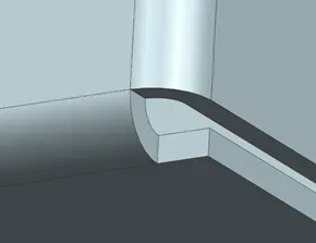
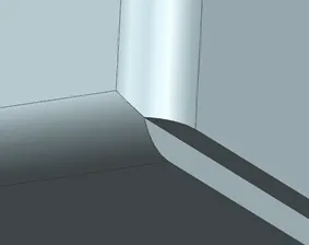
Figure 1.1 Before closing corners Figure 1.2 Closed corners
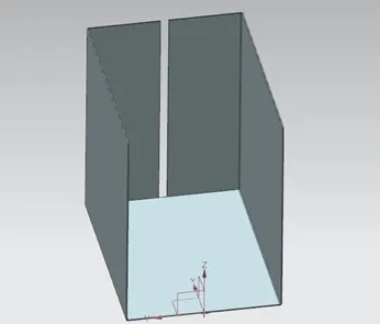
Figure 1.3
Step 2: Creating hem flanges
Features Used: Flanges, hem flange, Mirror & Unite
Two flanges of bend radius 0 mm, length 0.02 mm and 6.5 mm are created on each ends of the previous flanges (Fig 1.4) and are hem flanged for a bend radius of 0.5 mm and length of 5 mm (Fig 1.5). They are mirrored and combined as a single body using the unite command (Fig 1.6).
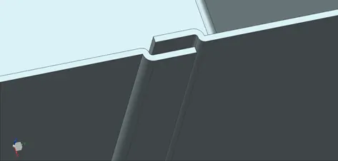
Figure 1.4
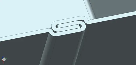
Figure 1.5
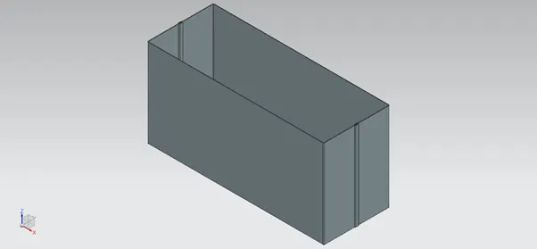
Figure 1.6
Step 3: Adding dimples and beads
Features Used: Dimple, mirror, beads and hem flanges
A dimple is sketched on the side face with a depth of 2 mm and mirrored to the other face.
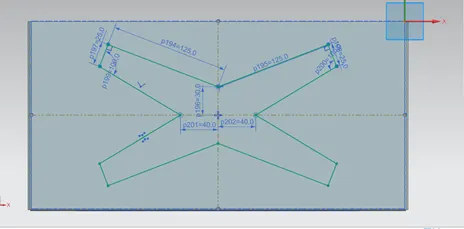
Figure 1.7
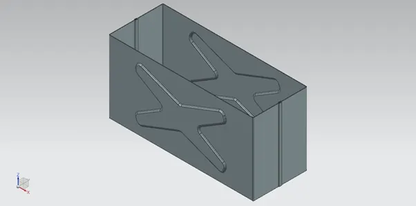
Figure 1.8
Rectangular dimple of depth 2 mm and circular beads of 5 mm diameter are created on the bottom face (Fig 1.9) and hem flanges are added on all top six edges (Fig 1.10).
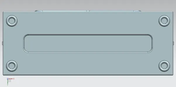
Figure 1.9
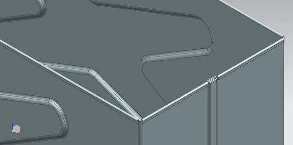
Figure 1.10
Step 4: Create a datum plane and sketch
Features Used: Datum plane, tabs & flanges
A datum plane on the xy –plane with an offset of 203 mm is created and an outline of the box is sketched for the lid. The edges of the lid are flanged for 3 mm length.
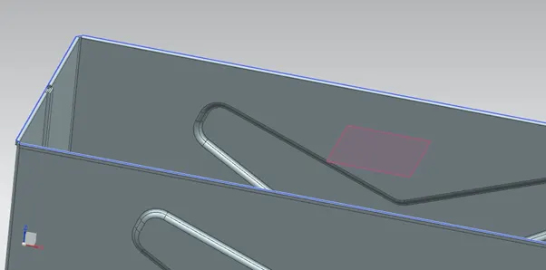
Figure 1.11
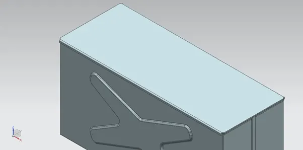
Figure 1.12
Step 5: Tabs and flanges for the hinges
Features Used: Tab, break corner, flange & hem flange
A tab of 55×20 mm and flange of 4 mm & 40° are break cornered for 10 mm. it is then hem flanged for a bend radius of 5 mm and sweep angle of 325°.
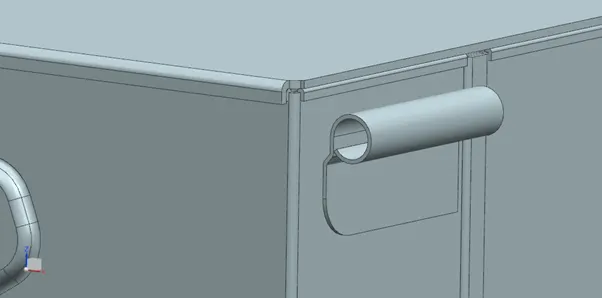
Figure 1.13
Step 6: Unbend and re-bend
Features Used: Unbend, normal cutout & re-bend
The tab is unbent and sketches are draw to cut them out (Fig 1.14) and re-bend. They are then mirrored to the other side (Fig 1.15)
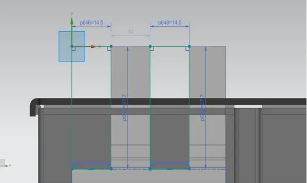
Figure 1.14
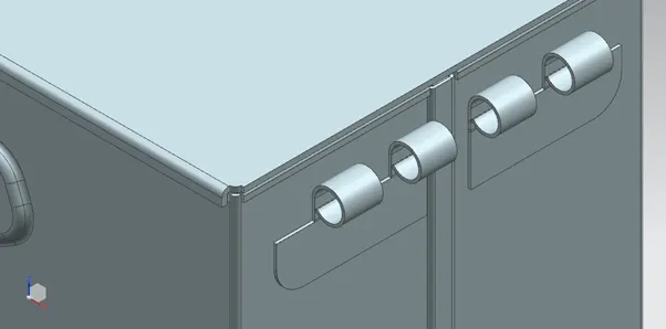
Figure 1.15
Step 7: Sketch another hinge
Features Used: Tab, flange & normal cutout
Another set of hinge is sketched on the face of the lid. The tab and of 126×23 mm dimensions and flange of 15 mm and 47° are unbent and sketched for the hinges which is then normal cut (Fig 1.17)
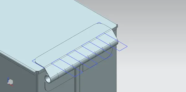
Figure 1.16
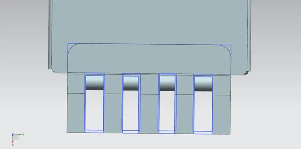
Figure 1.17
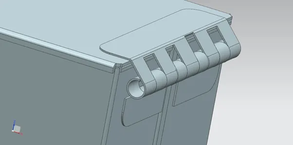
Figure 1.18
Model Images
Top View
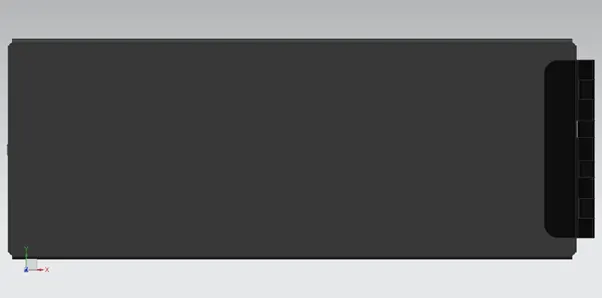
Bottom View
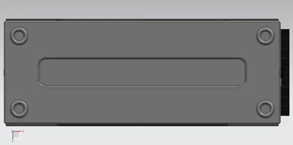
Front View
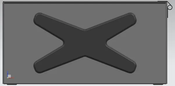
Side View
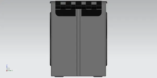
Isometric View
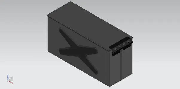
Conclusion
The box assembly is designed and appearances are applied using the Nx-cad.