Hood design-Week 2
HOOD DESIGN USING SIEMENS NX CAD
Objectives
- To study the modelling of the hood from received skin data of Class A surface and its requirements as per Euro NCAP standards.
- To study the surface modelling technique and its application to BIW parts using NX-CAD.
- To study the positioning of latch and striker and the required reinforcements.
Introduction
The car's hood consists of an inner and an outer panel. The inner panel provides strength, while the outer panel is just a metal cover. The underside of the hood is often covered with a sound-absorbing material. Some high-performance cars have 'hood scoops' that channel outside air directly to the air filter, which gives improved performance and efficiency.
Designing the hood is always a challenge as it is the first portion that comes in contact with the forces of air. The aerodynamic shape is always preferred for the front portion of the car because it gives benefits like less area of contact and hence, less resistance to motion. Further, the aesthetic design of the hood is also a factor of consideration as the user preference for the luxurious look of the car is increasing day by day.
In this project, we will be focusing on designing the Inner Panel and Outer Panel of the hood and finally assembling them with the given hinge assembly, Striker, and the necessary reinforcement.
Since we are initially using data from the class-A surface for designing, the modelling is done majorly using Surface Modelling tools.
Design of Hood
The design of the hood consists of the following parts:
- a) Internal hood structure
- b) Outside panel
- c) Engine body and hood hinge reinforcements
- d) Latch reinforcements
Components of Hood
- Outer Panel: -
A panel that covers the inner panel and engine compartment is called the outer hood panel. We consider this as a Class A surface because it is visible to the user hence it is given a very dedicated focus by the styling team. The panel has more aesthetic features but at the same time, it should be aerodynamic to avoid resistance from air. It is the first component that is subject to any type of impact so from the safety point of view, it is important to have good strength and ability to absorb impact.
This part is intact with the inner panel so to have a perfect combination its edges are wrapped around the inner panel and this type of wrap is called hem. Hemming is required because of aesthetic design as there is another no process that gives the desired result.
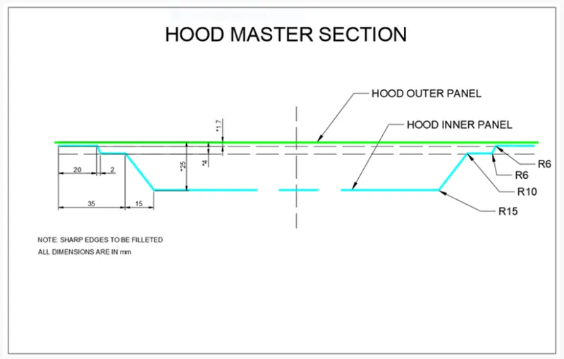
Class A Surface refers to those surfaces which directly visible to us and abide by the physical meaning of a product. These surfaces were designed by the styling team and a master section was prepared from them.
- Inner panel: -
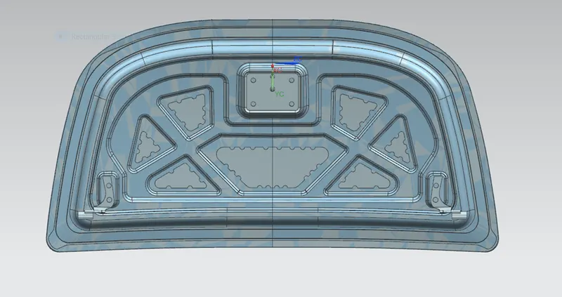
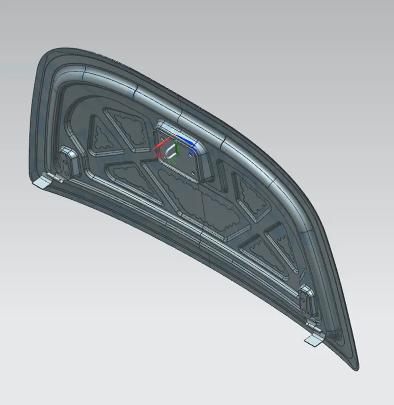
This is a class B surface that is not visible to the user directly. The design of this part has more engineering specifications such as stiffness, and impact force distribution design. The components attached to this panel are the striker and the hinges. This part is internal to the outer panel and designed to support it, hence the design of the inner panel is prepared from outer panel skin data which is received from the styling team. This has various emboss which are formed through forming process to provide stiffness and avoid the localization of forces. Its design is intended to distribute the force of impact to body pillars.
- Hinge and hinge reinforcements: -
Hinges are used to connect the hood and fender and permit a rotational movement to the hood to open and close the hood frequently. Technically they are provided to allow rotational movement of parts about an axis. They allow only one degree of freedom.
Embosses are created to attach the hinges to the hood but this reduces the strength of the section so to compensate for this loss, reinforcement is provided.
- Latch and Striker reinforcements: -
A latch and striker mechanism is used to lock the hood to the frame or body. Reinforcement is provided to compensate for the loss of strength.
Design considerations to be followed:
- Passenger safety.
- Pedestrian Safety.
- Manufacturing Feasibility.
- Positioning the striker along the Trajectory of the Centre of Hinge axis.
- Joining techniques of the inner and outer panel.
Design inputs:
Hood Thickness Information
- Outer Panel Thickness = 0.75mm
- Inner Panel Thickness = 0.75mm
- Reinforcement Thickness = 1.5mm
Tools used in the design process
Surfaces tools- offset surface, trim surface, face blend, edge blend, law extension, thicken, sew, etc.
Curve tools- curve on surface, project curve, offset curve, offset curve on surface, etc.
Feature tools- Emboss, mirror geometry, wave geometry, etc.
- Offset Surface: This command is used to create a surface or a body by offsetting a set of faces.
- Offset Curve on Face: Offsets curve along the faces on which they lie.
- Trim Sheet: Trims off a portion of a sheet body.
- Trim and Extend: Trims or extends a set of edges or faces to the intersection with another set of edges or faces.
- Extend Sheet: Extends a sheet body by distance or to the intersection with another body.
- Trim Body: This command is used to trim a portion of a body along a plane or a face.
- Through Curves: Creates a body through multiple sections where the shape changes to pass through each section.
- Law Extension: Creates a law-controlled extension from base sheet, dynamically or based on laws for distance and angle.
- Face Blend: Adds tangent blend faces between a selected set of faces based on the radius specified.
- Edge Blend: Rounds sharp edges between faces based on the radius specified.
- Project Curve: Projects curves, edges, or points onto faces or planes.
- Emboss: Modifies a body with faces made by projecting a section along a vector, with options for end cap location and shape.
- Curve on Surface: Creates a surface spline feature directly on a face.
- Wave geometry linker: It is used in this project to to replicate parts from other components.
- Mirror Geometry: Copies geometries and mirrors them across a plane.
- Sew: Combines sheet bodies by sewing common edges together, or combines solid bodies by sewing common faces.
- Thicken: Creates a solid body by adding thickness to a set of faces
Designing Of Hood
- Process of designing of hood starts from the styling team, they get updates about the preference of consumers to the overall design of cars and changing market trends from the marketing department. The styling team provides Class A surface data to hood designers.
- As per the Class A surface data, the preparation of the master sketch is done which is used in the design of Hood.
- A surface is extracted from the dump body surface. This surface is then termed as working surface, and further work is done using this surface.
- In the assembly environment of NX the part files of the inner panel, striker, and hinges are imported. The surfaces are symmetric, so we take half of the surface for working for convenience.
- First the working surface is offset by 2mm and then using the offset curve in surface feature, curves matching the edges are replicated to trim the surface.
- Further offset surfaces are created at 4mm and 25mm as per the master sketch from the working surface. The 4mm offset surface is then trimmed by using the curve on surface feature as previously but at a larger distance as per the master sketch.
- A through curve option is used to connect the first two surfaces and the remaining surface will be joined using the law extension of the surface that was trimmed. Thus, a base geometry of the inner panel is created.
- Then faces are blended using the face blend command as per the given data.
- Further some embosses are created on the last surface considering the safety parameters using a sketch leaving the space for the striker and hinge placement and then projecting it on the surface using the project curve option.
- Emboss option in NX is used to create emboss using the projected sketch on the third surface for an offset of 10mm and has a draft angle.
- Further embosses are created on the surface using sketch profiles in such a way that the force of impact will be directed towards the hinge.
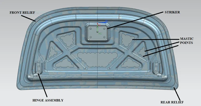
- Material is removed using the trim sheet operation taking into consideration, the safety criteria. The embosses would compensate for the loss of strength due to material loss. Some provisions for inputting the mastic points are provided.
- All the sharp edges are blended using the face blend or edge blend command to get a smooth surface and to avoid stress concentration. A minimum of 3mm radius is used for blends.
- From the assembly manager the assembly is activated, and the hinges are positioned near the inner panel using the move component feature. A parallel relation is given between the centre axis of the hinge and the X-axis of the work coordinate system.A plane is created parallel to and in the inner panel and near to hinge space.
- Emboss for the hinge assembly is created and blends are given.
- Thereafter the sheet geometry is mirrored about the symmetric plane using the mirror command and the two sheet bodies are joined using the sew command.
- The assembly is activated from the assembly navigator. An assembly relation-touch is provided between the hinge surface and the hinge emboss. The hinge assembly is then mirrored with the associative copy option about the symmetric plane. Using the wave geometry feature, the curves from the hinges are traced and a centre point is obtained for both the hinges. A line is created between the centre points of hinges and made parallel with the x-axis.
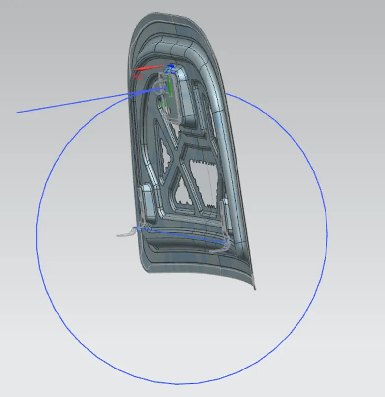
- Now on a plane passing through the centre of this line and perpendicular to it, a circle is drawn to mark the trajectory of the striker.
- A radial line at an angle is created and at the intersection of this line with the circle, a tangent is drawn.
- In the Striker, a line is created at the centre of its locking hook, which is then coincided with the tangent line of the circle. This would ensure that the striker follows the trajectory.
- Further the striker surface is extracted after positioning it near the hinge at the required position using the wave geometry linker feature. This surface is extended using the extend sheet and then made into an emboss using the law extension and the trim and extend feature. The necessary blends are provided. Then, the entire surface is thickened to 0.75mm using the thicken feature.
- Thus, the inner panel design is completed with the hinges and striker poisoning.
- Then the outer panel is created using the parent surface by making offset surfaces and trimming and blending the sheets to get a hem shape. Then it is thickened to 0.75mm. This linked part is called the outer panel.
Trajectory of hood
It refers to the path that the hood follows while opening and closing. For proper opening and closing of the hood, it is required to position the striker, the striker should be perpendicular to the trajectory of the hood.
Views of the designed hood:
Front view:
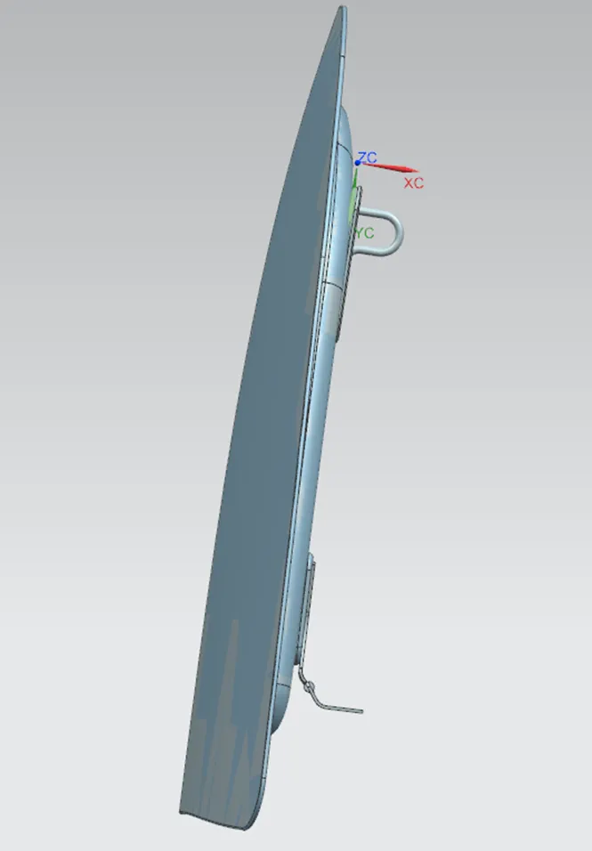
Side view:
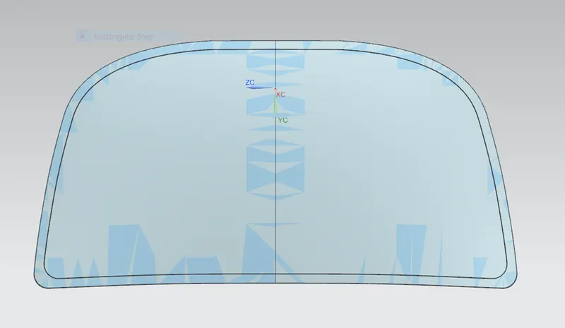
Top view:
Bottom view:
Isometric View
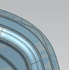
Front Relief
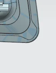
Rear Relief
SHEET METAL OPERATIONS:
- Blanking and piercing
- Deep drawing
- Embossing
- Hemming
Blanking and piercing:
In the blanking, piercing, and shearing process a punch and die are used to modify webs. The tooling and process between the two are the same, only the terminology is different. In blanking the punched-out piece is used and called blank whereas in piercing the punched-out piece is scrap. The process for parts manufacturing simultaneously with both techniques is often termed pierce and blank, an alternative to piercing is punching.
Deep drawing:
Deep drawing is a sheet metal forming process in which a sheet metal blank is radially drawn into a forming die by the mechanical action of a punch. It is thus a shape transformation process with material retention. The process is considered "deep" drawing when the depth of the drawn part exceeds its diameter. This is achieved by redrawing the part through a series of dies. The flange region (sheet metal in the die shoulder area) experiences radial drawing stress and tangential compressive stress due to the material retention property. These compressive stresses (hoop stresses) result in flange wrinkles (wrinkles of the first order). Wrinkles can be prevented by using a blank holder, the function of which is to facilitate controlled material flow into the die radius.
Emboss:
Sheet metal embossing is a stamping process for producing raised or sunken designs or relief in sheet metal. This process can be carried out using matched male and female roller dies, or by passing a sheet or a strip of metal between rolls of the desired pattern. It is often combined with foil stamping to create a shiny, 3D effect.
Joining techniques of inner and outer panel:
- The inner panel and outer panel of the hood should be joined rigidly without disturbing the styling surface of the hood which is the outer panel. Here we use special joining methods known as Hemming and Mastics.
Mastic Data
- The outer panel can't be bolted or welded to the inner panel because of aesthetic requirements. The solution to this problem is mastic sealant and hemming.
- Mastic sealant is an elastic compound that acts as rubber and is placed between the inner and outer panels. Initially, it is in paste form but after the heating process, they will get hardened and joins the inner and outer panel.
- This sealant increases the strength of the panel.
Hemming:
Hemming is a sheet metal forming process in which sheets are joined by bending usually to 180°. Automotive body panels and automotive parts such as deck lids, trunk lids, doors, hoods, and tailgates are formed by the hemming process. Hemming is routinely carried out in aluminum and steel bonnet manufacture.
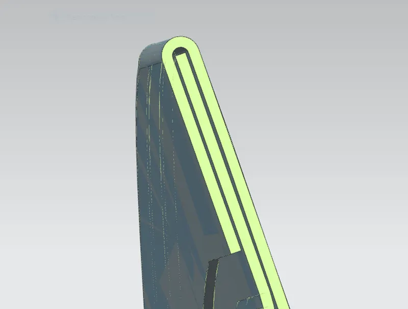
Besides this, the manufacturing of the hood involves various other manufacturing processes like
- stretch forming
- trimming and punching
- deburring
- welding
- grinding
- painting
- baking
- polishing and waxing, and
- Coating.
Conclusion:
- All the components of the hood are designed and assembled using the assembly Section.
- Studied the modelling of the hood from received skin data of Class A surface and its requirements as per Euro NCAP standards.
- Studied the surface modelling techniques and their application to BIW parts using NX-CAD.
- The positioning latch and striker are studied.
- All the necessary Reinforcements were added to the design.
Thus, the Hood is designed that satisfies the manufacturing requirements, and functional requirements as per Euro NCAP standards.