Advanced Sheet Metal Design Using NX Cad Challenge_2_Box Assembly
Project Title - SHEET METAL BOX ASSEMBLY DESIGN
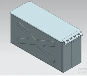
Submitted By – Akhil Raj
Objective
The main objective of the project is to design a sheet metal Box Assembly using NX CAD Software and thereby, understanding and exploring the various tools used in the Sheet Metal workbench of Siemens NX.
Software Used
Siemens NX 12
Introduction
Creating fast, accurate flat patterns is the goal of any organization that manufactures products which contain sheet metal parts. NX Sheet Metal provides a set of tools within the NX design environment that allows for simple and fast design of sheet metal parts, dependent on their material and manufacturing process.
The term sheet metal refers to a piece of metal whose thickness is between 0.15mm and 6.35mm. It is one of the fundamental forms used in metalworking and it can be cut and bent into a variety of shapes.
In NX Modeling, complex uniform thickness parts (often sheet metal) are created either by using surfacing techniques and then thickening the result, or by starting with a solid shape, blending, and then shelling the part to get uniform thickness
With NX Sheet Metal, formed and unformed representations of the parts are created closely following the industry workflows and best practices for bending calculations, tooling, and sheet metal features. The value lies in improving quality and reducing cost of sheet metal parts by producing an accurate sheet metal pattern as the correct input for part manufacture, whether internally or to a supplier. NX delivers the next generation of design, simulation, and manufacturing solutions that enable companies to realize the value of digital twin.
Here we are designing a CAD Model of Sheet Metal Box Assembly using NX CAD software in sheet metal work bench.
Box Assembly - A container with a flat base and sides, typically square or rectangular and having a lid. Box build assembly covers such a wide range of items that it differs each time when required by different people. It can be either as simple as putting items into simple enclosures with interfaces or displays or as complicated as system integrations containing thousands of individual components or sub-assemblies.
Design Methodology Flow chart
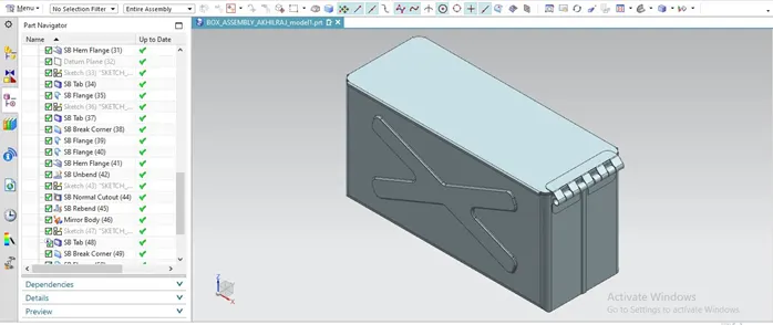
The sheet-metal box assembly designed for this project consists of features like tab, hem flanges, unite, mirror feature, mirror body, closed corner, unbend, rebend, datum plane, cut-outs, bends, flanges, holes, dimples and beads. The design methodology closely follows the industrial procedure to keep the design intent and is summarized in the flowchart below:
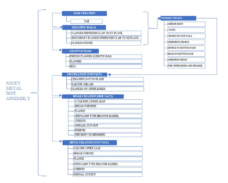
Design Approach
Base creation
A sheet metal tab is created from sketch
Creating walls
- Two flanges are added using the flange command on either side of the tab, perpendicular to XY plane.
- Secondary flanges are created, on the edges of the previous flanges, perpendicular to XZ Plane.
- Used Closed Corner Feature to close the gap between the Tab and the secondary Flanges.
Grooved Seam
A Grooved Seam type of locking is created using pseudo flanges (length 0mm), flanges and hem on the secondary flanges.
Finishing the Box
- The entire body is mirrored about the YZ Plane.
- The parent and mirrored bodies are unified using the unite feature.
- A Dimple is created on one of the walls of the box.
- The dimple is mirrored about XZ Plane using Mirror feature.
- Another dimple is created on the bottom face.
- A bead is created on the bottom face.
- The bead is mirrored across two planes consequently to obtain beads near all four corners.
- The upper edges are hemmed.
Lid Creation (Top face):
- A Datum plane is created at an offset of 203mm from bottom face.
- The Tab for the lid is created using a sketch replicated from top surface of the box.
- The edges of lid are extended using Flange feature.
Hinge Creation (Side face):
- A tab is created on a side wall.
- Using the Break corners feature, the bottom left edge is rounded.
- A flange is created at an angle on the upper edge of the tab.
- Using Open loop type Hem, a circular hem is formed.
- Unbend is used for flattening the hinge body for further procedure.
- A normal cut-out is done to get the required shape for hinges.
- The flange body is brought back to initial shape using the Rebend Feature.
- The body is mirrored to get four hinge barrels.
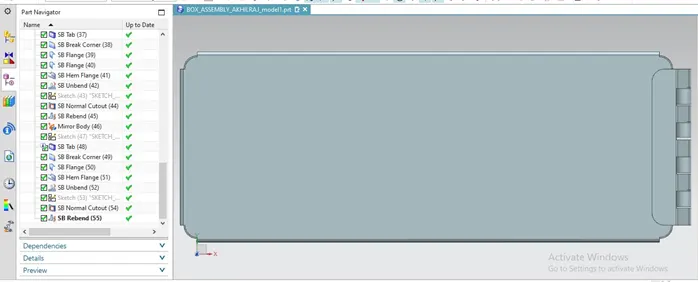
Hinge Creation (Top face):
- Tab for upper leaf of the hinge is created.
- Using Break corners, the top left & right edges are rounded.
- A flange is created at an angle by selecting edge of previously extruded Tab.
- Using the Open loop type Hem, a circular profile is created for the hinge barrels.
- The fold is unbent to obtain a flat profile.
- Normal cut-out is made to get the profile for four barrels.
- Rebend is used to get the initial shape for the hinge.
Description
TAB
Creates a base feature by extruding a sketch along a vector by a thickness value or adds material to a plane face.
FLANGE
Sheet metal flange features consist of a face and bend connected to an existing face along a straight edge. Flange features are added by selecting one or more edges and specifying a set of options that determine the size and position of the material added.
CLOSED CORNER
Closes a corner where two adjacent flanges meet by extending the bends and flanges.
HEM FLANGE
Modifies the model by folding the edge a sheet metal flange over onto itself for the purpose of safe handling or to increase edge stiffness.
MIRROR BODY
Copies a body or mirrors it across a plane.
UNITE
Combines the volume of two or more bodies into a single body.
DIMPLE
Lifts an area of the model inside a sketch that simulates a stamping tool.
MIRROR FEATURE
Copies a feature and mirrors it across a plane.
UNBEND
Flattens a bend and the material adjacent to the bend.
REBEND
Restores an unbend feature to its previous bent state, along with any features added after the unbend feature.
BEAD
Lifts material along the contour of a sketch that simulates a stamping tool.
DATUM PLANE
New plane w.r.t to XY plane of datum coordinate system to an offset of 203 created.
BREAK CORNER
Rounds or chamfers a sharp corner of a tab or flange.
NORMAL CUTOUT
It cuts the model perpendicular to the sketch.
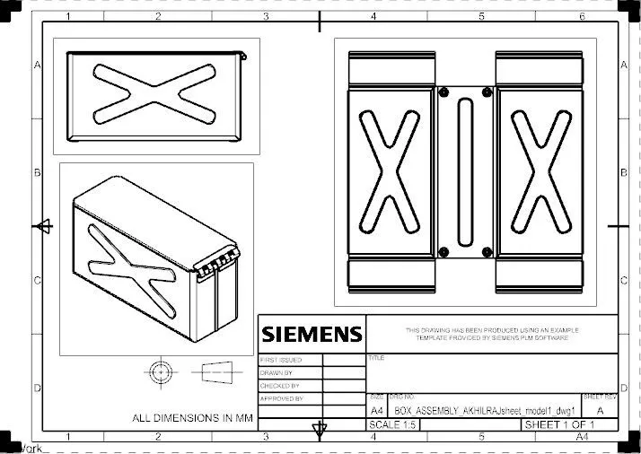
Final CAD Model of Sheet Metal Box Assembly
FRONT VIEW
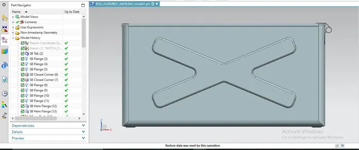
SIDE VIEW
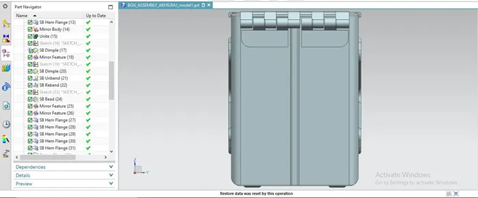
ISOMETRIC VIEW
TOP VIEW
DRAFTING SHEET
Conclusion
- Designed a sheet metal box assembly using NX CAD Software.
- Learnt the design approach and various tools used in the Sheet Metal workbench of Siemens NX.