Advanced Sheet Metal Design Using NX Cad Challenge_5_Odd Shaped Enclosure
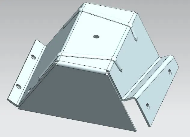
Project Title - DESIGN OF ODD SHAPED SHEET METAL ENCLOSURE USING NX SHEET METAL APPLICATION
Submitted By – Akhil Raj
OBJECTIVE:
To develop a Sheetmetal part in NX sheet metal that contains odd shaped geometry which is not achieved using traditional approach of sheet metal design.
SOFTWARE USED
Siemens NX 12
INTRODUCTION
Creating fast, accurate flat patterns is the goal of any organization that manufactures products which contain sheet metal parts. NX Sheet Metal provides a set of tools within the NX design environment that allows for simple and fast design of sheet metal parts, dependent on their material and manufacturing process.
The term sheet metal refers to a piece of metal whose thickness is between 0.15mm and 6.35mm. It is one of the fundamental forms used in metalworking and it can be cut and bent into a variety of shapes.
In NX Modeling, complex uniform thickness parts (often sheet metal) are created either by using surfacing techniques and then thickening the result, or by starting with a solid shape, blending, and then shelling the part to get uniform thickness
With NX Sheet Metal, formed and unformed representations of the parts are created closely following the industry workflows and best practices for bending calculations, tooling, and sheet metal features. The value lies in improving quality and reducing cost of sheet metal parts by producing an accurate sheet metal pattern as the correct input for part manufacture, whether internally or to a supplier. NX delivers the next generation of design, simulation, and manufacturing solutions that enable companies to realize the value of digital twin.
Here we are designing a CAD Model of an Odd-shaped enclosure using NX CAD software in sheet metal work bench.
In this design challenge, rather than creating a sheet metal tab and then adding features to it,we are using a different approach (i.e., creating a sheet metal object from a solid body and then adding the required featured to form an odd shape enclosure).
DESIGN APPROACH
WORKFLOW
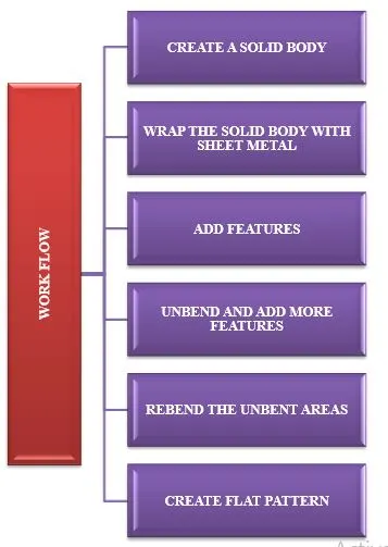
DESIGN METHODOLOGY FLOW CHART
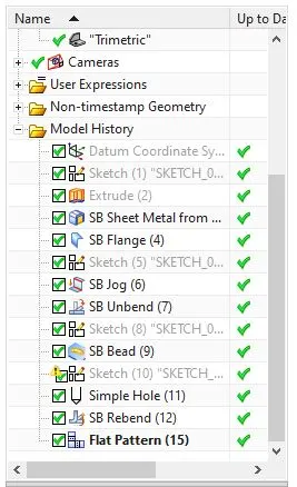
The sheet-metal component was created using commands like extrude, sheet metal from solid, flange, jog, unbend, bead, hole, rebend and flat pattern. The design methodology closely follows the industrial procedure to keep the design intent and is summarized in the flowchart below:
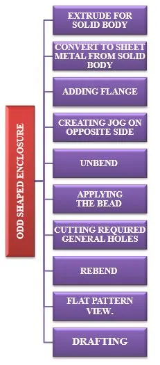
- The required solid body is created using extrude command.
- A sheet metal is derived from the solid using sheet metal from solid command.
- A flange is applied using the flange command.
- On the opposite flange to this secondary flange, using Jog command, a jog of 20mm height is created.
- Using the Unbend feature the job is flattened for further processing.
- Using bead command, the required bead is created on the sheet metal.
- Some 10mm diameter general size holes were cut at different location of job using Hole command.
- Using Rebend command, the sheet metal part is brought back to its initial shape.
- The final step is creating the flat-pattern for the work using Flat pattern command.
FEATURE DESCRIPTION
EXTRUDE
This command creates a solid body by extruding a sketch along a vector by a thickness value or by adding material to a plane face.
SHEET METAL FROM SOLID
This command is used to convert a non-Sheetmetal part to a sheet metal in order to perform the sheet metal operations like unbend, flattening etc.
In NX, solid models and imported non-sheet metal parts could also be converted to sheet metal parts.
FLANGE
Sheet metal flange features consist of a face and bend connected to an existing face along a straight edge. Flange features are added by selecting one or more edges and specifying a set of options that determine the size and position of the material added.
JOG
Jog command is used to create an offset or step in a tab. The small jogs could be used to provide clearance or rigidity to the part. In NX, jog is created by lifting material on one side of the jog line and adding a flange between the two sides.
UNBEND
The Unbend feature flattens a bend and the material adjacent to the bend.
HOLES
Holes are created for fitting purpose. Various type and size of screw holes can be created through this tool. Here some general size hole is created.
BEAD
Lifts material along the contour of a sketch that simulates a stamping tool. Beads can also be created to stiffen sheet metal part.
REBEND
Restores an unbend feature to its previous bent state, along with any features added after the unbend feature.
FLAT PATTERN
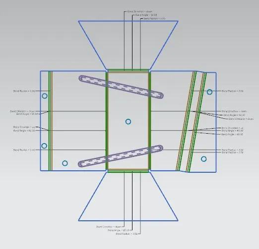
Flat pattern is the representation of the entire sheet metal component in the 2D form of the flat sheet metal with all the bends, cut-outs, holes, and additional features in the form of lines or edges. The flat pattern calculates the material and layout required to flatten a 3D sheet metal model and ensures the ability to cut the sheet metal out of the raw sheet metal plate. It removes the possible errors such as interference or collision within the same component.
DRAFTING
After the design is complete, the execution or the manufacturing of the component requires a technical drawing of the component with the provided scale and with accuracy. The necessary details such as annotations, callouts, bend tables can be added as per the requirement.
DRAWING SHEET
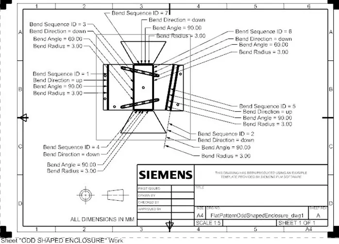
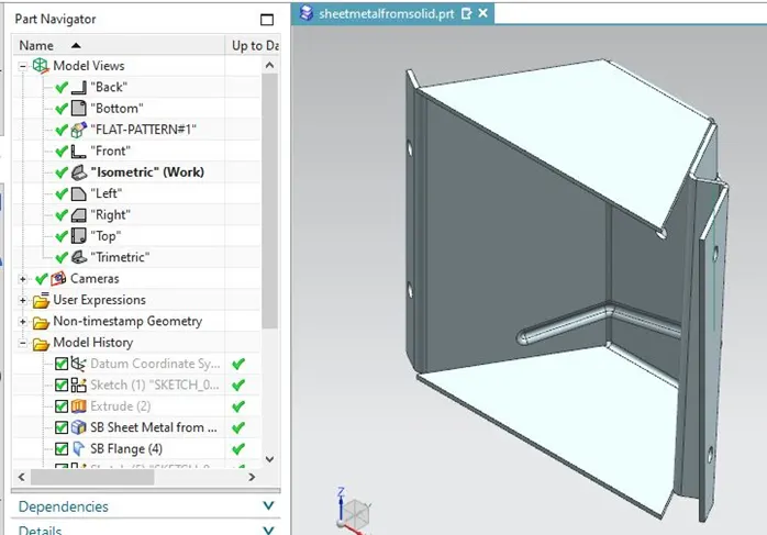
FINAL CAD MODEL
ODD SHAPED ENCLOSURE
(MODEL VIEWS)
Top View
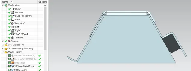
Bottom View
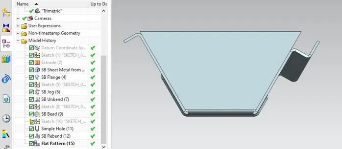
Front View
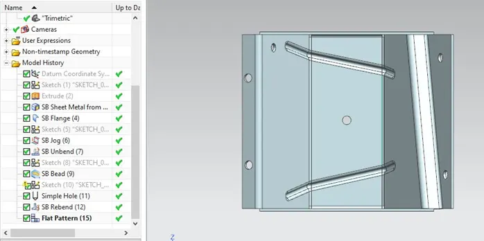
Side View
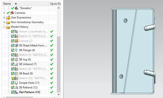
Isometric View
Feature Tree
CONCLUSION:
- Successfully developed a Sheetmetal part in NX sheet metal that contains odd shaped geometry which is not achieved using traditional approach of sheet metal design.
- Studied the work flow and to edit the parameters that are reflected in the flat-pattern like bend-line colour codes, visibility of parameters like bend radius, bend angle etc.
- Learnt the design approach and various tools used in the Sheet Metal workbench of Siemens NX.