Radar Mast & Final Assembly of Yacht
DESIGN OF SUNSEEKER PREDATOR YATCH
Objective
The main objective of this project is to learn and practice the basic tools, commands, and the part modeling of the customized Sunseeker Predator Yacht using Solidworks. The objectives of this project are as follows:
- To design individual parts of the Sunseeker Predator Yacht with surface and solid modeling.
- To assemble the parts modeled individually.
- To set up the camera, lights, scene for the environment setup and to apply the appearances and decals on their respective parts.
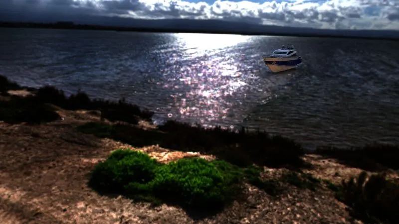
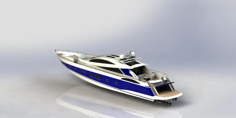
- To create a rendering of the assembled model and create a photo-realistic image using Solidworks Visualize and photo-view 360.
Introduction
Sunseeker is a British brand that has evolved over the last 51 years. The Sunseeker Predator Yacht principle is to provide luxury and comfort with high speed in timeless elegance. The hull structure of the Sunseeker Predator Yacht is designed in narrow shapes that provide high speed to the yacht. This is the detailed report describing the design of a model of the yatch with individual parts-modeling and further assembling using Solidworks. Once the parts get designed and assembled, the rendering and visualization will be performed to visualize the model as a photo-realistic image using Solidworks Visualize and Photoview 360.
Design Methodology
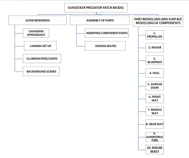
Part Modeling
Parts which are to be assembled to give a 3D prototype model are initially modelled separately by sketching and using some features.
Features are the individual shapes that, when combined, make up the part.
The parts of Part Modeling can be created from a conceptual sketch through solid features based on modeling, building and modifying parts through direct and intuitive graphical manipulation.
The part modeling can be obtained on the 3D modeling software which is Solidworks. This report consists of features, parts, tools, assembly, visualization and steps to complete the design of the Sunseeker Predator Yacht.
Surface Modeling
Surface modeling is based on the external aspects of the model.
Surface Modeling gives the ability to build out the visual representation of the exterior of an object and its contouring.
It is a kind of the boundary of the model which can be converted into solid for a later purpose.
Surface modeling plays a major role in modeling the yacht. Most of the parts in the yacht are surface model.
Features Description
- The sketch is a 2D tool to select the plane, make the outlines of the model, assign the dimensions as the part required. The sketch is an initial step for the part modeling which gives the overview reference about the model.
- Extrude Boss/Bass is the most common 3D tool used to provide the 3D environment to the 2D sketch. It provides the desired length and dimensions in the 3D model from which it can be transformed into desired shapes and sizes for the part by using other 3D tools.
- The fillet is available in both 2D sketch features and 3D tool features. Both features are used to provide roundness to the corners and edges of the part. The fillet tool trims out the intersection corner and brings the tangent relation to the fillet arc.
- Dome is the 3D feature that allows providing roundness to the surface of a particular face. It is available in elliptical and circular functions.
- Offset is available in the 2D sketch which offsets the sketch to the assigned distance with a reverse function to make it in the desired direction. Also, it is available in 3D surface tool in which it offsets the faces or edges to the desired distance and direction.
- Lofts can be a bass/boss, cut, and surface modeling. It is an important 3D tool that can be obtained by a transition between two profiles with the reference of the guide curve.
- Extrude Cut is the 3D tool feature that is used to remove the section as per the area defined by the 2D sketch. It also behaves as an extrude which builds the sketch in a 3D model, but it removes the section as per the sketch similar to extrude.
- Revolve is focused on 3D tool Features in which, the sketch completes a dimensional cycle around a reference axis at the desired angle. The angle can be modified according to the model dimension.
- The split brings the existing part into multiple parts with its 3D tool features function. With this feature, it can split solid bodies as well as surface bodies. To split a surface, the Trimming Surface must extend past the boundaries of the surface to split.
- The chamfer is the 3D tool feature that is used to remove the sharp edge of the model. The removal of a sharp edge means to make a sloping edge. It can be brought by two methods that are –
- Distance-Angle Method - in which distance and the angle of the slope will be defined.
- Distance-Distance Method- in which the two distances will be defined.
- The combine is to merge two bodies when the bodies have a common area to get merged. It is a 3D tool feature used to make two bodies into one body. It can be added only within one multibody part file.
- The shell can be performed in two ways:
- By selecting a face that creates a hollow body that leaves the selected face open and creates a thin-walled surface as a boundary to the remaining face.
- Without selecting any body, creating the closed hollow solid body with the desired thickness. The thickness can be modified accordingly.
- Dynamic Mirror is the tool from which the sketch gets auto mirrored with the reference of the plane or any selected axis. The axis can be made by the construction line in the sketch tool. The sketch follows up another side of the axis or plane and constructs the sketch on another side as well. Due to this tool, it doesn’t require a mirror tool to make mirrored of the sketch as later on the process.
- Appearance is to assign the environment to the model like assigning the color. The assigning of the environment means to provide the Realtime material to the model like fabric, metal, non-metal, glass, rubber, etc. These are the environment sets that are used to assign to the model.
- Trim Entities is the 2D tool that is used to delete the extra sketch which is coming outward of the intersection. If the point is on the sketch then the entities will get deleted from that point, which means if there is any intersection on the line itself then the extra portion will get deleted with the help of trim entities tool.
- Surface Extend is to extend the surface from its end which was created earlier for the modification to meet the requirement. It is the surface 3D tool that is used to extend the surface by assigning the value as the need to match the requirement.
- Swept Surface is a 3D surface tool used to create a 3D model along with the profile sketch with guide curves, which forms a surface along with the profile sketch. It also contains the guide curve option for making the surface along the guided curve which means the profile will follow the guide curve to form a shape or surface.
- Circular/Linear Pattern is to provide the model as well as the sketch, a circular pattern or linear pattern. The pattern is meant to make a copy of the model or sketch without repeating for the same along the linear (horizontal or vertical direction) or circular (rotates along angle) path.
- Surface Knit is used to combine the bodies. It is a surface 3D tool that is used to fill the gaps between surfaces or make the surfaces get combined. The surfaces which were created earlier don’t need to be on the same plane but it is necessary to be adjacent to each other without being overlapped.
The parts of Sunseeker Predator Yacht Model:
The following are the parts contained in the Sunseeker Predator Yacht to get overall designed:
- Propeller
- Radar
- BluePrint
- Hull
- Garage Door
- Front Seat
- Middle Seat
- Rear Seat
- Super-Structure
- Radar Mast
Description of the features used and parts modelled for the Sunseeker Predator Yacht Model:
- Propeller: The Propeller is used to provide a linear motion by applying thrust over any working fluid which includes water as well as air. The rotation of the propeller along a shaft is used to transmit the linear thrust energy to bring the vehicle in motion.
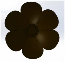
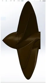
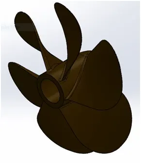
Features used:
- Sketching Profile
- Revolving the sketch
- Using loft
- Extrude-cut the profile
- Filleting the edges
- Using Circular pattern, and
- Applying Appearance.
- Radar: The Radar is mounted over the ship to detect the other ships or yacht to its nearby for the safety purpose of the yacht. The radar is used to transmit the signals to disclose the location on sea or ocean routes to avoid the collision.
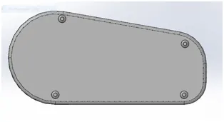
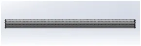
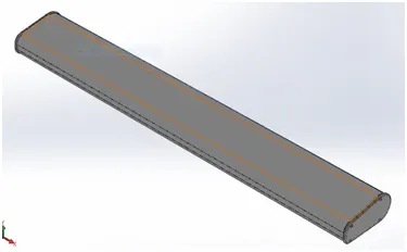
Features used:
- Sketching Profile
- Extrude boss the model
- Extrude-cut the model
- Filleting the edges
- Splitting the model
- Applying sketch driven pattern
- Mirror, and
- Applying Appearance.
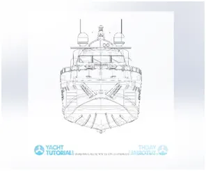
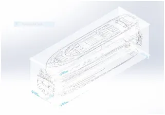
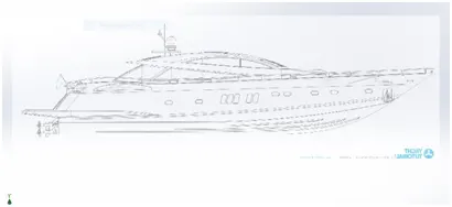
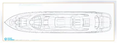
- Blueprints: The Blueprint is the initial step to bring the idea for creating a 3D model. The blueprint consists of different views such as side view, top view, bottom view, front view, and back view. When all these views get adjusted or arranged then the 3D modeling takes place for the final result.
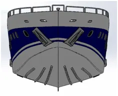
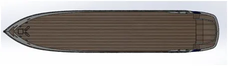
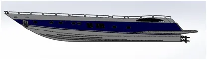
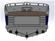
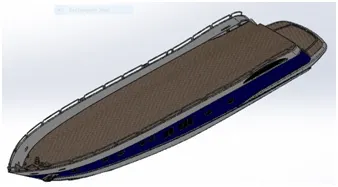
- Hull: The Hull is the major part of the yacht that also works as a carrier that carries the superstructure, seats, jacuzzi, etc on its deck. The narrow design of the hull provides high speed to the yacht. The hull is the only part having contact with the water and keeps motion with the propeller functions.
Features used:
- Sketching Profile
- Projecting the curves
- Sweep the surface
- Using loft
- Using Surface Extrude
- Extending the surface
- Using Surface Knit
- Extrude boss the model
- Extrude-cut the model
- Pattern used
- Using Mirror
- Shell the section
- Split the entities
- Filleting the edges, and
- Applying Appearance.
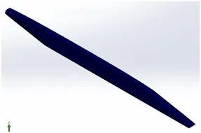
- Garage Door: A garage door is used to cover the empty basement section of the hull which is used to store a heavy vehicle or transport the automobile safely from one place to another. The door can be used for various purposes like to cover the empty section or to provide a better look rather than an open section.
Features used:
- Sketching Profile
- Shell the section
- Extrude-cut the model
- Taking reference plane
- Filleting the edges
- Mirroring the model
- Applying Appearance.
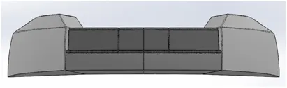
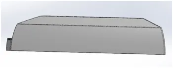
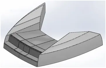
- Front Seat: The Front Seat is mounted over the front deck of the hull which is designed uniquely considering the space over the deck of the hull in the front. The design of the front seat is covering most of the space of the deck because of its unique design like the wing which amazes the look of the yacht.
Features used:
- Sketching Profile
- Surface Trimming tool
- Surface extrusion tool
- Surface knitting
- Sweep surface
- Extrude-cut the model
- Filleting the edges
- Chamfering the edges
- Revolve boss the sketch
- Applying Appearance.
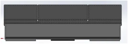
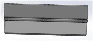
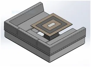
- Middle Seat: The Middle Seat is mounted just behind the superstructure model of the yacht, nearby the entrance door of the superstructure over the deck of the hull. The middle seat is designed with the central table which is surrounded by three-sided seats.
Features used:
- Sketching Profile
- Extrude-boss the model
- Taking reference plane
- Filleting the edges
- Extrude-cut the model
- Chamfering the edges
- Mirroring the model
- Applying Appearance.
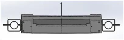
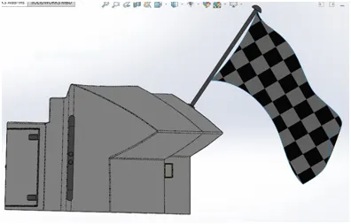
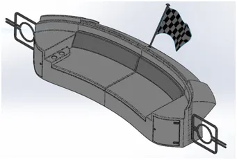
- Rear Seat: The Rear Seat is mounted over the rear deck of the hull just above the garage. The rear seat is designed according to the rounded shape of the rear deck, having cup holders and drawers. A flag is also designed over the seat on its backside. The rear seat also carries the gates to block the stairs.
Features used:
- Sketching Profile
- Extrude-boss the model
- Taking reference plane
- Filleting the edges
- Extrude-cut the model
- Chamfering the edges
- Mirroring the model
- Using Revolve-Boss
- Applying Dome on the handles
- Applying Appearance
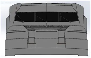
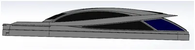
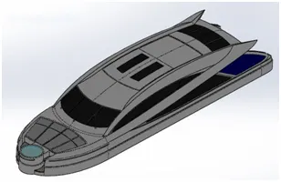
- Super-Structure: The Super-Structure is the bulk design of the yacht which is covering the largest space of the deck of the hull. It is mounted over the hull with a Jacuzzi amenity with itself. The design of the super-structure is complex with lots of curves but the curvy designs provide an impressive look to the yacht.
Features used:
- Sketching Profile
- Projecting the curves
- Sweep the surface
- Using Surface loft
- Surface Trimming tool
- Extending the surface
- Using Surface Knit
- Using Surface Extrude
- Using surface fill
- Extrude boss the model
- Extrude-cut the model
- Delete face used
- Using Mirror
- Taking reference plane
- Ruled surface used
- Shell the section
- Split the entities
- Filleting the edges, and
- Applying Appearance
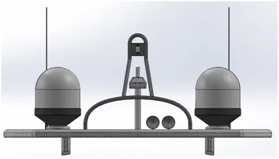
- Radar-Mast: The Radar-Mast is the topmost portion of the yacht which is used for carrying the antenna as well as the horn.
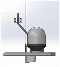
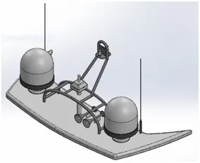
Features used:
- Sketching Profile
- Projecting the curves
- Swept boss
- Using Revolve-Boss
- Applying Dome
- Surface Trimming tool
- Using Surface Extrude
- Extrude boss the model
- Using Mirror
- Taking reference plane
- Shell the section
- Filleting the edges, and
- Applying Appearance
The Assembly of Sunseeker Predator Yacht
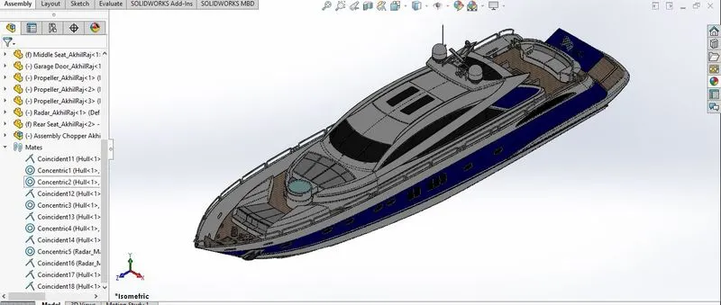
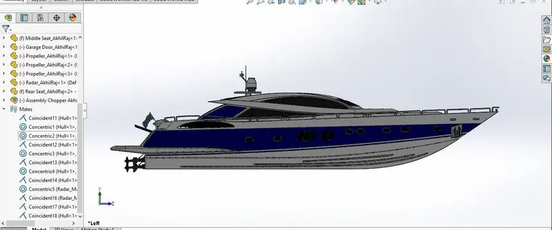
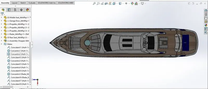
The parts of the Sunseeker Predator Yacht were imported individually and assembled by giving proper mates like parallel, perpendicular, concentric, coincide, etc.
Some of the parts were automatically positioned with correct constraint relations because of the pre-imported surface while designing the part.
NOTE : A pre-modelled Assembly of an American Chopper was placed in the Garrage Area. The parts like Radar, Propeller, Garrage door and the Front Fork of the chopper are not fully constrained because they are moving parts and were needed to be moved to suitable positions to give a realistic appearance while rendering.
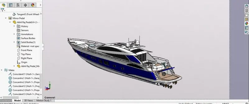
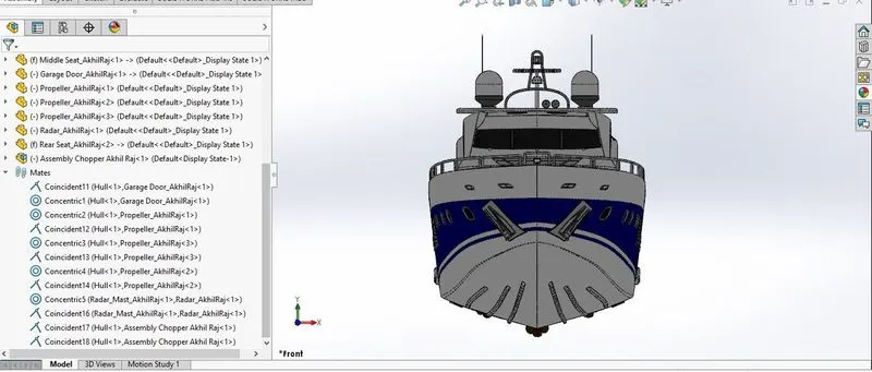
Features used:
- Inserting the parts using an “Insert Part” feature
- Mating the inserted part on their respective position using the “Mate” feature.
Visualization or Rendering:
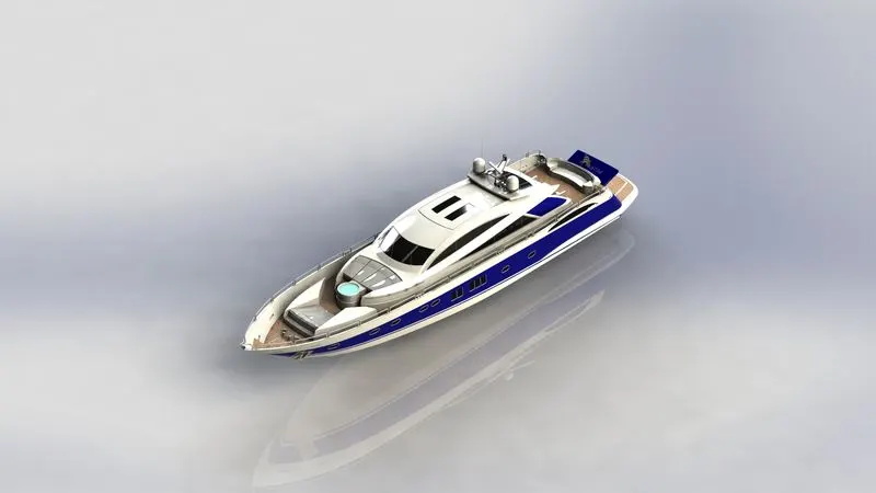
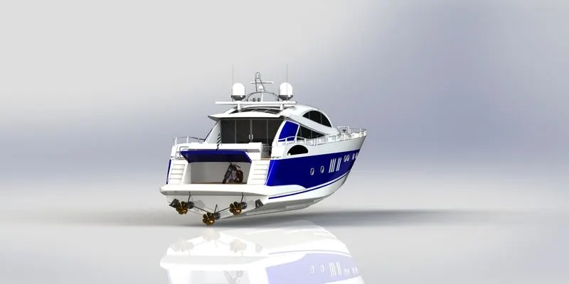
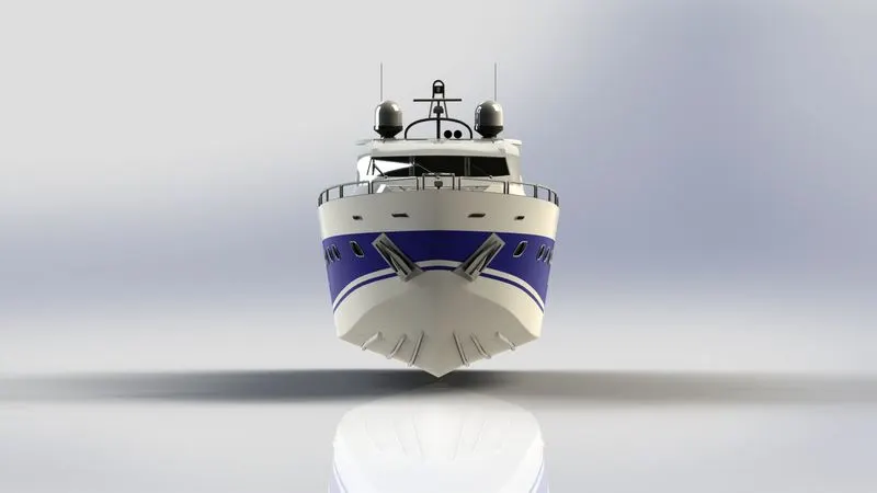
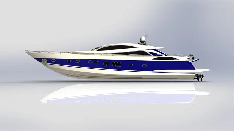
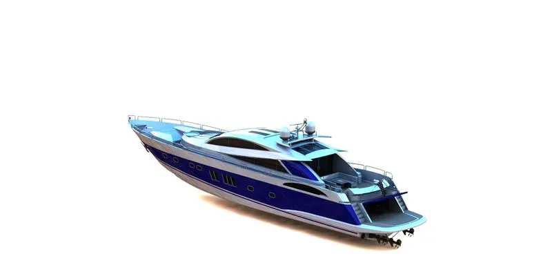
- Rendering is the process of creating realistic images of the photorealistic model with the environment.
- Rendering is done in two ways in solid works. The following are the two ways,
- Photo view 360
- Solid-works Visualize
3.In the photo-realistic model, the camera, lighting and scenes were set before the final rendering.
4.Then the photo-realistic model is rendered into realistic images with different views.
5.Here I have used the photo-view 360 for rendering the assembled model (I preferred the Visualiser because of the various background setups available but my resources were not sufficient for rendering such a complex assembly in the Visualiser).
Conclusion:
The Sunseeker Predator Yacht project was assigned to understand the tools and 3D features of the Solidworks with proper functioning. The following objectives were fulfiled:
- Modelled the individual parts of the Sunseeker Predator Yacht with surface and solid modeling.
- Assembled the parts modeled individually.
- The camera, lights, scene for the environment setup as well as the appearances and decals on their respective parts were given.
- The rendering of the assembled model was done using Solidworks photo-view 360.
I thank my mentor Mr. Soundar Rajan Sir, for patiently guiding me to overcome the challenges that I faced in this project.