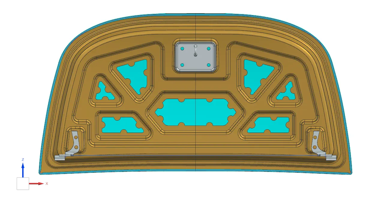
Hood design-Week 2
Hood Assembly using NX CAD:
Hood:
It is the front covering of the car and it has the front engine in it. It is also known as bonnet.
It protects the engine from external particles and gives easy access if we need to make repairs.
It also dissipates the heat formed in the engine and helps it come out of the engine compartment instead of staying in the car.
A hood consists of carious components:
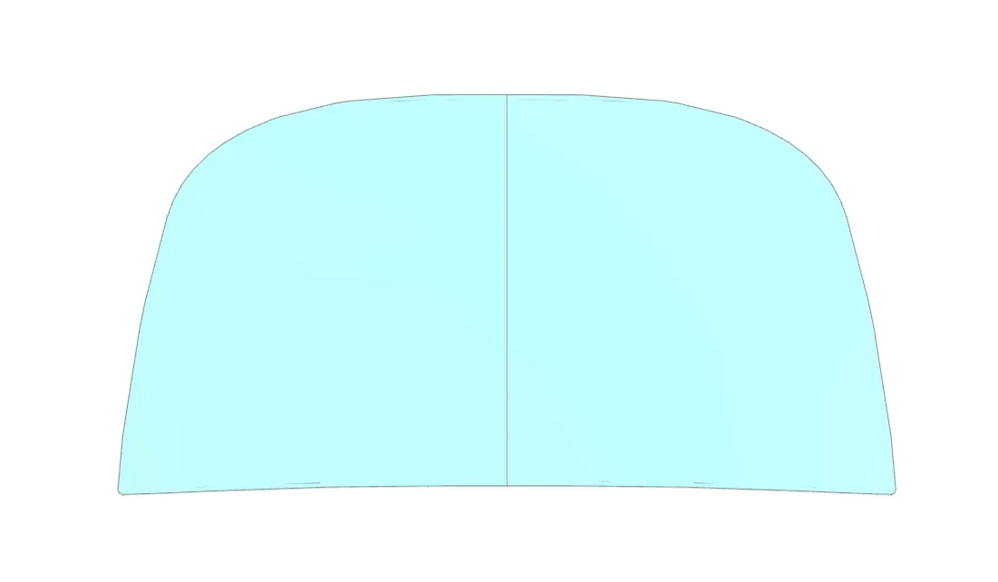
1. Hood outer panel: This is the outer part of the hood assembly. It works as a metal cover.
2. Hood inner panel: This is the inner part of the hood assembly. It provides strength to the hood. It has several embosses to increase structural rigidity. Having these embosses also helps to ensure proper force distribution. It also helps to save material.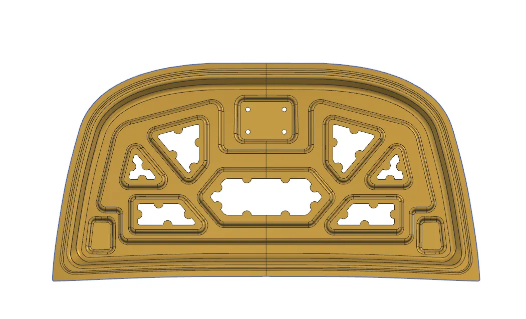
Between the hood outer and inner panel, there is a stiffener pad. This is made of sponge and it helps to prevent noise and vibration.
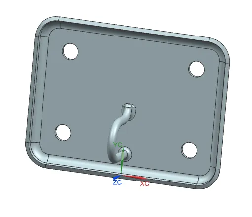
3. Striker: Hood striker consists of the latch that helps to secure the hood and prevent it from moving. Striker is placed on the hood inner panel. In the area where the striker is placed, the strength decreases. So in those regions we add additional material. This is known as striker reinforcements.
4. Hood stay: Hood stay is a component that helps us to keep the hood of the car in open position when the engine needs maintenance or repair work. Hood stay is of two types:
a. Support rod: It is a long rod that is used as a hood stay. It is used when the hood is light enough to be manually lifted. It is not straight and is typically bent or curved. This is done to prevent wobbling. Support rod should always be away from the battery when the hood is in open position to prevent interference. The start and end points of a support rod in open position are called hood retaining point and body side retaining point.
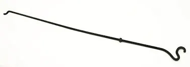
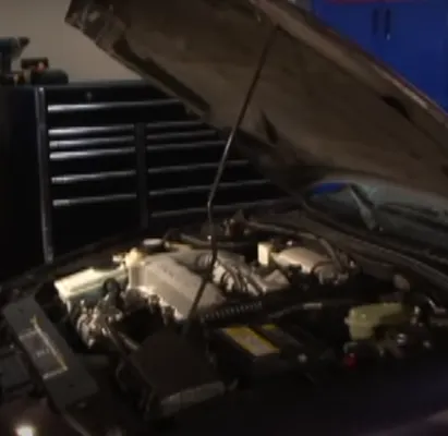
The bends in the support rod should be less than 35mm.
b. Gas stay: Gas stay supports are filled with a gas, such as nitrogen, to create pressure needed to keep the hood open. This does not require much manual power and is used when the hood is heavy. The gas stay is fixed using a stud ball. When a gas stay is used, we add an extra bracket which helps to add weight. This is called a reinforcement.

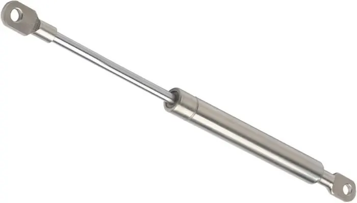
The gas stay requires less human power as it is automatic, while the support rod needs more human effort. But on the other hand, the gas stay is more expensive while support rod is much cheaper. So based on the pricing range of the car, the decision between support rod and gas stay is made.
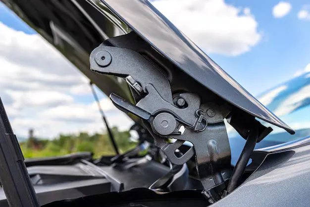
5. Hinge: It is a mechanism that allows a hood to open and close. Similar to striker, the hinge mechanism is reinforced as well.
Latch trajectory:
It is the path followed by the striker when the hood is opened or closed about the hinge axis. The trajectory of the latch is taken as a circle with the center of the hinge axis taken as the center of the circle. The striker is to be mounted in such a way that the normal drawn through the center of the striker is a tangent to the circle or the latch trajectory.
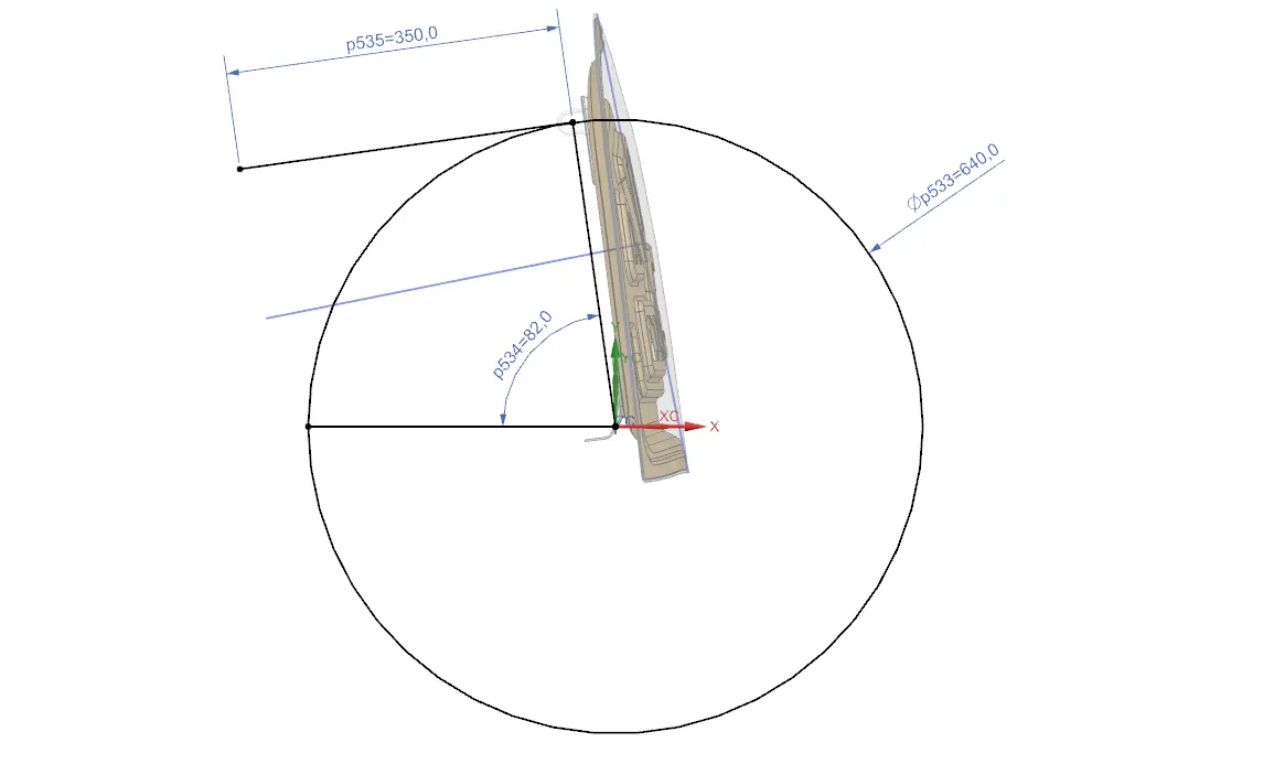
This perpendicularity is important because it endures that the striker latches smoothly.
Mastic data:
Mastic sealant is used to fill gaps and create bonds between surfaces. It is used to join the inner and outer panels of the hood. It helps to reduce the noise, vibrations and harshness. It is a flexible and elastic substance that is applied on points of the hood known as the mastic points. Mastic sealants have an effect for 80mm around them.
Mastic sealant is applied as a paste on mastic points and are then put in a furnace and heated to harden. this joins the hood inner and outer panels.
Embosses:
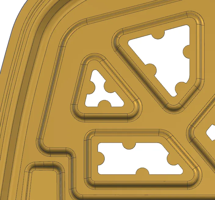
These are provided in order to increase the structural rigidity of the hood. They help to dissipate the force of impact during collision away from the passenger cabin and towards the hinges.
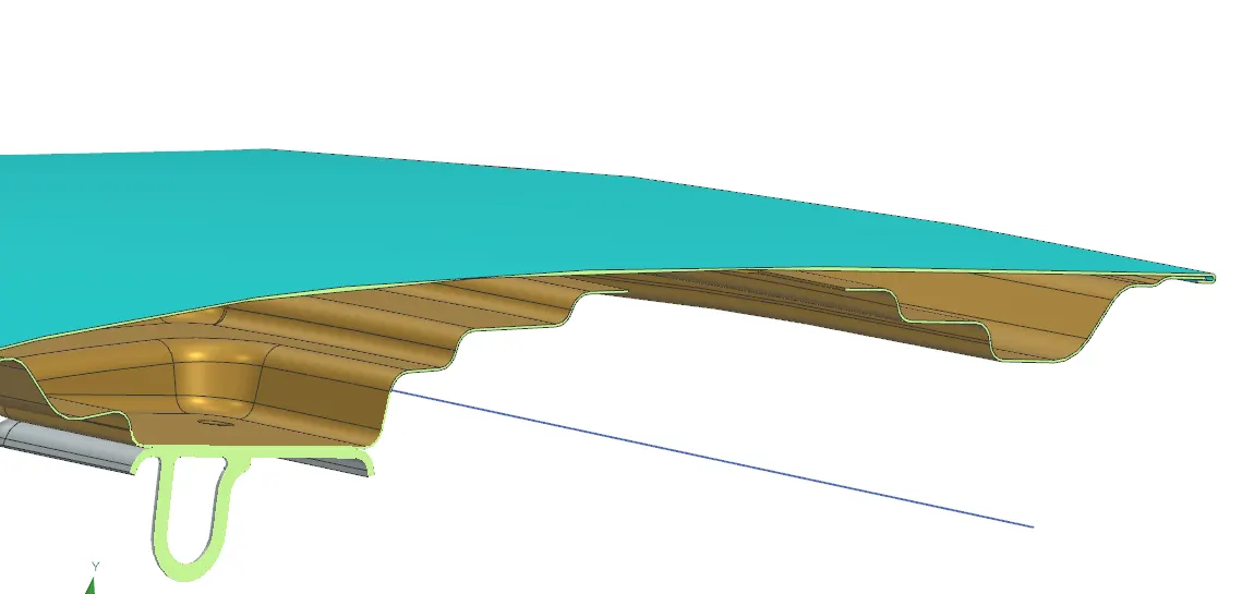
Embosses also help to provide greater strength even though thinner sheet material is used. This helps to reduce costs and also reduces the weight of the car. This in turn increases the efficiency of the car. Embosses are also provided with cutouts. these cutouts also help to reduce the amount of material used and the weight of the car.
Deep drawing:
It is a sheet metal forming process that uses a punch to create a deep part from a flat sheet metal. It is considered to be "deep drawing" when the depth is greater that the diameter of the part.
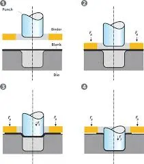
It can be used to create complex curved surfaces with great accuracy. It is a cost effective alternative to "turning" process/ The strength of the deep part is greater that that of the sheet metal.
A die is placed under the sheet metal in the shape of the desired part. Then a punch is used to push the sheet metal into the die giving it the shape of the die.
Hemming:
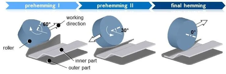
Hemming is an assembly process that is used in hood design when compact joints are required and when the aesthetic of the edges needs to be very high.
In "Hood hemming" process, the outer panel extends beyond the inner panel and it is bent 180 degrees under the inner panel. This assembles the two together.
There are rollers at different corners. The rollers bend the hood outer onto the hood inner and provide finishing. There are multiple rollers because one roller cannot cover the whole good. Each roller turns 2-3 times to ensure proper hemming.
If the force applied by the rollers to too high, it causes vibrations which in turn leads to deformities. To prevent this, CAE team performs several simulations to find the right amount of force.
This force needs to be high enough for hemming to take place but not too high that it causes deformities.
Hood assembly using NX CAD:
1. Create an assembly and name it "Hood Assembly" and save it into a new folder. Then add component and insert the hood outer panel and fix it.
2. Now create a new component in hood assembly and name it Hood inner panel. Make sure that the same location is given for all the components of the assembly.
3. Using WAVE geometry linker, extract hood outer panel into the Hood inner panel. Now trim the component with the central datum plane. After trimming, break the link between the outer panel and the extract in Hood inner panel. Then the trim sheet command in hood outer panel can be deleted.
4. Now to create tooling axis, join the two points on the ends of the trimmed outer panel and create another line bisecting this initial line.
5. The flanges need to be created. Activate hood inner panel and offset the surface by 1.7mm as per the master section. Then offset the boundary using "offset curve in face" tool by 20mm. Trim the offset with the curve and the first flange is obtained.
6. Repeat this process to get the second and the third flange as well. Between each flange, "through curves" tool is used to join them together. Then blends are to be given to all sharp edges.
7. Now draw a sketch to construct the first emboss. Make sure provision is given for both the striker and the hinge assembly. A clearance of 5-10mm is necessary to prevent stress concentration. The sketches must be fully constrained.
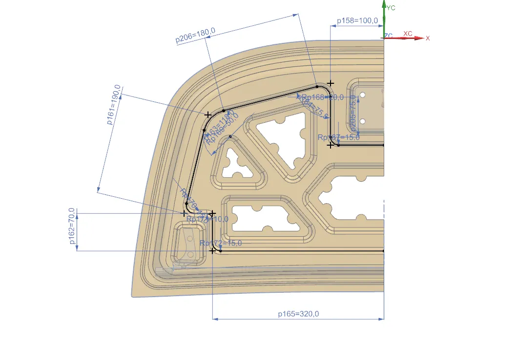
8. Project the curve onto the hood inner panel and use "Emboss" tool to give an emboss of 10mm at a draft angle of 10 degrees with the tooling axis. Then give "Blend" of radius 6mm to the emboss edges.
9. Now smaller embosses are created within this large emboss. These can either be created in the same sketch or in separate sketches.
10. Through calculations, the depth of the smaller embosses will be around 8.5mm. Also the draft angle needs to be increased to 12 degrees.
11. Now cutouts are created inside the embosses while making sure there is provision for mastic points. Create sketches inside each emboss and project the curves and trim the sheet with the projected curves.
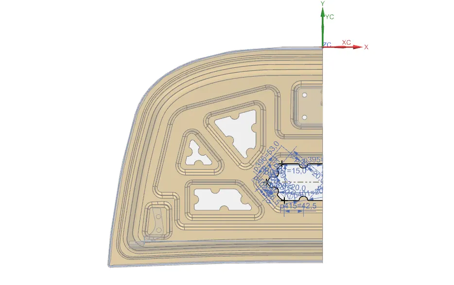
12. Now create reinforcement for the hinge. This can be any shape like a polygon or an oval as long as the hinge has enough support.
13. We use sketch tool to create the shape of the reinforcement and then use emboss tool to create the reinforcement.
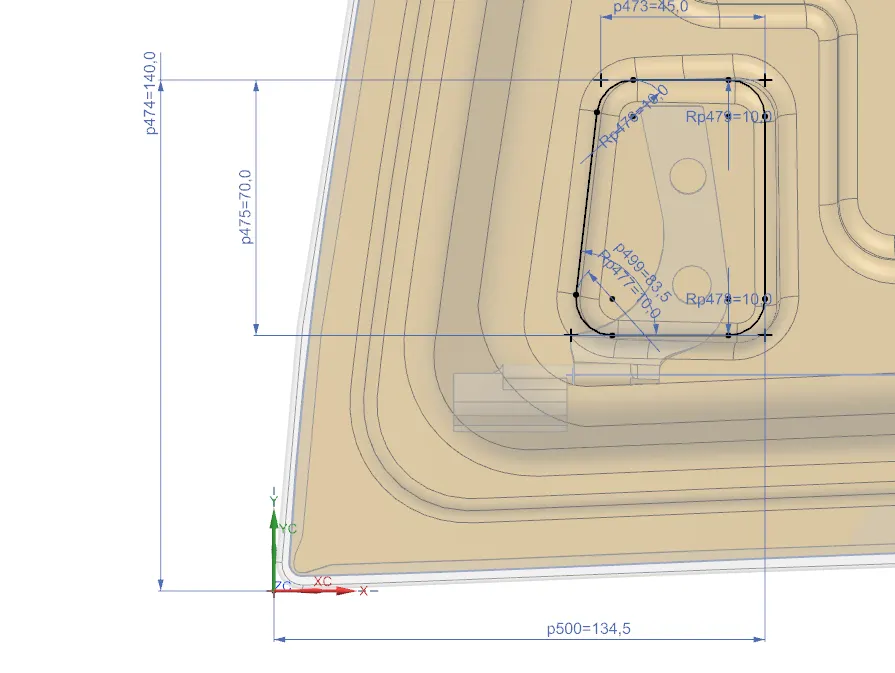
14. Using assembly constraints, mount the hinge onto the hinge mount.
15. Now insert an associative copy by using "mirror geometry" tool with respect to the YZ central datum plane. Then make sure there are no gaps between the inner panel and the mirror geometry and sew the two surfaces together.
16. Now to construct the striker mount, create the latch trajectory over the hinge axis and create a tangent at an angle such that it is close to the striker position.
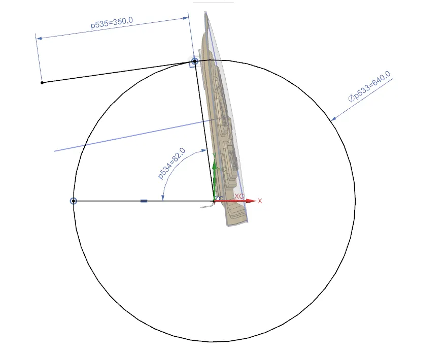
17. Create a normal passing through the middle of the striker latch and create a datum plane at the center of the striker.
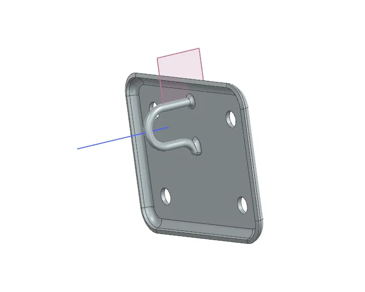
18. Using assembly constraints, align the striker to the hood in the correct position and manipulate the angle such that there is enough space for the mount to be created.
19. Using WAVE geometry linker, extract the base of the striker and use extend tool to extend it by 7mm to ensure there is enough space for the striker to be mounted after blends are provided to the mount.
20. Use law extension tool to extend it beyond the hood inner panel and provide a draft of 12mm. Use "trim and extend" tool to trim it with the hood inner panel. Provide blends to the mount.
21. Manipulate the angle between the two radii to control the height of the striker mount. Thicken the inner panel by 0.75mm using "Thicken" command.
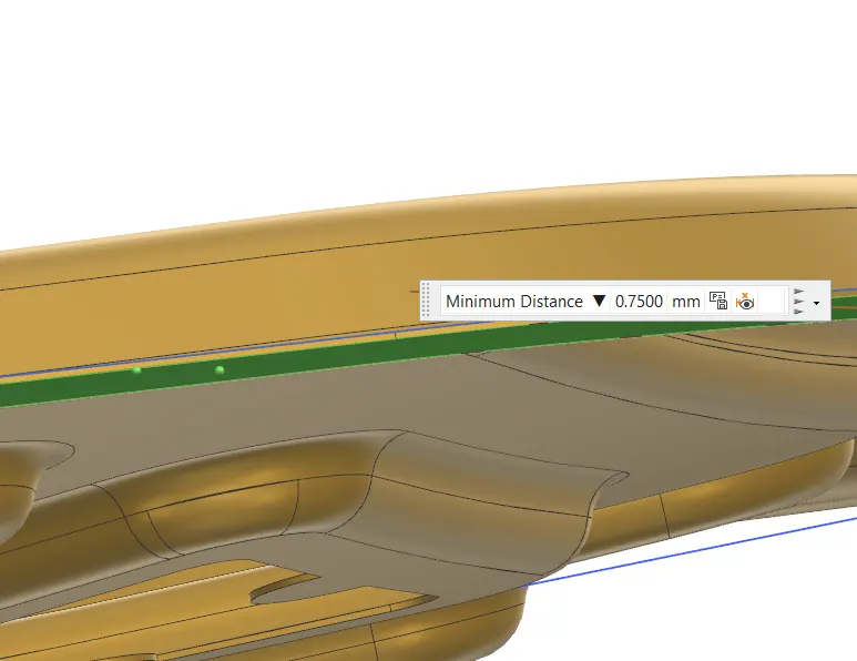
22. The sharp corners of the inner panel need to be rounded by using bridge curve tool on both sides.
23. Now activate hood outer panel and trim it down the middle to make it easier to work with. The inner and outer panels need to be assembled using hemming process.
24. Offset the outer panel by 2.65mm. Then offset the boundary by using "offset curve in face" tool. This offset value needs to be 20mm. Trim the offset with the curve.
25. Offset the same boundary by 0.1mm. Create a law extension between the boundary of the offset surface and the new 0.1mm offset curve.
26. Use "three face blend" tool to blend the three surfaces together. Now hem reliefs need to be provided. This can be done by using curve on surface tool in spline mode.
27. Create the spline in such a way that there is a clearance of at least 3mm. Then trim the outer panel with it.
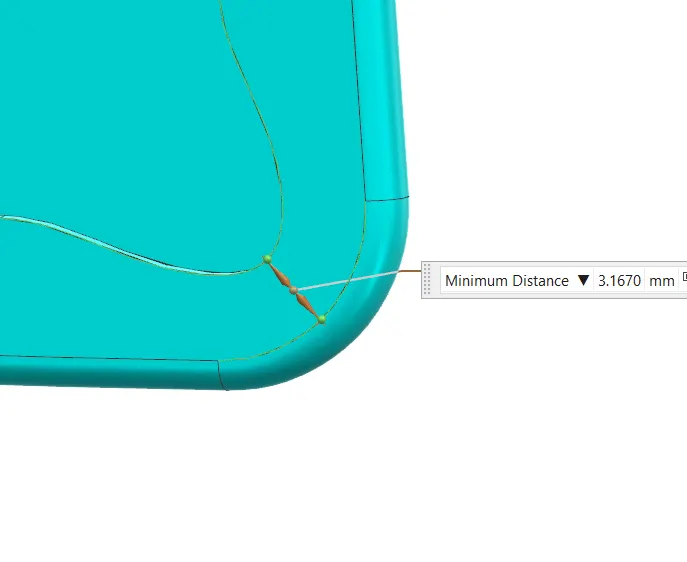
28. Use mirror geometry tool to obtain the other half of the outer panel and sew both halves together. Use thicken tool to thicken the outer panel by 0.75mm.
29. Unhide all components and activate the hood assembly. Using clip section view and measure tool, make sure there is adequate clearance between the inner panel and the end of the outer panel. It has to be at least 2mm.