Hood design-Week 2
AIM: To design Hood Outer Panel, Inner Panel and the necessary reinforcements by following the Master Section mentioned with the Design parameters that is explained in the videos.
OBJECTIVES: To design the Hood Assembly in NX-CAD or NX 12 with the help of detailed explanation about hood and its components, Latch Trajectory, Mastic Data, Emboss Definitions, Manufacturing process like Deep-Drawing and Hemming, and all the parameters given in the design as shown above. The parts and assembly are saved in .prt file ass well as .srt file. All the steps regarding the emboss, hemming, assembly constraints, etc. are followed to achieve the final output.
DESCRIPTIONS:
Hood: The hood or bonnet is the hinged cover over the engine of motor vehicles. Hoods can open to allow access to the engine compartment or trunk on rear-engine and some mid-engine vehicles for maintenance and repair.
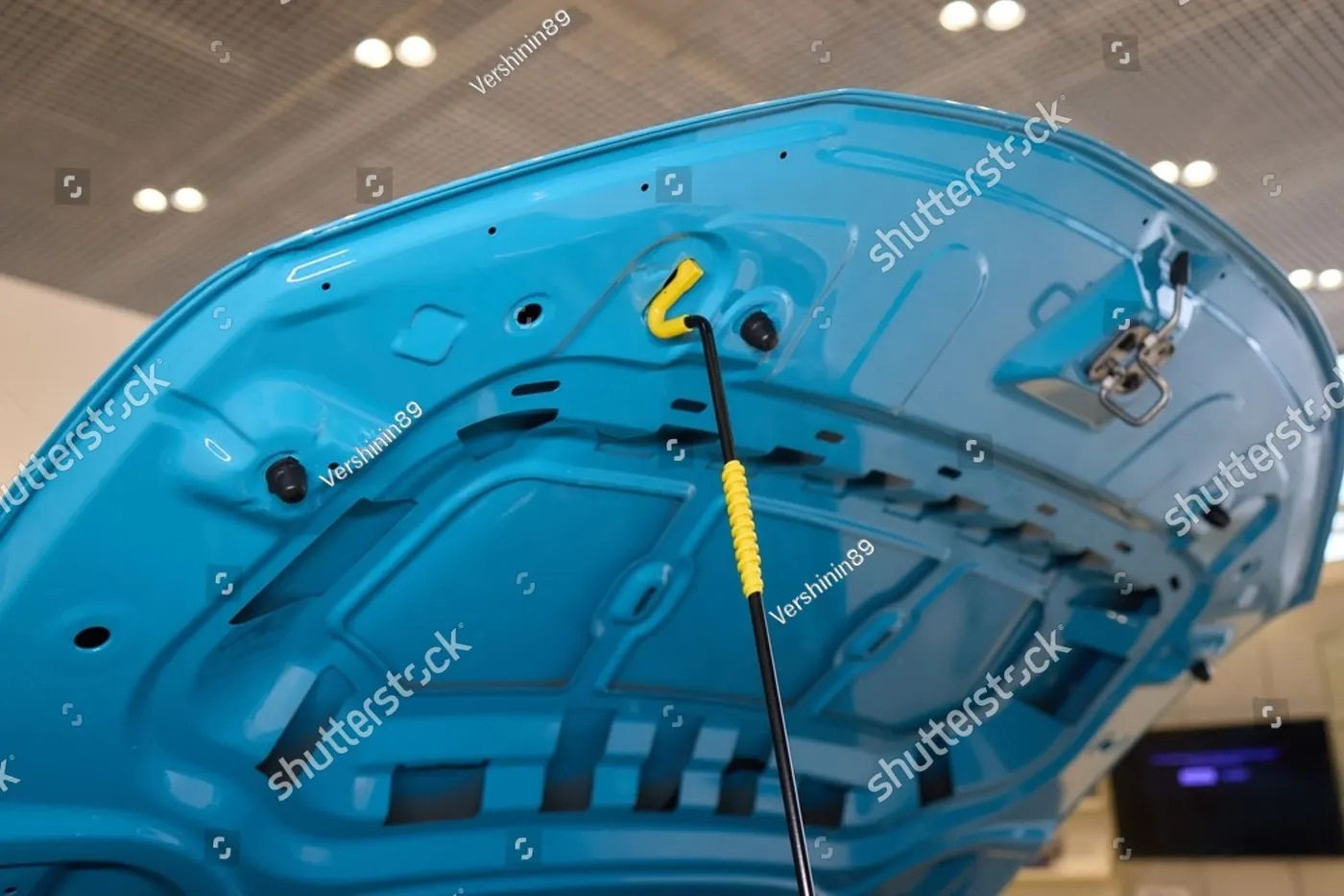
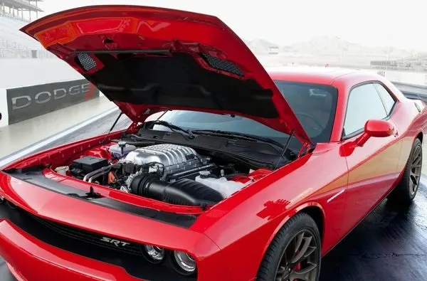
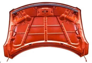
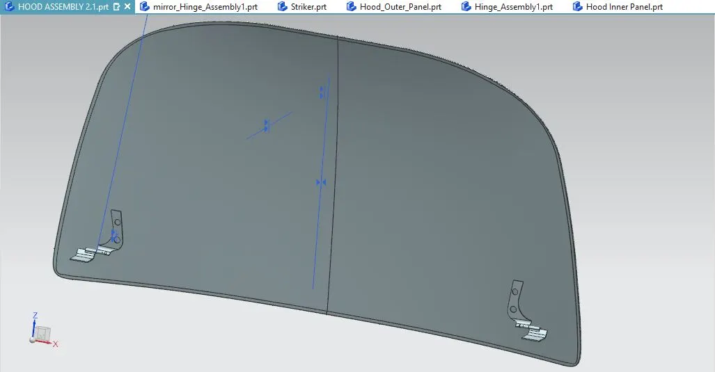
Hood Assembly: The assembly part consist of Hood Inner and Outer panel that is hemmed together and also fitted with Hinge Assembly and a Stricker mounted. The hood of a car is considered as the frontal BIW enclosure component. Bonnets are designed to reduce air resistance as the air flows around the car. Apart from this, bonnets are also designed to meet several other requirements. They serve a great deal of purpose in protecting the passengers inside the car & the pedestrians in the event of an accident. It also acts as the cover for the engine.
Hood Inner Panel: The inner panel is an object of the present invention to provide a hood inner panel capable of reduction of a reaction force of the hood inner panel even if a level of deformation of a hood of a vehicle increases, and ensuring a sufficient energy absorption capacity.
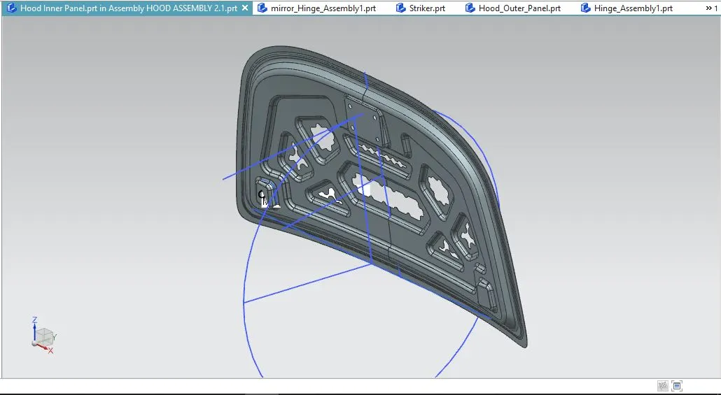
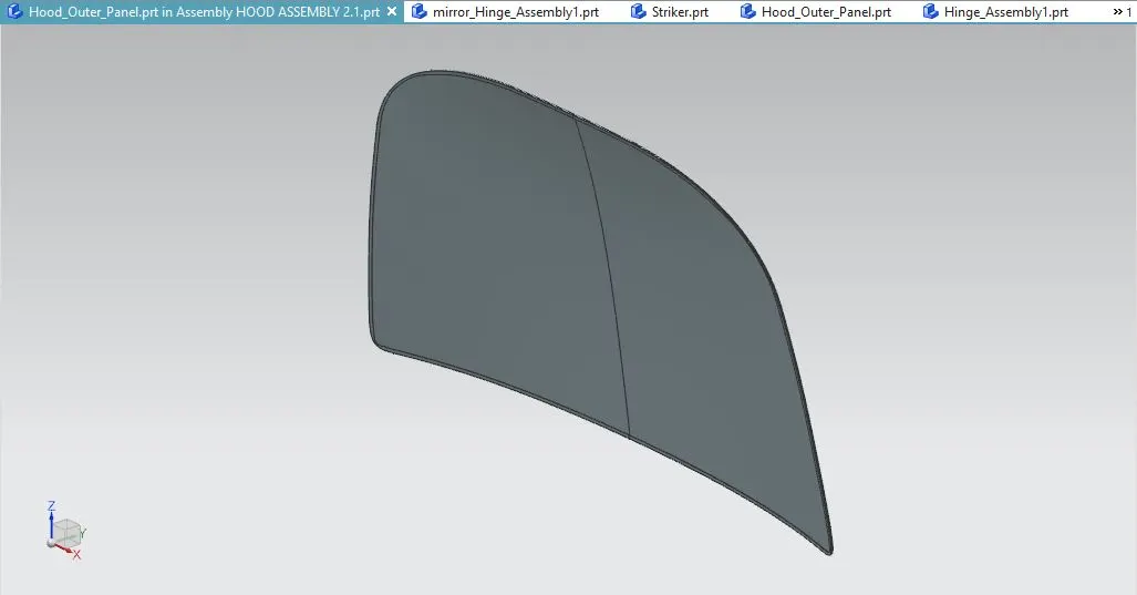
Hood Outer Panel: Also known as cover of inner panel. It is the part, which gives luxurious look to the hood or bonnet. Outer & inner panel can not join by any welding process like spot welding or rivet, which spoil the outer look of a car. The outer panel is generally extracted model from the prototype design.
Hinge Assembly: Hinge Assembly is a component that fixes the hood to the fenders of the car. The latch must be fixed perpendicular to the hinge axis so that the hood opens or closes properly.
Striker: A Latch & striker is used for locking the hood with the car. It is usually placed on the space provided on the inner panel. It is strategically placed above the upper emboss of the Hood Inner Panel with exact constrains.
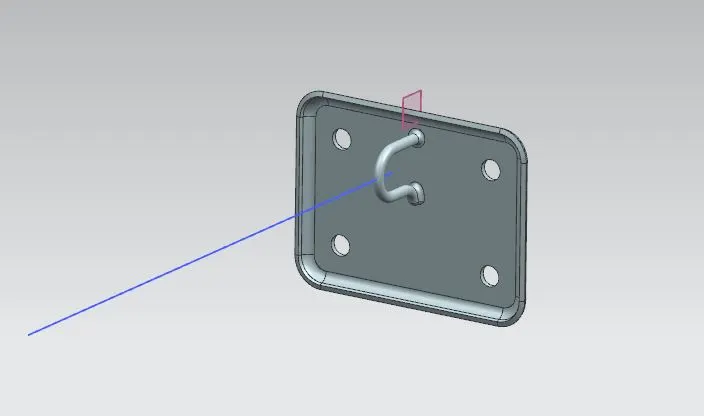
Latch trajectory: While opening or closing the hood, the latch must be accurately aligned to the fixing or striker point. For that, the latches trajectory must be perpendicular to the hinge axis.
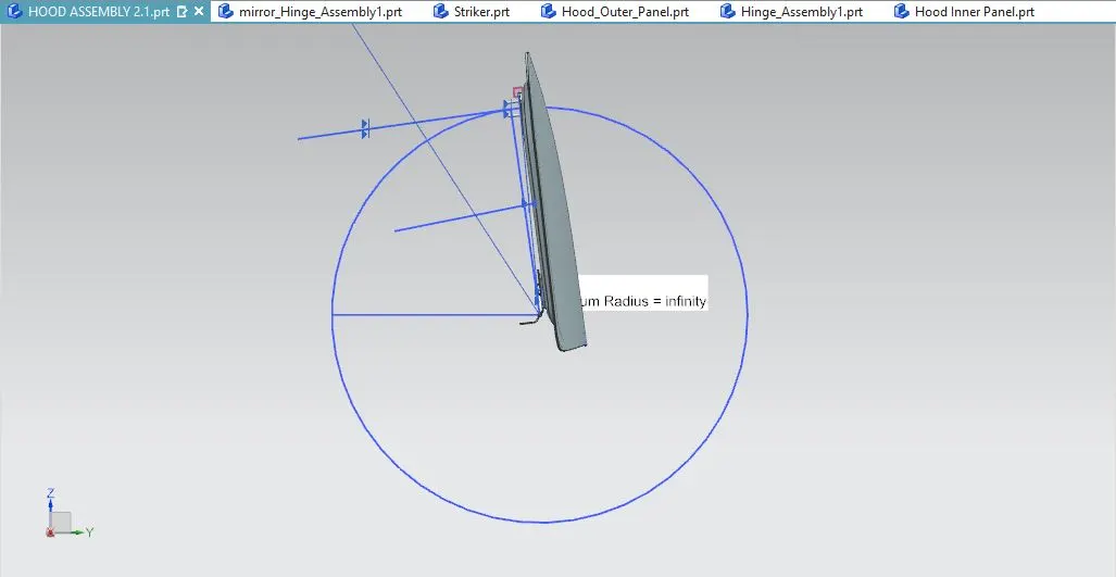
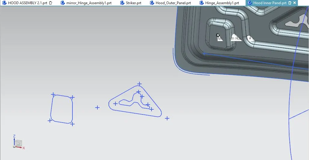
Mastic Data: MASTIC DATA: Mastics are the sealant applied between hood's outer panel (which is styling surface) and hood's inner panel. The black circles in the figure above are the regions where mastic sealants are applied.
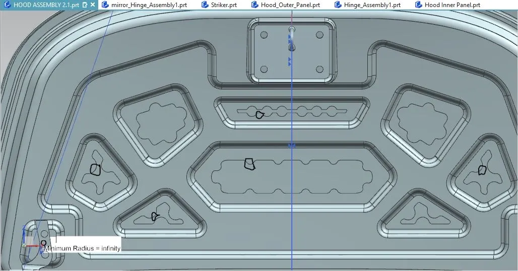
Emboss Operation: The sheet metal embossing operation is commonly accomplished with a combination of heat & pressure on the sheet metal, depending on what type of embossing is required. A sheet metal is drawn through the male & female roller dies, producing a pattern or design on the sheet metal. Depending on the roller dies being used, different patterns can be produced on the sheet metal.
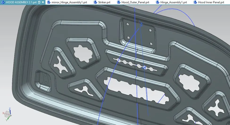
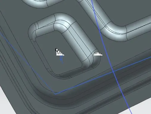
Deep Drawing: Deep drawing is a manufacturing process that is used extensively in the forming of sheet metal into a cup or conical box-like structures. Pots & pans for cooking, containers, sinks, automobile parts, such as panel & gas tanks, are among a few of the items manufactured by sheet metal deep drawing. A deep drawing of sheet metal is performed with a punch and die. The punch is the desired shape of the base of the part, once drawn. The die cavity matches the punch and is a little wider to allow for its passage, as well as clearance. For many calculations, the sheet metal thickness is assumed to remain constant. There are changes in thickness in certain areas, due to force involved.
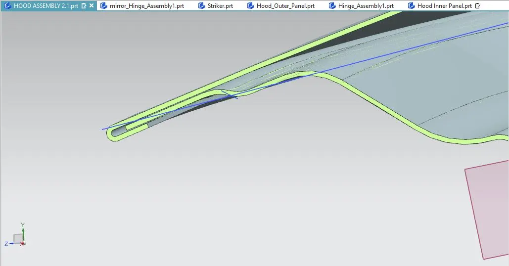
Hemming: Hemming is a sheet metal forming process in which sheets are joined by bending it usually to 180 degrees. Automotive body panels & parts such as deck-lids, trunk-lids, doors, hoods & tailgates are formed by hemming processes. Roll hemming is carried out incrementally with a hemming roller. An industrial robot guides the hemming roller & forms the flange. Roll hemming operation can also be divided into several pre-hemming & final hemming process steps. Conventional die hemming is suitable for mass production. In die hemming, the flange is folded over the entire length with a hemming tool. Normally the actual hemming is a result of a forming operation in which the flange is formed with a hemming tool after the drawing & trimming operations have been completed.
PROCEDURES:
1) Open NX 12
2) Go to Files -> Open -> Select the part -> OK
3) Open all the parts one by one to proceed to to the assembly operation.
4) Go to Files -> New -> Name it as 'HOOD ASSEMBLY 2.1'-> OK
5) Go to Home -> Add -> Open ->Select 'Hood Inner Panel' -> OK -> Give the fix constraints to it.
6) Do the same with 'Hood Outer Panel' without giving the fix constraints to it.
7) With the Wave Geometry Linker, select the surface of the 'Hood Outer Panel' in the inner panel part. Break the link by un-ticking the 'Associative'.
8) Finish the design of the inner panel given in the descriptions above with given design processes.
9) After creating all the embosses, law extensions, edge blends, etc. the surface is being thickened in upward direction to get the final design of the inner panel.
12) The Hinge Assembly along with it's mirror part is then fitted with the inner panel emboss surface in the assembly part.
13) The trajectory of the Hood is drawn along with its tangent to match with the center line of the latch of the Striker to join the striker on the inner panel.
14) Create the emboss of the striker on the inner panel of the with wave geometry linker and law extension.
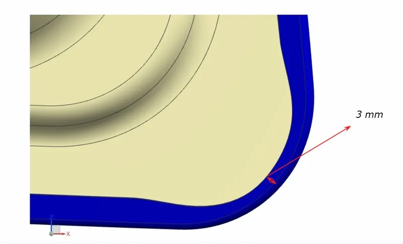
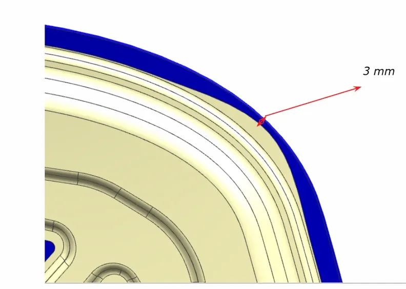
15) For the Outer Panel, with the help of offset surface, offset curve, trim, etc. we get the hemmed to get the final surface. The part is then finally thickened in downward direction.
16) Then after making assembly part as a work part, the entire final hood is then saved in Save All command in both .prt and .srt file.
OUTPUT:
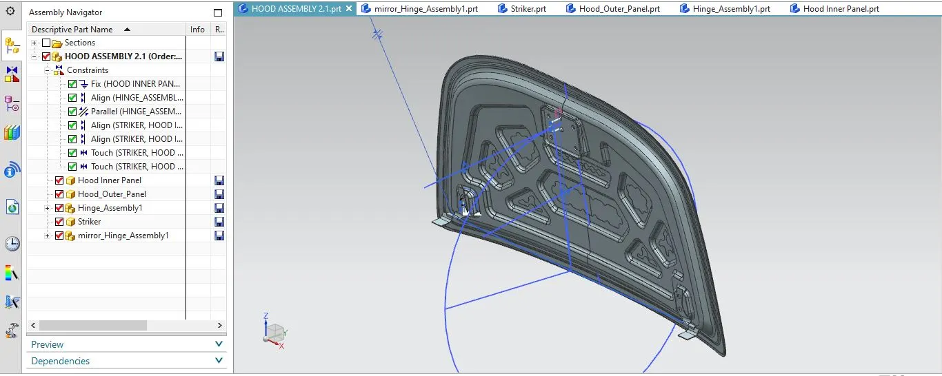
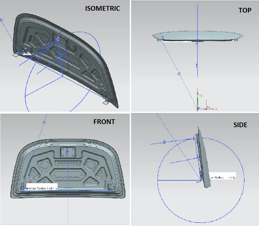
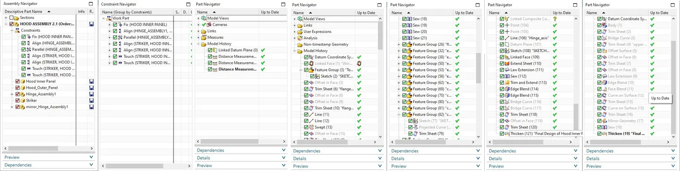
The outputs are given below in the form of screenshots of .prt as instructed above in the question for the completed model from Hood design-Week 2:
a) 3D views:
b) Navigators Tree Structure:
INFERENCE:
The design was achieved through the tooling axis and inner and outer panel surfaces and doing the necessary operations to get the final output as shown above. Next the thickening surface was solidified through 'Closed Surface' command. After that all the .prt's along with it's .srt's parts were attached below and the entire report is submitted.
NOTE: Due to the attachment being < 20MB, the .zip file couldn't be attached below. So the drive link is given below the answer part through link
https://drive.google.com/file/d/1nTa5ogyH3QXjQhLvJE-jJRpmjNbtGgYV/view?usp=sharing