Hood design-Week 2
CAR HOOD DESIGN USING NX
Introduction:
Hood is an thin hinged sheet that covers and protects the car's major components, such as the engine, power train, drive belts, battery, lamp unit. Its major purpose is to direct access to the car's critical components for repair and maintenance, as well as to protect these components from direct sunlight and dust. It's essentially a reinforced skin panel with a many of safety and quality specifications. The most significant factors are occupant and pedestrian safety. A well constructed hood will ensure their safety.
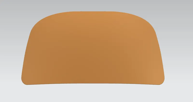
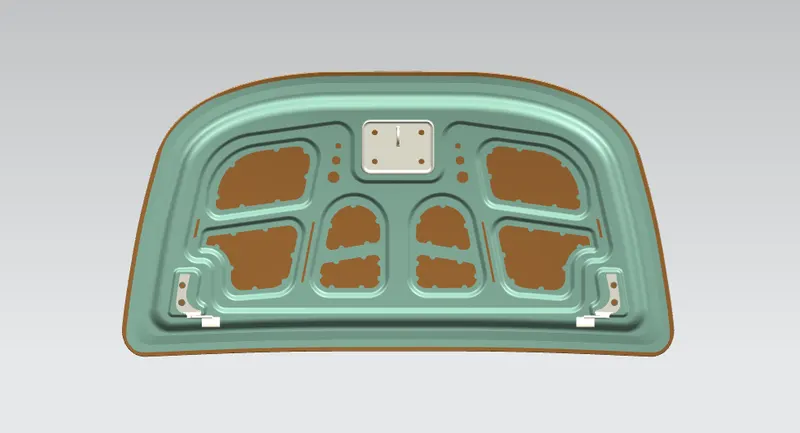
A hood is typically made of 4 important parts
- Outer panel
- Inner panel
- Latch and striker
- Hinge
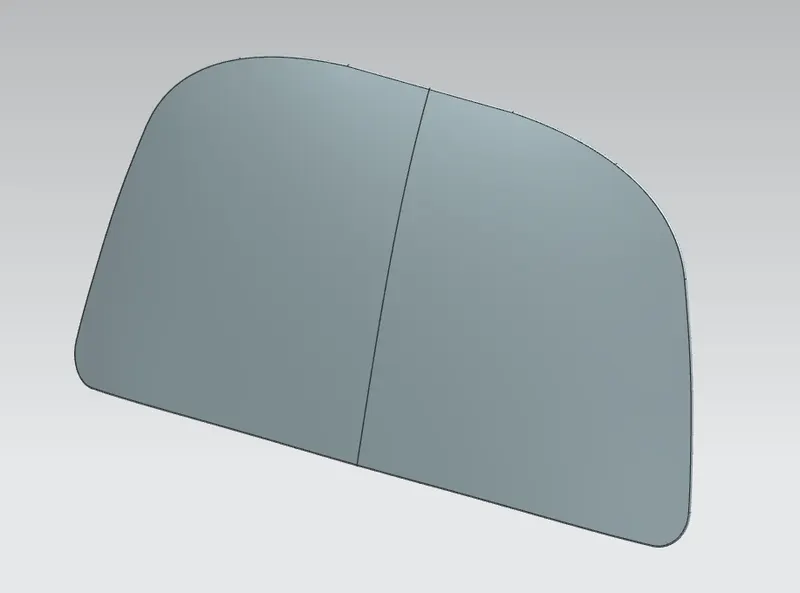
Hood Outer Panel: It gives good looks and provide a secure mounting and covering for vehicle's components, as well as protection for occupants from the elements and during collisions.
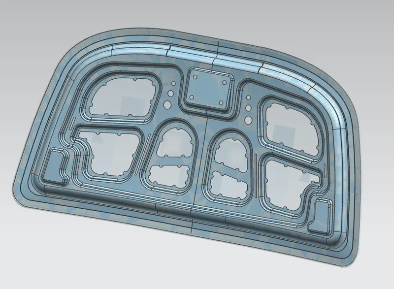
Inner Panel: The emboss with striker and hing mount are included in this component.
Latch and striker: The latch striker purpose is to ensure a tight ftbetween the door and the cab's seal. The striker plate is constructed of hardened metal to avoid wear when the door is opened and closed frequently during the day.
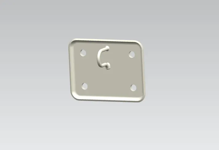
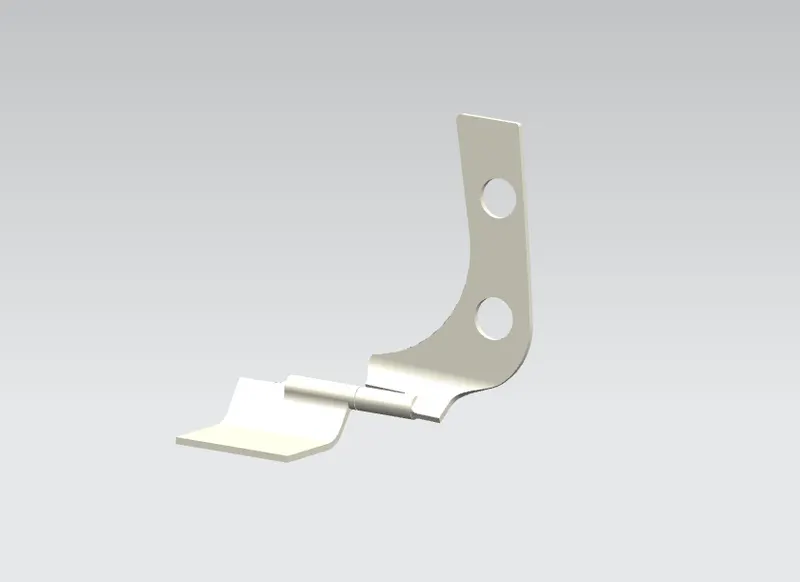
Hinge: Hinges connect two elements while allowing them to rotate in relation to each other.
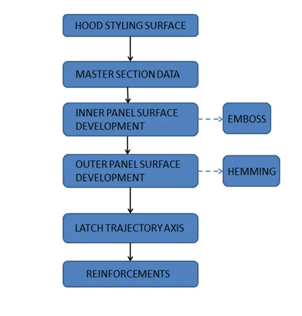
Design Methodology: The following chat depicts the project's objectives.
Data Given:
- Outer Panel Thickness = 0.75mm
- Inner Panel Thickness = 0.75mm
- Reinforcement Thickness = 1.5mm
- Master sketch: It is the styling department's reference section from which the inner and outer panels are built.
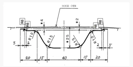
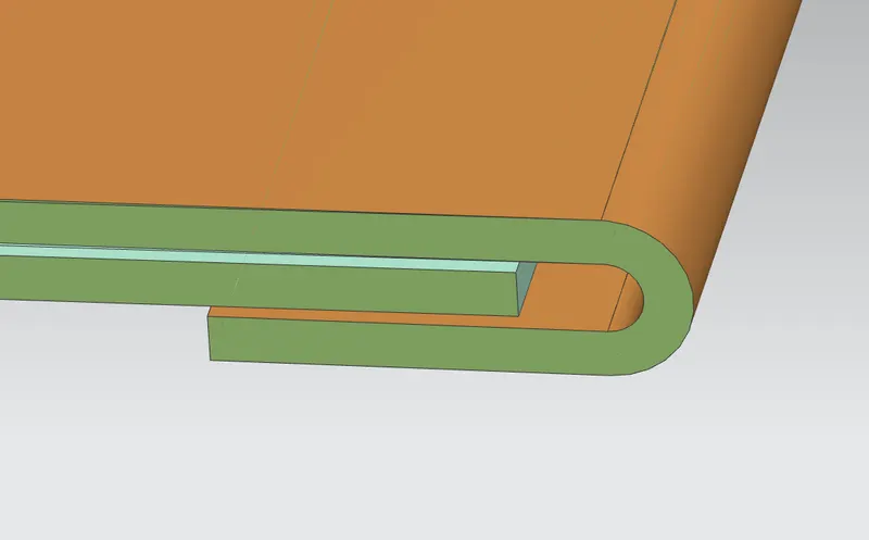
- Hemming Data: The process of bending/folding the outer panel's flange over the inner panel.
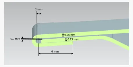
- Relief rear and front section: This eliminates the overlapping sections and relieves stress.
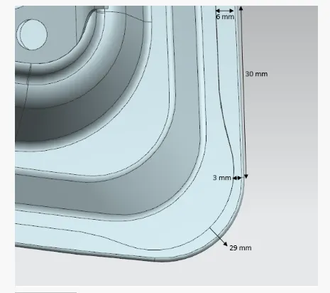
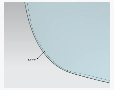
Step 1: File extracted
- First, the suface's neutral data file was extracted.
- Then two work surfaces were established and designated individually as hood inner panel and outer panel by retaining it as a parent file.
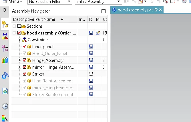
- After that, a new assembly was formed in assembly navigator, and the parts and sub-assemblies were added to it.
- The hing assembly and latch will be constrained once the inner and outer panels have been created.
Step 2: Creating Inner Panel
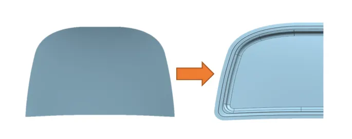
- In this project inner panel is created with the help of styling surface provided.
- We design an inner panel with flanges by offsetting the outer panel for the dimensions specified in the master section.
Step 3: Creating Required Embosses In Inner Panel
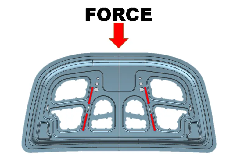
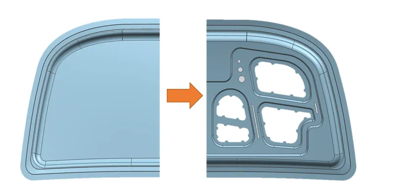
- The embosses were designed to avoid the crash force and distribute the impact forces on the outside which protects the passanger cabin and should meet NASC regulations.
- Those embosses are designed in a particular shape (Y or V shapes).
EURO NCAP Standard Followed:
- We build the hood panel for the protection of the people inside the cars, but we also have to protect pedestrians on the roads.
- This is what raises the car's standard and quality.
- When a car collides with a pedestrian, the pedestrian should sustain the least amount of damage possible.
- We must remove material from the inner panel of a certain area to accomplish damage.
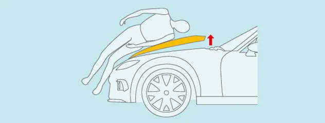
- The red line depicts the path of force dissipation when the hood attempts an unexpected crash.
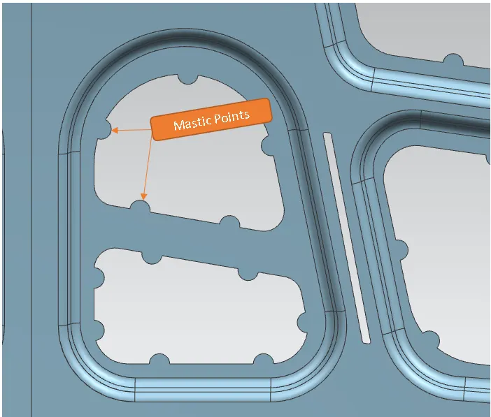
Mastic Points: Mastic points are the locations where mastic sealants are used to glue the inner and external panels together and prevent NVH.
Step 4: Creatng Hing emboss
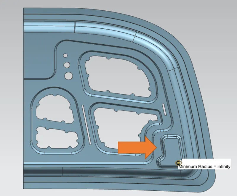
- Inside the hood assembly, the hing assembly must be extracted.
- Create a hing emboss with the referance of hing in a flat surface with the help of relevant datum.Flat surace avoid deformation while fastening the hing to the inner panel.
- On the surface of the hing emboss, the radius value should be 0.
Step4: Mirror The Model
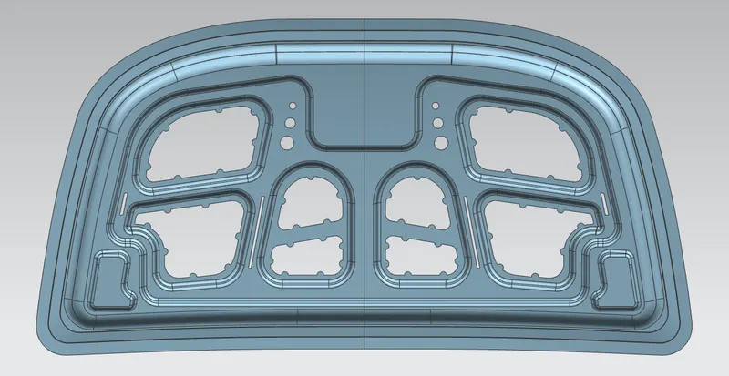
- Before mirroring the model, make sure there are no gaps available in the model.
- Use examine geometry commend to check for gaps.
Step 4: Position Analysis Of Striker
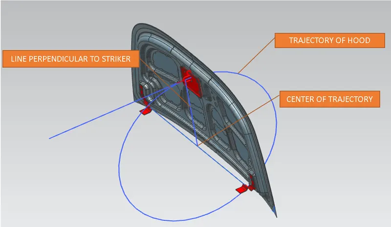
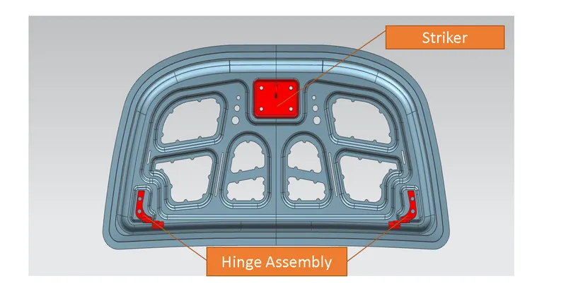
The striker's placement is importanct in ensuring good hood closing and determining the opening height of the hood.
The following steps shows the position analysis Of striker
- Find the hing axis's midpoint.
- Draw a circle with the centre at the midpoint of the hing axis.
- Make a line perpendicular to the striker.
- Line up the tangent of the circle with the striker's midline.
- The strike position will be determined by altering the circle radius.
Step 5: Assembly of striker and hing in inner panel.
- The straiker and hing should be mounted in the inner panel using assembly Constraints.
Importance Note:
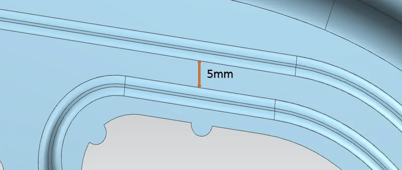
- The distance between two blend curves should be greater than 5 millimetres.
- The blend radius should be greater than 3 millimetres plus the model thickness.
- All of the sharp corners were blended and smoothed out using Edge blend and Face blend, as per the manufacturer's specifications.
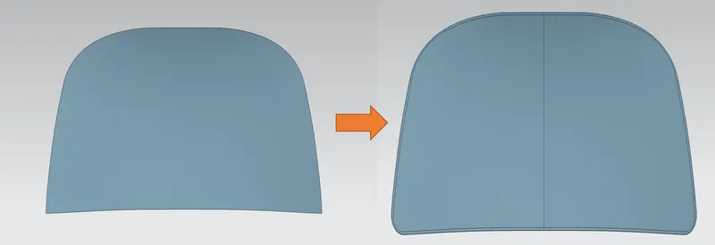
Step 6: Outer Panel Design
- Outer panel should be created with rear and front relief.
- Hemming should be given to prevent sheet overlap, which causes stress deformation.
Relief Rear Section:
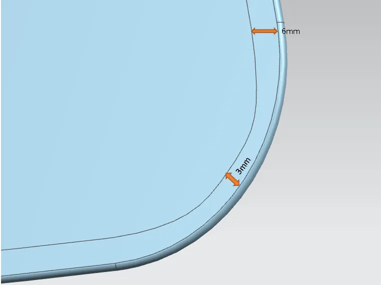
Relief front Section:
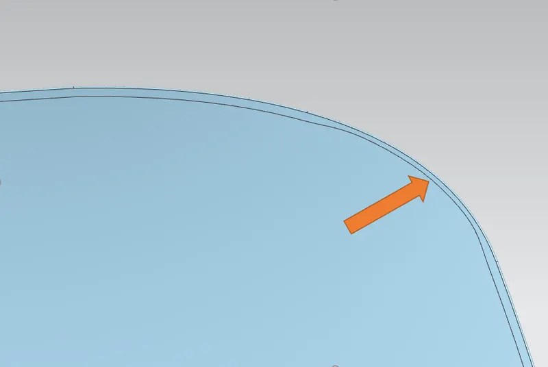
Hemming section:
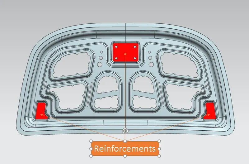
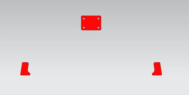
Reinforcements: These reinforcements are typically used to improve a component's mechanical properties, which helps to increase the component's strength and stiffness.
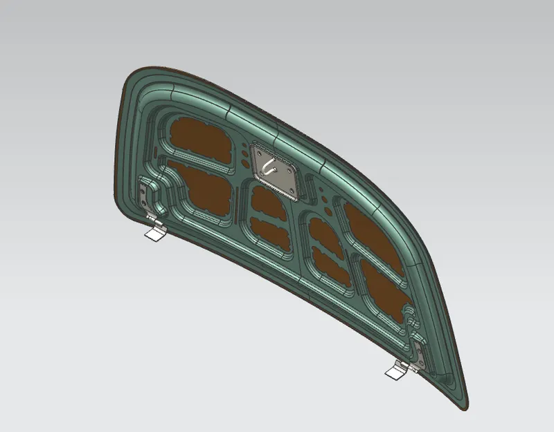
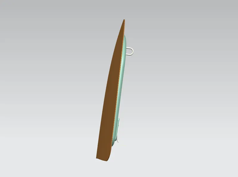
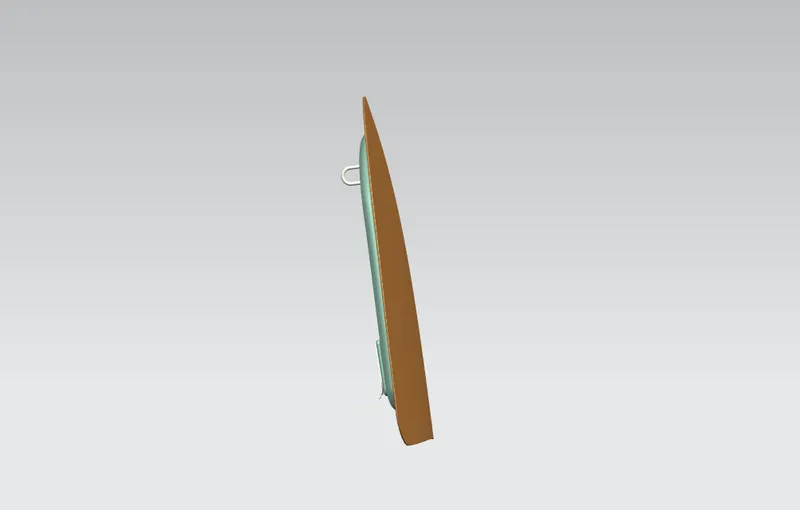
Final Assembly:
Front VIEW:
Back View:
Isometric View:
Side View:
Conclusion:
The master section is used to design the inner and outer panels, and the relevant design parameters are considered. A hood assembly with hing and striker is built, and a position analysis is performed on it.