Hood design-Week 2
REPORT ON DESIGN OF HOOD ASSEMBLY
Introduction
A car hood, also referred to as a bonnet in some other countries, is the hinged cover that rests over the engine of a front-engine vehicle.
It is the metal part that covers the engine of an automobile. The term car bonnet is a British term, used primarily in England, Ireland, Scotland, Wales, India, New Zealand, Australia, etc. Bonnet comes from the Old French word “bonnet”, which means cloth used as a headdress.
Hoods sometimes also contain a hood scoop, wiper jets, power bulge, and/or hood ornament.
The hood design may vary from one make and model to another, including SUV crossover, truck, minivan and passenger-car models.
Function of Hood

A car hood is meant to protect the performance parts of your vehicle, including the engine, while also providing easy access for repairs and maintenance.
A concealed latch is typically used to hold down the hood. On vehicles with an aftermarket hood and on race cars, hood pins may be used to hold down the car hood.
Concerns regarding the severity of a potential pedestrian head injury during a collision with a motor vehicle have led to advanced hood designs on many models. Such designs may include a multi-cone inner hood panel design. An active structure that is capable of pushing the surface of the hood away from the vehicle's hard motor components in the event of a pedestrian crash is also in use. Pyrotechnic or spring force designs are often used in active-hood design.
On front-engined cars, the hood may be hinged at either the front or the rear edge, or in earlier models (e.g. the Ford Model T) it may be split into two sections, one on each side, each hinged along the centerline. A further variant combines the bonnet and wheel arches into one section and allows the entire front bodywork to tilt forwards around a pivot near the front of the vehicle.
The hood release system is common on most vehicles and typically consists of an inner hood latch/lock handle, a hood release cable, and a hood lock assembly. The hood lock handle is usually located under the steering wheel, next to the driver’s seat, or in the door frame.
For racing cars or vehicles with aftermarket hoods (that do not use the factory latch system) the hood can be held down by hood pins. Some aftermarket hoods that have a latch system still have hood pins to keep the hood buttoned down if the latch fails.
NCAP Safety Ratings of Indian Cars
NCAP – New Car Assessment Program which highlights the safety feature in car including how well the car performs in various Crash Test (Front as well as Side).
The objective is to diagnose in occupant safety in case of collision and how well the safety equipment and features provides overall protection to car occupants including Adults and Children.
Various NCAP Agencies – Global NCAP, Euro NCAP, ASEAN NCAP, Australian NCAP are prominent in providing ratings to different car models sold.
While Global NCAP and Euro NCAP caters to developed markets, the ratings are slight more stringent as against ASEAN NCAP and Latin NCAP which caters to developing markets.
The Barrier test criteria are slight more stringent in Global NCAP and Euro NCAP.
Global New Car Assessment Program, or GNCAP, is a regulatory body that promotes universal adoption of the UN’s motor vehicle and safety standards. It acts as a platform for new car assessment programs worldwide with an aim to reduce road fatalities and improve pedestrian protection.
Each car under the GNCAP is given a rating based on a 5-star scale.
Global NCAP crash test process
The Global NCAP test, also known as a front offset crash test, involves the concerned vehicle moving at a speed of 64kmph. It forms a 40% overlap with a deformable barrier. Therefore, the resulting crash is equivalent to a head-on collision between two vehicles of the same mass moving at 50kmph.

Scoring global NCAP crash tests
Crash test dummies are placed inside the car before the test. These are fitted with specialised sensors, providing readings during the staged crash. The scoring is divided into two sections - Adult Occupant Protection and Child Occupant Protection.
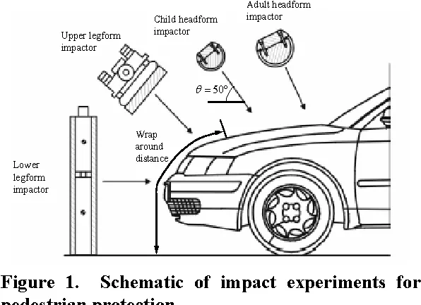
- Adult Occupant Protection scoring depends on 17-point testing.
- Child Occupant Protection scoring depends on 49-point testing.
After considering the scores in both these segments, a car’s final Global NCAP score is presented in star ratings, with 5 stars being the highest rated in safety and 0 star being the lowest safety rated cars.
Selection procedure for testing of cars under global NCAP
The Global NCAP agency buys cars from showrooms for testing. This process is initiated to ensure a baseline for each vehicle when it comes to safety. Apart from this, car manufacturers are also free to send in improved or upgraded models for testing. However, all cars are selected from the assembly line following stringent internal policies of Global NCAP.
MASTERSECTION OF CAR HOOD:
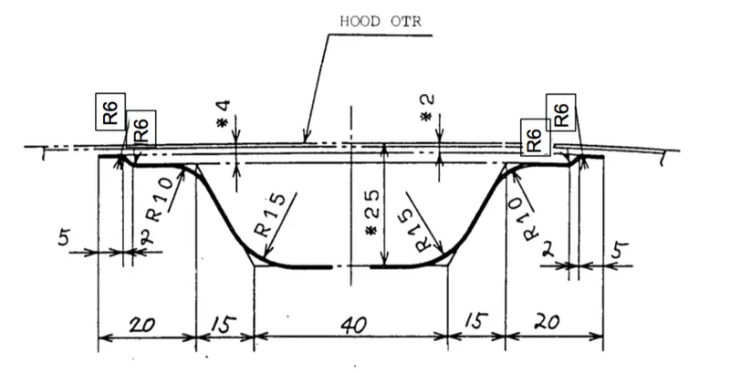
PARTS WHICH ARE INCLUDED IN CAR HOOD
- HOOD INNER PANEL:
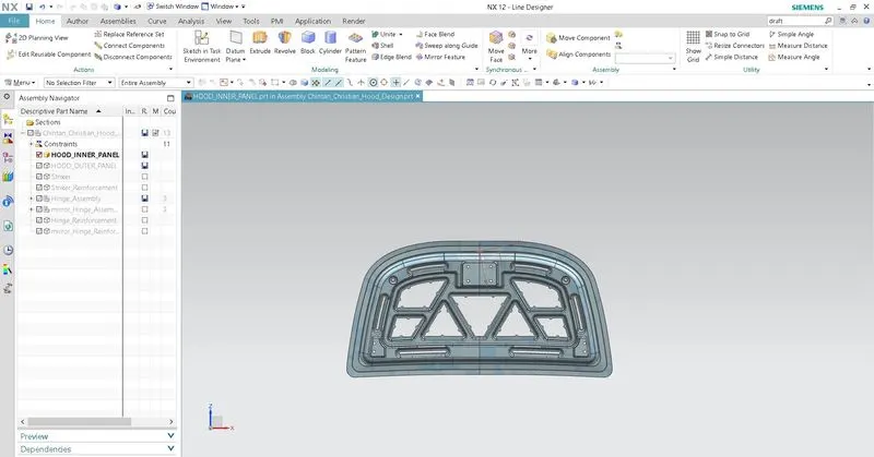
Purpose:
- To create safe cover for engine components.
- To protect car passengers in case of accident by rupturing itself as well as transmitting forces to strong members such as B Pillars.
- Some material is removed from it to weaken the structure, cost reduction and less severe injuries to person which got hit by car.
Process:
First, Working surface is required to create Hood inner panel. To do that, first trim the input surface given for Hood with plane in middle of it. Then offset this half portion at 0 mm & name it as ‘Working Surface’.
Here, hood inner panel thickness will be 0.75 mm and mastic sealant gap will be 0.2 mm.
So make first two offset surfaces with working surface at 2 mm and 4 mm respectively. Here one must add panel thickness into offset distance in downward direction. Use offset curve in face option for these two surfaces and trim surfaces as per required in Hood Master Section. Join these two surfaces using through curve option.
Add one more offset at 25 mm from working surface and make a law extension about 45 mm with 5° draft. Trim these surfaces using ‘Trim Sheet’ and add edge as well as face blends according to master section.
Create Embosses according to drawing. There should be 2 emboss layer required with height of 9.25 mm each and 5 mm gap required between Hood inner and outer panel for mastics expansion area. Here Hood inner & outer panel thickness as well as mastic sealant gap is considered for calculation of height of embosses. All the embosses should have 7 degree or more draft as per guidelines.
Mastics here used are of 10 mm diameter and minimum distance required for two mastics is 80 mm. Mastics are added on inside edges of emboss where material is removed.
Also, emboss is required for Striker and hinges. Here Emboss is created with datum plane which is parallel to Hood outer panel. These embosses are called emboss with flat face. All required edge blends are applied.
Holes in the striker as well as hinge emboss are created using extract geometry with composite curve option.
Then this half portion of Hood inner panel becomes completed by using mirror geometry option. Now these two portions of inner panel are joined by using sew with tolerance value of 0.01 mm. At last, Examine geometry option is used for checking any gaps in inner panel and then it is thickened by 0.75 mm in direction towards outer panel and in this way, HOOD INNER PANEL is created.
Features Used:
- Offset Surface
- Offset curve in face
- Trim Sheet
- Law extension
- Edge Blend
- Face Blend
- Extend Sheet
- Emboss
- Sketch
- Project Curve
- Offset Curve
- Trim and extend
- Extract Geometry
- Mirror Geometry
- Sew
- Thicken
- Examine Geometry
Why some material is removed from inner panel?
- To save weight and materials
- Retains nearly as much stiffness as it would without the holes
- The holes allow e-coating, surface preparation, and primer to drain from the cavities in between the hood skin and hood skeleton after the chassis is dipped into these during production.
- They also allow water, grime, and road surface treatment chemicals (salt, beet juice, magnesium chloride, etc) to drain from within the hood shell so the low points don’t rot out.
- The holes allow ventilation so that remaining water and grime can be mostly blown back out or evaporated.
- Water and ice treatment chemicals are the natural enemies of a car, especially one with a chassis built from thin sheet metal stamped and spot welded together. Capillary action and gravity hold the corrosive agents inside the spot weld seams and rot them out.
- So ventilation, drainage, corrosion protection, and seam sealing are critical to the longevity of a vehicle chassis. This is why every vehicle design has stereotypical locations where they will rot out first almost every single time. If more attention was paid to ventilating, sealing, and draining those areas, they would not rot as fast. The holes in the hood skeleton help with this situation.
- HOOD OUTER PANEL:
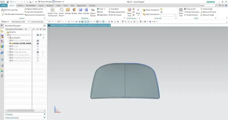
Purpose:
To present aesthetic look for appealing customers.
To Act as a cover on inner panel by joining these two with hemming process.
Process:
Here ‘working surface’ is created by using offset surface on Hood input surface at 0 mm distance in downward direction.
Now offset the working surface at 2 mm with adding inner panel thickness 0.75 mm and 2 times outer panel thickness 0.75 mm. Also add sealant gap of 0.2 mm 2 times.
It is required to add all dimension as given above to create a hemming flange for Hood outer panel. Now use offset curve in surface and create a law extension on it in both direction. Offset this law extension 15 mm inside for hemming purpose. Remove unnecessary portion using ‘Trim Sheet’ option. Use face blend with three faces option and create a hemming flange.
Apply hemming relief on corners by creating Curve on surface as per given image. Remove that portion using Trim Sheet. Mirror this half outer panel and joined them both using sew option.
Finally, add thickness of 0.75 mm to the outer panel in upward direction. In this way, Hood Outer panel is made.
Features Used:
- Offset Surface
- Offset curve in face
- Trim Sheet
- Law extension
- Face Blend
- Curve on Surface
- Mirror Geometry
- Sew
- Thicken
- STRIKER:
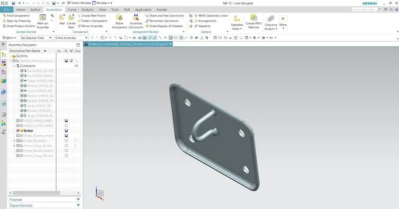
Purpose:
Its purpose is to create a tight fit between the hood and car body. They are hooks or bolts that latch up doors or panel on a vehicle.
Its plate is made of hardened metal which prevents wear of parts.
- HINGES:
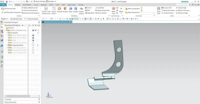
Purpose:
They are used for joining two parts together while allowing them to rotate relative to each other.
Hinges in a car are either welded or fixed with nut-bolt system to body of the system.
- REINFORCEMENTS:
Purpose:
To reduce noise level
To form stability as well as torsional rigidity
For impact protection
Size: Here thickness of all reinforcements is 1.5 mm.
- STRIKER REINFORCEMENT:
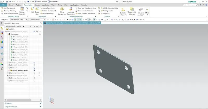
Process: Extract surface using Extract Geometry and thicken it.
- HINGES REINFORCEMENT:
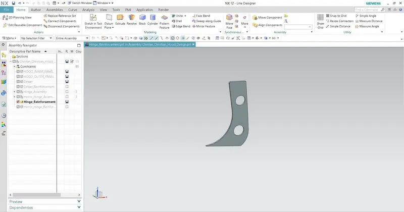
Process: Extract surface using Extract Geometry and thicken it.
LATCH AND STRIKER TRAJECTORY
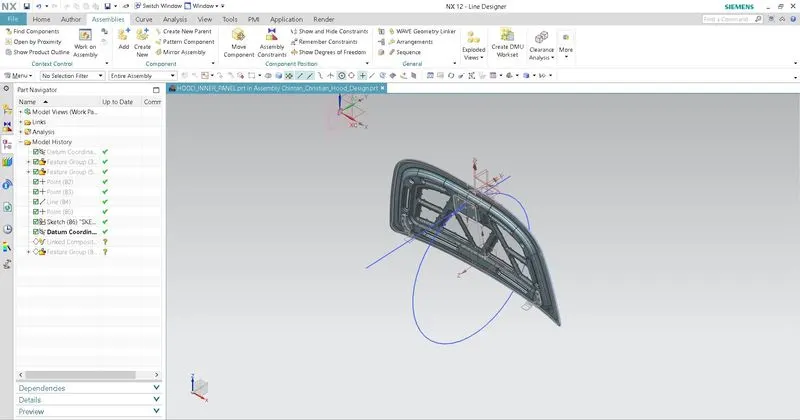
The importance of Latch and Striker Trajectory is to assemble latch and striker on car body perfectly to open or close car hood correctly.
First create a connecting line between two hinges. Then create a middle point on it & use it to make a Striker trajectory circle in relation to Hood Inner Panel. In the last, create a tangent and apply coincident it with Striker line as shown in Figure.
ASSEMBLY OF CAR HOOD
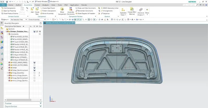
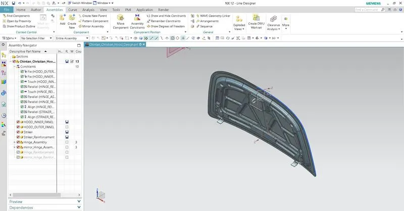
Fix Hood Inner and Outer Panel using assembly constraint.
First align the Striker reinforcement between Striker and Hood inner panel by using parallel and align constraints. Then apply same constraints with Striker.
Now, add the Hinge reinforcement between Hinge and Hood inner panel by using parallel and align constraints.
Then apply parallel constraint between hinge axis and X axis. Now align Hinge face with its support face in Hood inner panel. Adjust some distance if required.
Now use ‘Mirror Assembly’ option to mirror this hinge assembly on other side of Hood inner panel.
MANUFACTURING PROCESS
- Emboss:
Sheet metal embossing is a stamping process for producing raised or sunken designs or relief in sheet metal. This process can be made by means of matched male and female roller dies, or by passing sheet or a strip of metal between rolls of the desired pattern. It is often combined with foil stamping to create a shiny, 3D effect.
Process
The metal sheet embossing operation is commonly accomplished with a combination of heat and pressure on the sheet metal, depending on what type of embossing is required. Theoretically, with any of these procedures, the metal thickness is changed in its composition.
Metal sheet is drawn through the male and female roller dies, producing a pattern or design on the metal sheet. Depending on the roller dies used, different patterns can be produced on the metal sheet. The pressure and a combination of heat actually “irons” while raising the level of the image higher than the substrate to make it smooth. The term “impressing” refers to an image lowered into the surface of a material, in distinction to an image raised out of the surface of a material.
In most of the pressure embossing operation machines, the upper roll blocks are stationary, while the bottom roll blocks are movable. The pressure with which the bottom roll is raised is referred to as the tonnage capacity.
Characteristics
The metal embossing manufacturing process has these characteristics:
- The ability to form ductile metals.
- Use in medium to high production runs.
- The ability to maintain the same metal thickness before and after embossing.
- The ability to produce unlimited patterns, depending on the roll dies.
- The ability to reproduce the product with no variation.
Commonly used materials
The following materials are suitable for embossing:
- Aluminium (all alloys)
- Aluminium (T1/T2)
- Brass
- Card stock
- Cold rolled steel
- Copper
- Galvanized steel
- High strength, low alloy, steel
- Hot rolled steel
- Steel (all alloys)
- Zinc
- Deep Drawing process:
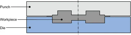
Deep drawing is a sheet metal forming process in which a sheet metal blank is radially drawn into a forming die by the mechanical action of a punch.
The process is considered “deep” drawing when the depth of the drawn part exceeds its diameter. This is achieved by redrawing the part through a series of dies. The flange region (sheet metal in the die shoulder area) experiences a radial drawing stress and a tangential compressive stress due to the material retention property. These compressive stresses (hoop stresses) result in flange wrinkles (wrinkles of the first order). Wrinkles can be prevented by using a blank holder, the function of which is to facilitate controlled material flow into the die radius.
Process
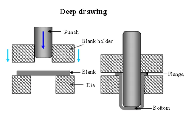
The figure illustrates the deep drawing process. The rigid tools consist of a punch, die and binder. In deep drawing, the plate holder closes after the metal sheet blank has been inserted.
Next the sheet is clamped between the die and the binder. This process slows down the flow of the sheet while it is being drawn and thereby prevents wrinkles from forming under the binder. The punch stretches the sheet over the die radius and forms it in the die. The amount of punch force necessary for forming is thereby continually increased up to the lower dead center of the punch.
Whereas in pure deep drawing there is no reduction of sheet metal thickness, forming is achieved in stretch forming purely as a result of a decrease in sheet metal thickness. Stretch forming is extensively used for the forming of only slightly curved parts with low depth of draw (e.g. roofs, doors).
When drawing complex car body parts in practice, there is usually a combination of stretch and deep drawing involved. It is necessary that the sheet metal is stretched as well as possible without reaching the material’s limits (e.g. splits, wrinkles).
There are approximately 300 to 400 sheet metal parts which fit together to form the body of a car. In order to manufacture high quality sheet metal parts optimally for their particular use, specialized software simulates the complete deep drawing process.
Commercial applications of this metal shaping process often involve complex geometries with straight sides and radii. In such a case, the term stamping is used in order to distinguish between the deep drawing (radial tension-tangential compression) and stretch-and-bend (along the straight sides) components. Deep drawing is always accompanied by other forming techniques within the press. These other forming methods include:
- Beading: Material is displaced to create a larger, or smaller, diameter ring of material beyond the original body diameter of a part, often used to create O-ring seats.
- Bottom Piercing: A round or shaped portion of metal is cut from the drawn part.
- Bulging: In the bulging process a portion of the part's diameter is forced to protrude from the surrounding geometry.
- Coining: Material is displaced to form specific shapes in the part. Typically coining should not exceed a depth of 30% of the material thickness.
- Curling: Metal is rolled under a curling die to create a rolled edge.
- Extruding: After a pilot hole is pierced, a larger diameter punch is pushed through, causing the metal to expand and grow in length.
- Ironing / Wall Thinning: Ironing is a process to reduce the wall thickness of parts. Typically ironing should not exceed a depth of 30% of the material thickness.
- Necking: A portion of the part is reduced in diameter to less than the major diameter.
- Notching: A notch is cut into the open end of the part. This notch can be round, square, or shaped.
- Rib Forming: Rib forming involves creating an inward or outward protruding rib during the drawing process.
- Side Piercing: Holes are pierced in the side wall of the drawn part. The holes may be round or shaped according to specifications.
- Stamping / Marking: This process is typically used to put identification on a part, such as a part number or supplier identification.
- Threading: Using a wheel and arbor, threads are formed into a part. In this way threaded parts can be produced within the stamping press.
- Trimming: In the Trimming process, excess metal that is necessary to draw the part is cut away from the finished part.
Often components are partially deep drawn in order to create a series of diameters throughout the component (as in the image of the deep draw line). It common use to consider this process as a cost saving alternative to turned parts which require much more raw material.
Other types of presses:
- Die-Set Transfer Press: Part is transferred via transfer fingers as the part progresses through the forming process. Tooling components attached to die plates enable the die to be installed in the press as one unit.
- ICOP (Individually Cam Operated Press): The part is transferred via transfer fingers as the part progresses through the forming process. Die components are installed in the press one station at a time.
- Progressive Die Press: The part is carried on the steel webbing as it progresses through the forming process.
- Hemming process:
Hemming is a forming operation in which the edges of the sheet are folded or folded over another part in order to achieve a tight fit. Normally hemming operations are used to connect parts together, to improve the appearance of a part and to reinforce part edges.
In car part production, hemming is used in assembly as a secondary operation after deep drawing, trimming and flanging operations to join two sheet metal parts (outer and inner) together. Typical parts for this type of assembly are hoods, doors, trunk lids and fenders.
The accuracy of the hemming operation is very important since it affects the appearance of the surface and surface quality. Material deformations, which occur during the hemming process, can lead to dimensional variations and other defects in parts.
Typical hemming defects are splits or wrinkles in the flange, material overlaps in the corner areas or material roll-in.
This is why it is important to use simulation tools in order to, on the one hand, better understand the hemming process and, on the other hand, significantly reduce the number of “trial and error” loops during try-out und production.
There are various types of hemming operations:
- Conventional die hemming
- Roll hemming
Conventional die hemming
In Conventional Die Hemming, the flange is folded over the entire length with a hemming tool.

Conventional die hemming is suitable for mass production. In die hemming, the flange is folded over the entire length with a hemming tool. Normally the actual hemming is a result of a forming operation in which the flange is formed with a hemming tool after the drawing and trimming operations have been completed.
The formed flange is then hemmed in several process steps. These steps include, for example, the pre-hemming and final hemming depending on the respective opening angle of the flange. Production plants for conventional die hemming are very expensive, but the cycle times are very low.
Roll hemming
In Roll Hemming, the hemming roller is guided by an industrial robot to form the flange.
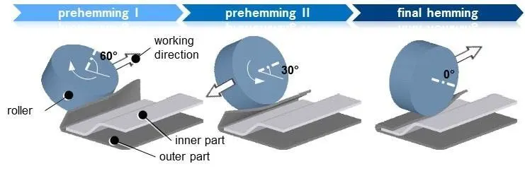
Roll hemming is carried out incrementally with a hemming roller. An industrial robot guides the hemming roller and forms the flange. Roll hemming operation can also be divided into several pre-hemming and final hemming process steps.
Roll hemming is very flexible to use and tool costs are significantly lower as compared to those of conventional die hemming. However, the cycle times are much higher since the hemming is realized using a hemming roller which follows a defined path.
MASTICS
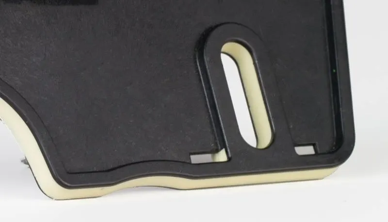
Mastic is commonly used on construction projects as an adhesive and sealant. It is a popular choice where one surface needs to be adhered to another in a durable bond, or where the area needs to be protected.
The most common types of material that mastic sealant can be adhered to include timber, aluminium, steel, marble, glass and various types of board, although it can be used on nearly all materials.
Examples of uses for mastic sealant include:
- Bonding ceiling, wall and floor tiles.
- Bonding plywood panels.
- As a joint-sealer for windows and doors.
- Sealing the area around bathtubs and other sanitary appliances.
- As a filler for cracks in masonry and concrete.
Mastic can be used outside because of its water-resistant, temperature-resistant and UV-resistant properties. It is also capable of resisting corrosion which makes it suitable for use with metals.
Although mastic will usually resist some applied pressure, it is not flexible enough to accommodate large movements. Due to its viscosity, it is best applied to thick rather than thinner areas of application, such as large gaps and cracks. Before applying mastic, the area may not require priming, but it should be clean and dry. It is best applied by using a caulking gun.
DRAFT ANALYSIS
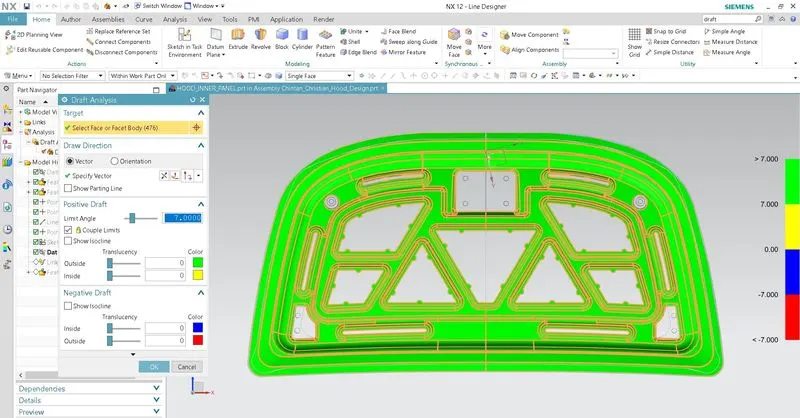
Here draft analysis of Hood Inner Panel is given.
In Hood inner panel design, one must use 7 degree or more draft for easy removal purpose with minimum damage.
Image of Draft analysis shows that areas marked with green colour shows draft of 7 degrees and more. Yellow colour shows draft less than 7 degrees.
CONCLUSION
In this challenge of Hood Design, I have learnt about various parts such as Hood Inner Panel, Hood Outer Panel, Striker, Hinge, Reinforcements & their purpose in design. Also, I have learnt about different manufacturing process used in car production such as Hemming, Deep Drawing, Emboss, etc.