Hood design-Week 2
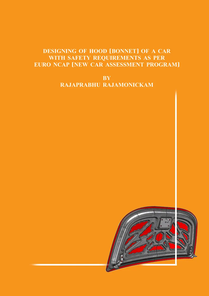
DESIGNING OF HOOD (BONNET) OF A CAR WITH SAFETY REQUIREMENTS AS PER EURO NCAP (NEW CAR ASSESSMENT PROGRAM)
AIM:
To design a hood of a car with its design requirements and safety requirements as per Euro NCAP (New Car Assessment Program) to get a good rating for the car.
INTRODUCTION:
Hood is defined as the front top of a car or other vehicle that covers and protects the engine, or a protective covering that removes fumes or exhaust.
The hood (North American English) or bonnet (Commonwealth English) is the hinged cover over the engine of motor vehicles. Hoods can open to allow access to the engine compartment, or trunk (boot in Commonwealth English) on rear-engine and some mid-engine vehicles) for maintenance and repair.
MATERIALS:
Hoods are typically made out of the same material as the rest of the body work. This may include steel, aluminum, fiberglass or carbon fiber. However, some aftermarket companies produce replacements for steel hoods in fiberglass or carbon fiber to make the vehicle lighter.
FEATURES:
A hood may contain a hood ornament, hood scoop, power bulge, and/or wiper jets.
Hood Ornament:
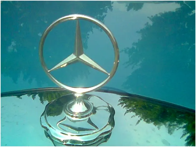
Fig. BMW hood ornament
A hood ornament (or bonnet ornament in Commonwealth English), also called radiator cap, motor mascot, or car mascot is a specially crafted model which symbolizes a car company like a badge, located on the front center portion of the hood. It has been used as an adornment nearly since the inception of automobiles.
Hood Scoops:
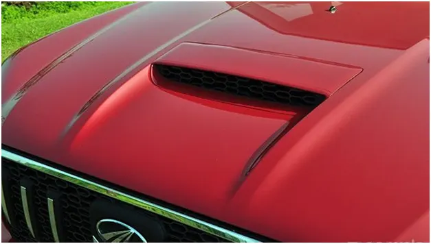
Fig. Hood scoop of Mahindra Scorpio
A hood scoop (North American English) or bonnet scoop (Commonwealth English), sometimes called bonnet air dam and air dam, is an upraised component on the hood of a motor vehicle that either allows a flow of air to directly enter the engine compartment, or appears to do so. It has only one opening and is closed on all other sides. Its main function is to allow a direct flow of air to the engine, hence the need for it to be upraised so as to effectively channel air to the engine compartment. It may be closed, and thus purely decorative, or serve to enhance performance in several possible ways.
Power bulge:
A hood scoop (North American English) or bonnet scoop (Commonwealth English), sometimes called bonnet air dam and air dam, is an upraised component on the hood of a motor vehicle that either allows a flow of air to directly enter the engine compartment, or appears to do so. It has only one opening and is closed on all other sides. Its main function is to allow a direct flow of air to the engine, hence the need for it to be upraised so as to effectively channel air to the engine compartment. It may be closed, and thus purely decorative, or serve to enhance performance in several possible ways.
Power bulge:
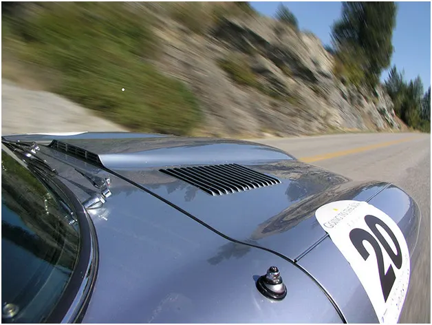
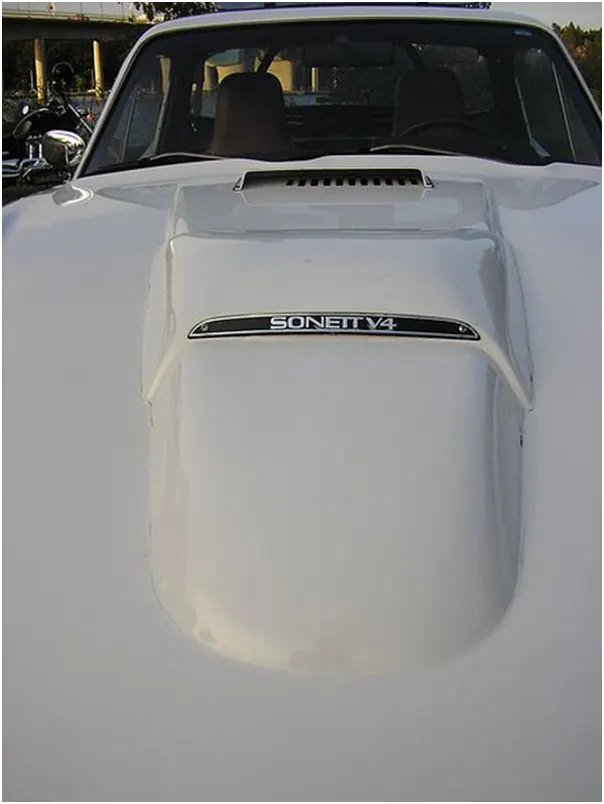
Fig. Power bulge In Sonnet cars.
A power bulge is a raised part (a bulge) of the hood of a car.
The reason for a power bulge is to fit, for instance, a large engine or air filters that otherwise would not fit. Sometimes a power bulge is used to be able to fit a larger engine into a car that originally was not designed for it or it may be a design choice to be able to get a lower profile. As a power bulge is associated with performance cars, it may also be used as a design element to give the impression of a fast car.
Wiper jets:
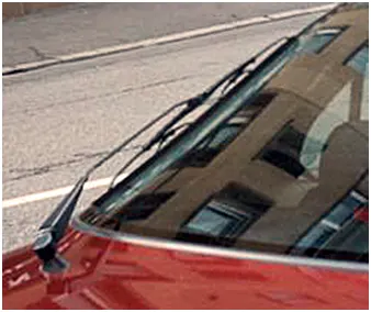
Fig. Windshield wiper.
A windscreen wiper or windshield wiper (American English) is a device used to remove rain, snow, ice, washer fluid, water, and/or debris from a vehicle's front window so the vehicle's operator can better see what's ahead of them. Almost all motor vehicles, including cars, trucks, buses, train locomotives, and watercraft with a cabin—and some aircraft—are equipped with one or more such wipers, which are usually a legal requirement.
RELEASE/ SAFETY AND SECURITY MECHANISMS:
The hood release system is common on most vehicles and usually consists of an interior hood latch handle, hood release cable and hood latch assembly. The hood latch handle is usually located below the steering wheel, beside the driver's seat or set into the door frame. On race cars or cars with aftermarket hoods (that do not use the factory latch system) the hood may be held down by hood pins. Some aftermarket hoods that have a latch system are still equipped with hood pins to hold the hood buttoned down if the latch fails.
PEDESTRIAN SAFETY:
In Japan and Europe, regulations have come into effect that place a limit on the severity of pedestrian head injury when struck by a motor vehicle. This is leading to more advanced hood designs, as evidenced by multi cone hood inner panel designs as found on the Mazda RX-8 and other vehicles. Other changes are being made to use the hood as an active structure and push its surface several centimeters away from the hard motor components during a pedestrian crash. This may be achieved by mechanical (spring force) or pyrotechnic devices.
PEDESTRIAN SAFETY THROUGH VEHICLE DESIGN:
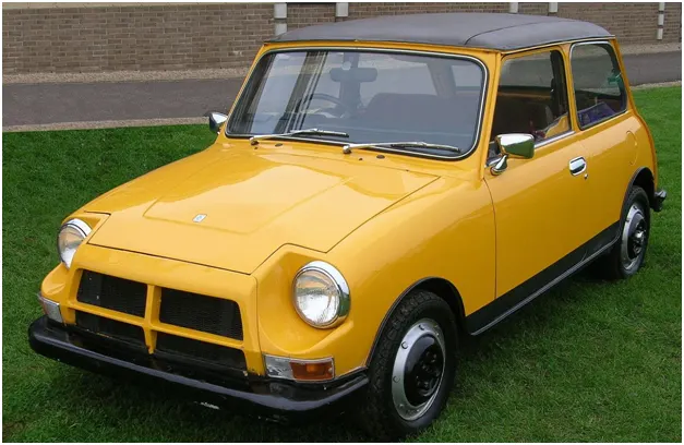
Fig. Mini Clubman SRV4, First pedestrian safety car made in 1974
In May 2013 the World Health Organization (WHO) reported that more than 270,000 pedestrians lose their lives on the world’s roads each year, accounting for 22% of the total 1.24 million road traffic deaths. Despite the magnitude of the problem, most attempts at reducing pedestrian deaths had historically focused solely on education and traffic regulation. Since the 1970s, crash engineers have begun to use design principles that have proved successful in protecting car occupants to develop vehicle design concepts that reduce the likelihood of injuries to pedestrians in the event of a car-pedestrian crash. These involve redesigning the bumper, hood (bonnet), and the windshield and pillar to be energy absorbing (softer) without compromising the structural integrity of the car. With the advent of ADAS (Automated Advanced Driver Assist Systems) since 2005, new pedestrian detection and crash avoidance and mitigation systems offer even greater improvements through active rather than passive protection systems. For example, omniview technology allows a driver to see what is a around the vehicle before moving.
The European New Car Assessment Program (Euro NCAP) is a European voluntary car safety performance assessment program (i.e. a New Car Assessment Program) based in Leuven (Belgium) formed in 1996, with the first results released in February 1997. It was originally started by the Transport Research Laboratory for the UK Department for Transport, but later backed by several European governments, as well as by the European Union. Their slogan is "For Safer Cars".
Euro NCAP is a voluntary vehicle safety rating system created by the Swedish Road Administration, the Fédération Internationale de l'Automobile and International Consumer Research & Testing, backed by 14 members, and motoring & consumer organizations in several EU countries. They provide European consumers with information regarding the safety of passenger vehicles. In 1998, operations moved from London to Brussels. It was supported by people like Max Mosley.
The programme is modelled after the New Car Assessment Program, introduced 1979 by the US National Highway Traffic Safety Administration. Other areas with similar (but not identical) programmes include Australia and New Zealand with ANCAP, Latin America with Latin NCAP and China with C-NCAP.
They publish safety reports on new cars, and awards 'star ratings' based on the performance of the vehicles in a variety of crash tests, including front, side and pole impacts, and impacts with pedestrians.
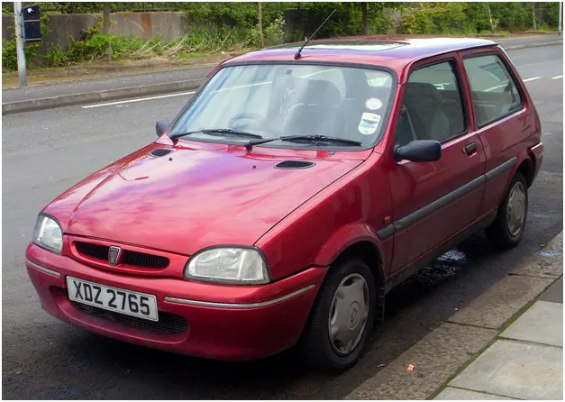
Fig. Rover 100
Testing is not mandatory, with vehicle models either being independently chosen by Euro NCAP or sponsored by the manufacturers. In Europe, new cars are certified as legal for sale under the Whole Vehicle Type Approval regimen that differs from Euro NCAP. According to Euro NCAP, "The frontal and side impact crash tests used by Euro NCAP are based on those used in European legislation. However, much higher performance requirements are used by Euro NCAP. Euro NCAP also states that "Legislation sets a minimum compulsory standard whilst Euro NCAP is concerned with best possible current practice. Progress with vehicle safety legislation can be slow, particularly as all EU Member States’ views have to be taken into account. Also, once in place, legislation provides no further incentive to improve, whereas Euro NCAP provides a continuing incentive by regularly enhancing its assessment procedures to stimulate further improvements in vehicle safety."
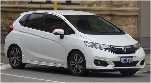
Fig. Honda Jazz
Before Euro NCAP was introduced car buyers had little information if one car was safer than the other; in fact the UK at the time required only a 48 km/h (30 mph) frontal crash test. The first ratings of a group of bestselling vehicles were released in 1997, since then Euro NCAP has tested more than 1,800 new cars, published over 600 ratings and has helped save upwards of 78,000 lives in Europe and encouraged manufacturers to build safer cars. The result of Euro NCAP is that over the years, European automakers' cars have become much safer. Test results are commonly presented by motor press, and in turn, greatly influence consumer demand for a vehicle. One notable example of this is the Rover 100 (an update of a 1980 design, first marketed as an Austin ), which after receiving a one-star Adult Occupant Rating in the tests in 1997, suffered from poor sales and was withdrawn from production soon afterwards: it was the 'What Car' car of the year, for 1980. BMW's 2007 MINI, for example, had its bonnet and headlamp fixture changed to meet the latest pedestrian safety requirements. In 2017, to celebrate Euro NCAP's 20th anniversary, they tested a 1997 Rover 100 and 2017 Honda Jazz under the same frontal offset conditions to demonstrate how far safety has come in Europe.
2020 TEST PROCEDURES IN EURO NCAP:
Mobile progressive deformable barrier:
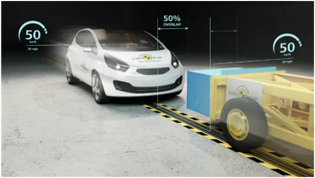
The test car is propelled at 50 km/h (31 mph) into a moving deformable barrier mounted on an oncoming 1400 kg trolley, also travelling at 50 km/h at a 50% overlap. This represents hitting a mid-size family car. Two adult male dummies are seated in the front (a THOR-50M driver and a Hybrid-III 50M passenger) and two child dummies (a 6 year old and a 10 year old) are placed in the back. The aim is to assess the crumple zones and the compatibility of the test car.
Full width rigid barrier:
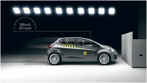
The test car is driven into a rigid barrier with full overlap at a speed of 50 km/h (31 mph). A small 5th Percentile dummy is seated in the driving position and in the rear seat. The aim is to test the car's restraint system, such as airbags and seat belts.
Mobile side impact barrier:
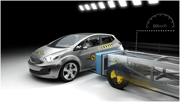
A deformable barrier is mounted on a trolley and is driven at 60 km/h (37 mph) into the side of the stationary test vehicle at a right angle. This is meant to represent another vehicle colliding with the side of a car.
Side pole:
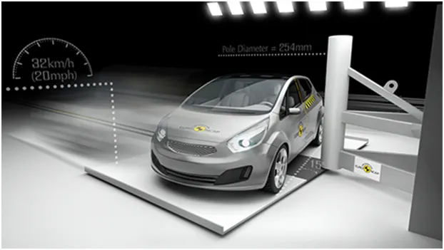
The car is propelled sideways at 32 km/h (20 mph) against a rigid, narrow pole at a small angle away from perpendicular to simulate a vehicle travelling sideways into roadside objects such as a tree or pole.
Far side impact:
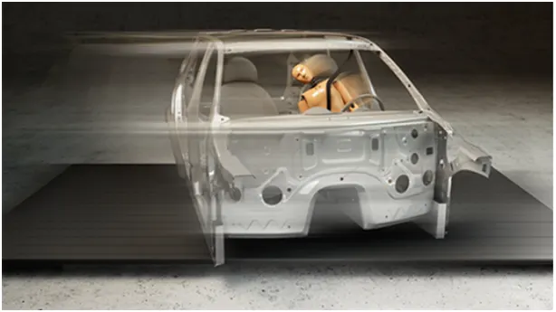
The body in white (frame) of the vehicle is attached to a sled is propelled sideways to provide accelerations experienced by the vehicle in the side and pole tests, but on the far side of the vehicle. The far side testing was implemented in 2020 to help combat far side injuries (where the driver is struck from the opposite side). The ‘excursion’ of the dummy - the extent to which the dummy moves towards the impacted side of the vehicle - is measured.
If the vehicle is equipped with centre airbags then a co-driver (front passenger) is added in either the mobile side impact or the pole test to evaluate its effectiveness.
Whiplash:
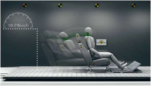
The vehicle seat is propelled forwards rapidly at both 16 and 24 km/h (9.9 and 14.9 mph) to test the seat and head restraint's capabilities to protect the head and neck against whiplash during a rear impact.
Vulnerable road users (pedestrians & cyclists):
- Head Impact:
- Upper Leg Impact:
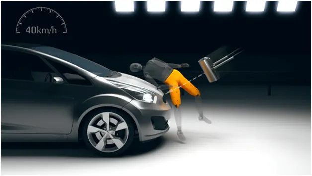
- Lower Leg Impact:
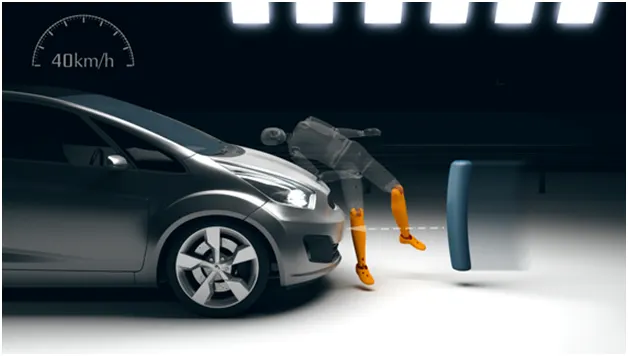
- AEB Pedestrian:
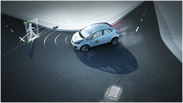
- AEB Cyclist:
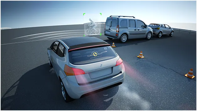
Safety Assist:
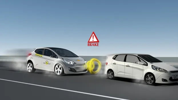
- AEB car-to-car:
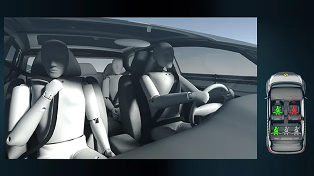
- Occupant status monitoring:
- Speed assistance:
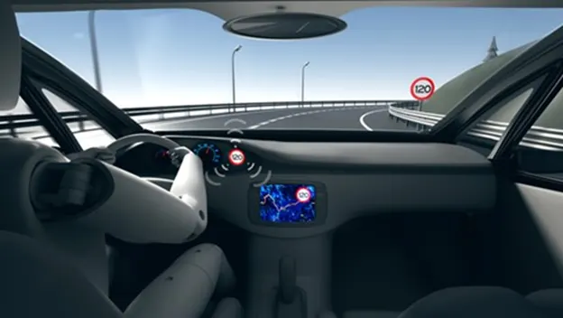
- Lane Support:

Rescue and extrication:
How easy it is for first responders to extricate the occupant and how well eCall performs after a collision.
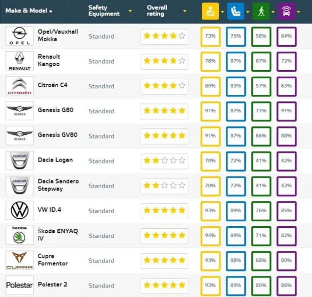
RATINGS OF THE CAR WITH SAFETY MEASURES BY EURO NCAP:
IN 2020:
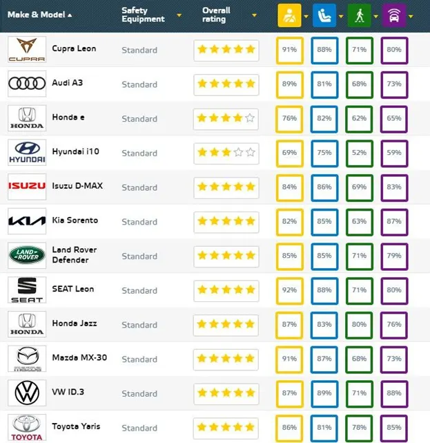
IN 2021:
Design consideration for hood:
The Hood is an opening body panel that covers the engine in a front-engine vehicle. The Hood is also considered as another type of door in a vehicle as it consists of an outer panel and inner panel. The inner panel provides strength while the outer panel functions as metal cover.
Hood is not that simple component what is seen from outside, this is also a very critical component because of the frontal crash and pedestrian safety requirements. Not only pedestrian safety requirements this is the one which dissipates the energy outside the car body rather than sending inside the car body.
The first important criterion for designing the hood is the region at which the car is developed.
OPENING ANGLE:
- As the opening angle varies from region to region, first we consider the opening angle according to the region where the car is developed.
In India and Japan Market the average height of the Human is 5.5ft (approx.), but in European and US Market the average human height is 6ft.
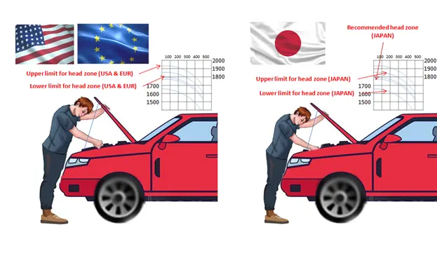
Fig. Hood Head Zone according to the region
On considering the region, the change in opening angle is controlled by the gas stay or support rod. Whenever you open the hood you will have a rod, used to dismantle and fix it to the engine compartment or you take it from the engine compartment and fix it to the hood. By predefining the length of the support rod varying opening angle can be achieved. Whenever the hood is opened there should be a clearance between the tip point of the hood to the striker.
Striker is the part which attach to the engine compartment from hood on locking and holds the hood with support rod/prop rod in open condition.
For opening the hood you will have normal lever/release latch inside the car below the driver seat or under the steering wheel, this is primary step.
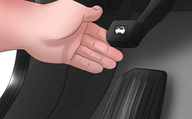
After this, now we can have the access to the secondary lever at front.
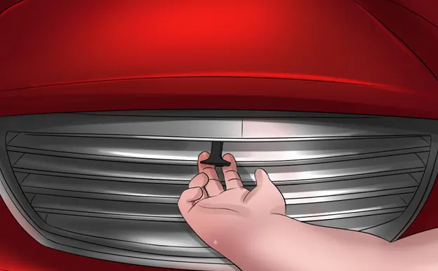
Whenever we release the primary latch, we should have space of 10-15 mm, so that we can easily access the secondary lever inside. The secondary lever will be a part of striker mechanism. We take this preliminarily, because whenever we start designing the hood we first consider about opening angle. If the opening angle is less there are high chances for the human to hit on the striker, which will create an injury. These are all the small points which could be addressed on a very early stage.
So, the first thing to be considered is which region the car is to be developed. And for this project, Japan is the region.
As we are going to design the car for Japanese Market, we take the head zones of JAPAN that included in the figure. (Hood Head Zone according to the region).
Study on Hood stay:
A hood stay is an apparatus for an engine room of a car, which can safety keep an engine hood in an open state even if an external force is abruptly generated due to vibration, wind and can facilitate an opening/closing operation of the engine hood. In other term, It’s a device for supporting the engine hood of a motor vehicle in its open position.
Purpose: An automotive engine hood is arranged to be opened for the purposes of inspecting the engine room, replenishing cooling water and / or engine oil, charging parts, making repairs etc.
Types of hood stay:
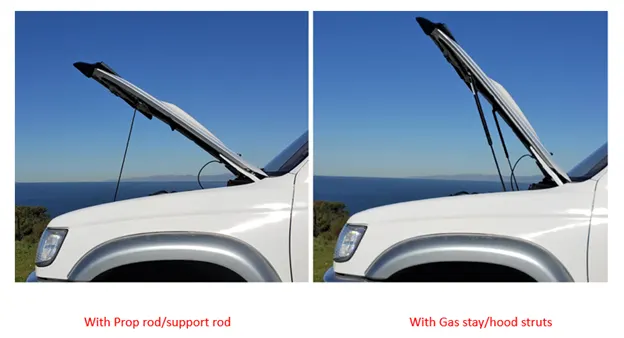
Fig. Hood stays
Support rod:
A device for supporting the engine hood of a motor vehicle in its open position by means of a rod.
Gas stay:
A device for supporting the engine hood of a motor vehicle in its open position by means of an actuator which is activated by gas.
To balance the hood, we seen about rods which is going to be placed under the hood/bonnet, sometimes it gets mounted to the hood from engine compartment and sometimes from the hood to engine compartment.
You can also use gas stay which will hold the hood on open condition.
When we start designing the hood, we have to think about the opening and then how we are going to hold the hood at open condition. (i.e. support rod or gas stay)
And then starts the technical difficulties,Once we get into support rod, we have to realize how we are going to position it. Is it respect to having it unmounted over the hood or unmounted over the engine compartment.
Whenever we prepare a support rod layout, we confirm where the opening angle is and where the closing angle is and where we going to mount this and where we going to dismount this. The length of the rod is defined w.r.t. opening angle of the hood.
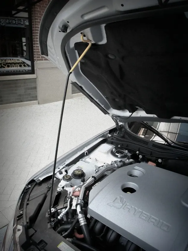
Fig. Support rod / Prop rod
Most of the cases when we mount support rod on engine compartment we have to do it on the opposite side of the battery compartment. This is because we prevent collision. Mostly the support rod is assembled before the battery is being packed. Which means the hood will be in open condition when you mount your battery. when you keep hood at open condition, and you have support rod on other direction it makes easy for us to mount the battery.
Design consideration for the gas stay:
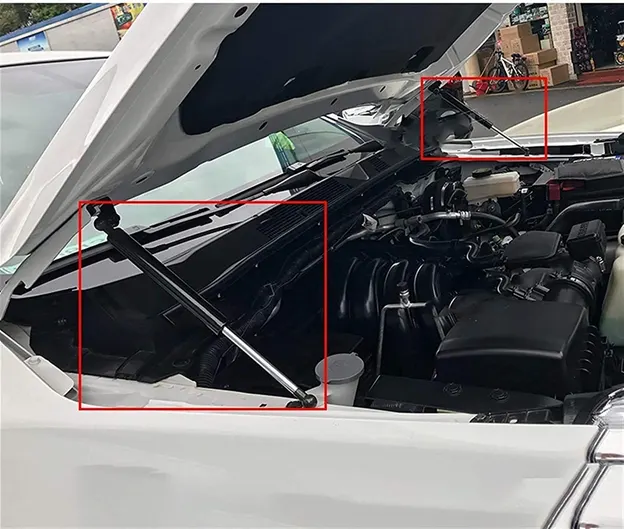
Fig. Gas stay / hood strut
For gas stay we will consider the outer panel and inner panel design and we will have to take the centre of gravity of the hood assembly to the engine compartment. Since gas stay is an additional commodity, we will use additional bracket as the gas stay have to maintain a weight of 8-9kg hood assembly. Only when the hood is becoming heavier, we think of using a gas stay. Because it is difficult for the human to open the hood completely. This is normally happening on high performance based cars where the hood length will be really big and it is really be difficult for you to access the hood. On those situations we use a gas stay. Where you give a initial effort and the hood will go above and when you initial thrust it automatically closes inside.
Design consideration in Hood for better pedestrian rating:
To justify the hood, we have to first study the type of the hood.
Hood is of two different type:
- Inlaid hood:
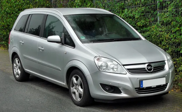
Fig. Opel Zafira, an example for inlaid hood.
- Wrap around hood:
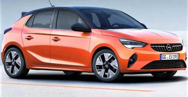
Fig. Opel Corsa, an example for wrap around hood
When we take a 45 deg angle line (i.e side reference line) from the ground, if the line first touches fender of the car it’s an inlaid type hood and if that line touches the hood first then it’s a wrap around type hood.
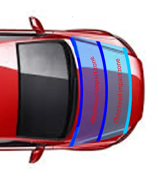
Fig. Head Impact zones.
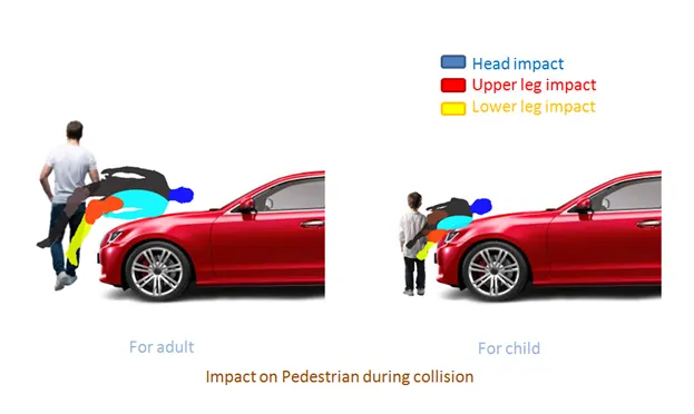
The side reference line is studied to understand the head impact as per EURO NCAP. As we seen earlier EURO NCAP is a which analyze the test that got to be carried over to understand how much the car is safer for the pedestrian.
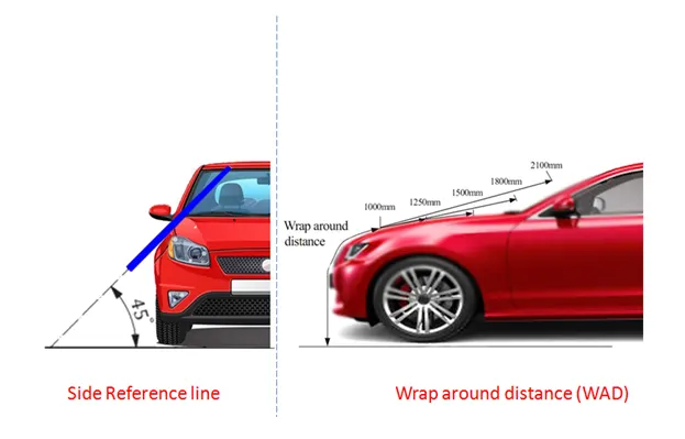
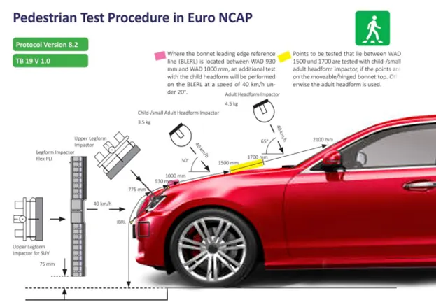
When we get the skin data of the hood we also check this, we will check the side reference line for the car. If the car has an wrap around hood the head impact is less. Whenever there is a collision with the pedestrian, he tent to hit in the hood/bonnet. These hitting is defined with child head impact zone and adult head impact zone. WAD(Wrap around distance) distance is the distance from ground till the hoods end.
If my side reference line is falls more outside(on fender), the wrap around distance(WAD) will be more and impact zone will be less. If the side reference line falls on the hood, the WAD will be less and impact zone will be more.
Hood design on the tool:
Now getting into the hoods design on the tool,
The outer panel is given as a skin data. Which is the one what we get from the styling team. We are going to study the engineering feasibility and reporting them whether this styling is possible or not. And at the same time we will also tell little feedback on modifications what can be done or in the mean time we can tell about the modifications which is needed that styling looks feasible.
While getting into the hood design we will have to first define the edges of the hood, which attaches to the engine compartment. We have a predefined edge from the styling team. If we have some changes in the design of engine compartment we will have to modify the edges according to the edges of the engine compartment to match, this is what the engineering in designing this. For doing this we will have master section, which is predefined sketch which is adoptable on different situation.
When I section the hood will be like this. As from the given data the hood outer panel thickness is 0.75 mm. then we start preparing the inner panel. We have to take a 25 mm offset from the styling surface which has been received from the styling team. Because of the pedestrian safety the 25 mm offset is provided.
As we have given with the master section below, we start design the inner panel.
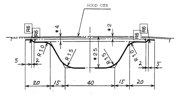
Fig. Given Master section which is from the previous car.
From this master section we design our hood inner by offsetting the skin data provided.
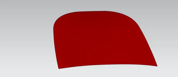
Fig. Given skin data (Hood outer panel)
Steps involved in designing the hood inner panel:
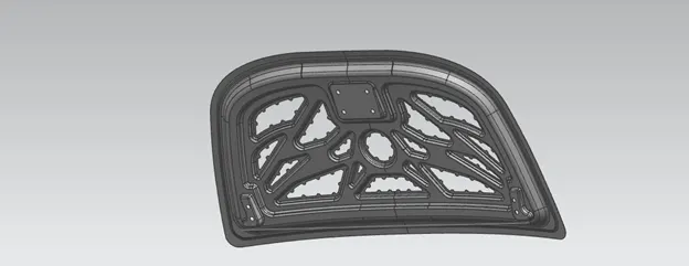
Fig. Hood inner panel.
- Offsetting the skin of outer panel.
- Creating the flanges with reference to the master section.
- Creating the embosses inside.
- Creating hinge emboss.
- Creating the striker emboss with the help of latch trajectory.
For producing the hood we normally deep draw the part. Most of the steel parts are deep drawn. When there is deep drawing process, one will have to stamp the part. We define the geometry and open the part a lot to provide the tool to come in and go out during stamping.
Deep drawing:
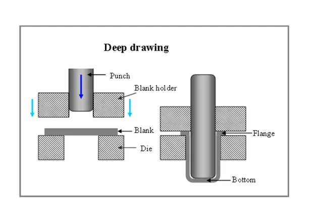
Deep drawing is a sheet metal forming process in which a sheet metal blank is radially drawn into a forming die by the mechanical action of a punch.
It is thus a shape transformation process with material retention. The process is considered "deep" drawing when the depth of the drawn part exceeds its diameter. This is achieved by redrawing the part through a series of dies. The flange region (sheet metal in the die shoulder area) experiences a radial drawing stress and a tangential compressive stress due to the material retention property.
Embosses in the inner panel:
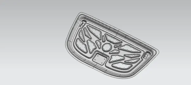
Whenever the collision happening the force goes straight. We as design engineers have to try dissipating the force to outside the car as early as possible. So that we create embosses in such a way, that the force direction changes towards the hinge. As a design engineer, It’s our responsibility to dissipate the forces on the way of embosses. So that it doesn’t goes directly straight and make the force do dissipate towards the hinge. During this situation the energy what we experience during collision will reduce a lot, so that the passengers inside the cabin not get affected. We cannot give 100% guarantee that the passenger will not at all be affected, the force which is getting inside the cabin will reduce drastically with adding embosses like this.
Latch and striker position(latch trajectory):
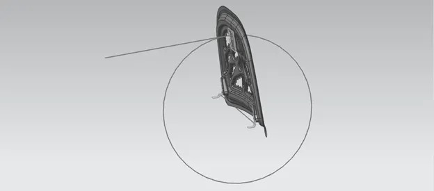
To check the correct position for latch and striker we have to go for a study. This study is similar for all closure components like hood, side doors and back door. Whenever we design a swinging part this concept is implemented.
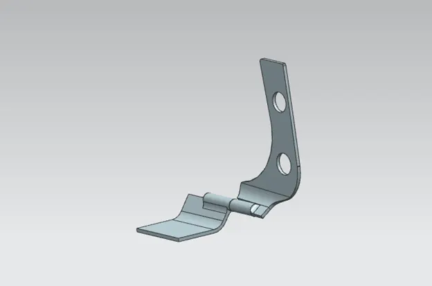
Fig. Given hinge assembly part
As we are already provided with the hinge from the previous car we just assemble the hinge with inner panel to achieve the trajectory and we have also given with latch and striker from the previous car.
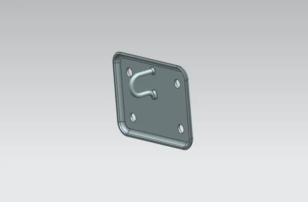
Fig. Given Striker part.
This striker part is also used to validate the trajectory.
The hinges are the part which is going to connect the engine compartment to the hood and these hinges are going to be in same axis. On defining the hinge axis, we will be going to position the hinge speculatively/trial based. By positioning this we get a hinge axis point. We predefine the latch and striker position from the previous vehicle and we validate that position for our current model. From the hinge axis we draw a circle which meets the striker center point.
From the circle we infer two points:
This circle is the trajectory of the hood open and closing. In this situation if the striker is exactly perpendicular to the trajectory on the striker region locally, then my hinge position is correct. Or else we will have to move the hinge or striker inside or outside to get the exact perpendicular nature. Speculatively or on trial based we start draw a circle to define the trajectory of the hood part and also the hinge axis. At one position we will have the perpendicularity achieved and proper hinge axis achieved. Then the hinge axis and the striker point are all correlated. If we the hinge axis we will have to move the striker point. If you move the striker point, you will also move the hinge axis just for maintaining this perpendicularity.
Main reason to maintain this perpendicularity is, this controls the trajectory. The trajectory is the way that the striker is going to in contact with the engine compartment. When it comes to the engine compartment, we will have the latch. This latch is positioned w.r.t the trajectory. If it’s not perpendicular, you will not have proper closing. Your closing will become hard. When closing becomes hard the customer feels it as a concern, when the customer feel it as a concern that will make a reduce in the sales volume. The first point what we do is, we will define the striker section then I define a speculative / trial based hinge axis and see the perpendicularity and the trajectory of the hood to understand where the hinge axis is. Once we got the hinge axis, we will give an local emboss to place reinforcement. Because we lose some strength. When we lose the strength, we need additional reinforcements to compensate that. we produce reinforcement and assemble the hinge and its reinforcements. When we design the closure component like this we have to first determine the hinge axis. Rotation is possible if there is an hinge axis. So positioning the like this is the very important point. Once we position the hinge w.r.t its axis we get the striker position. We can validate the position by achieving the trajectory. So all these three points are correlated. Embosses are upto the designers freedom and the drawability and CAE team will study and tell us whether this right or not.
Hemming:
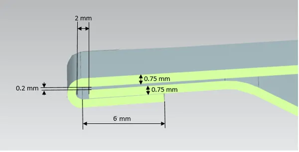
Fig. Provided hemming data.
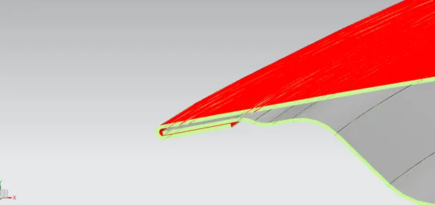
Fig. Inner panel and outer panel with hemming
We already designed the inner panel and outer with the thickness of 0.75mm. After that when we join these panels we will produce the bends along the edge of the outer panel towards inner panel. These bending process is called hemming. By doing this with provided nomenclature we avoid spot welds.
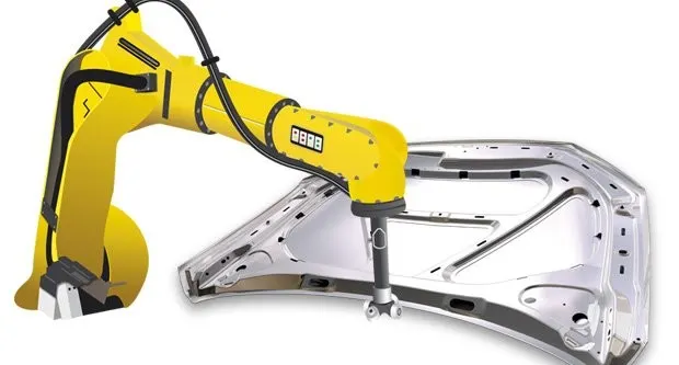
And when we do the hem, on the corner of the hood outer panel we have to give the relief.
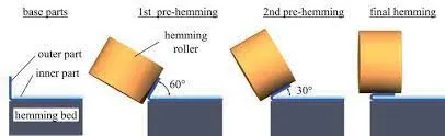
There will be different rollers assembled on different corners. Each rollers will roll over the edges of the sheet metal to close it with the inner panel. And these rollers will roll two or three times to enable perfect rolling provided with different rollers. To avoid intolerance issues we do hemming with different rollers and it will also saves time.
On first roller pass, the minimum closing is happened.
On second roller pass, it completely close the corners and
On third roller pass, it justifies the closing what it attends.
Normally hemming is done for assembling the outer panel with inner panel. And when you pass the rollers over the sheet metal there are some tendency that the sheet metal vibrates. Simulation team also studies that is these force making the panel come back to its original position or it is changing the design of the part. That is what the spring back effect is.
Reliefs:
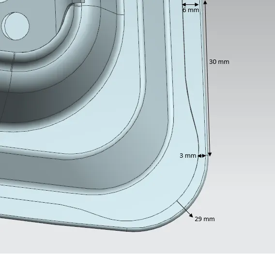
Fig. Given rear relief data.
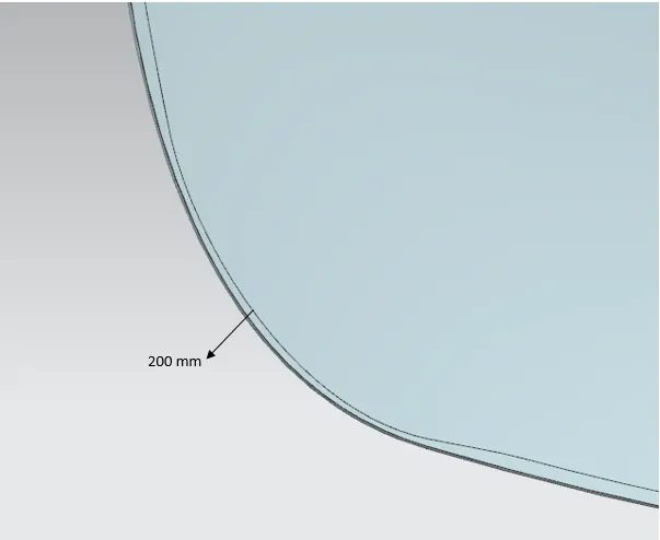
Fig. Given Front relief data.
As we design the outer panel by simple offsetting the skin provided, these relief should be provided to completely design the outer panel.
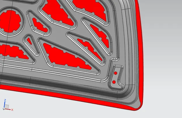
Fig. Outer panel with rear relief
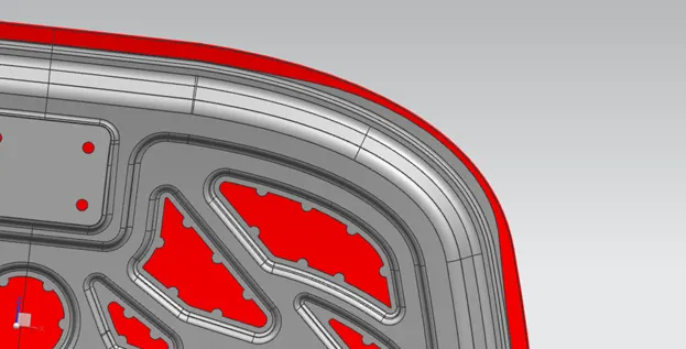
Fig. Outer panel with front relief
The force what is been used to join outer panel and inner panel, is that really sufficient for doing the hemming operation is the first thing consider in this. If it is too much whether its disturbing the outer panel design is the next thing, if that force bring back the outer panel to its outer panel to its original state then the force what we have used is right. Or else that becomes the problem and those zones are consider as red zones. To avoid those kind of red Zones we normally give a relief on corners. So that we don’t any complete roll by the rollers on that region, it just provides a little roll and then goes out. And all the corner we use the reliefs for this purpose.
Reinforcements:
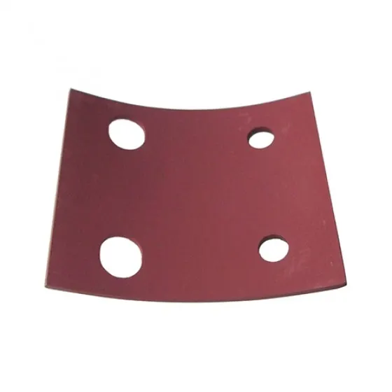
Fig. Striker reinforcement of Jeep
Whenever we add a weight to a material, we lose the strength of material locally.
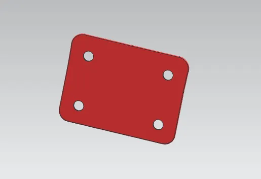
Fig. Striker reinforcement.
We designed this latch by taking reference from the emboss created for the striker in the inner panel. We have given 1.5mm thickness to reinforcement as per given data from the previous car.
To compensate the loss of weight while adding the latch and striker in the inner panel we add reinforcement. This we called latch and striker reinforcement.
Hinges and Hinge reinforcements:
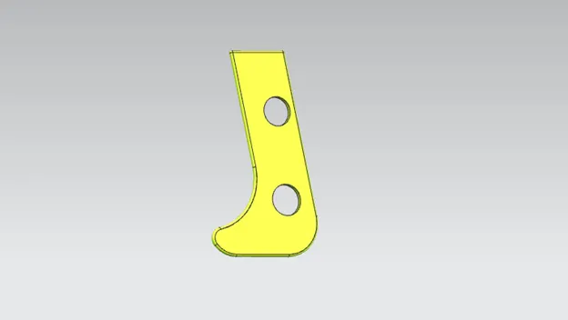
Fig. Hinge reinforcement.
We create this reinforcement with reference to the hinge emboss created in the inner panel.
Without a hinge there cannot be a motion. To have a open/close motion, we need a hinge which is actuating and we need axis over which this motion will act. So when placing some hinges, we again loosing the strength. To compensate we add additional material which we called hinge reinforcement.
Reinforcements are the part which is added to compensate the lose of weight locally. Intentionally given to improve the strength of that area locally.
Stiffener pad:
Stiffener pad doesn’t have predefined shape, which looks like an hardened sponge. It is placed between inner panel and outer panel to improve the strength locally. While in motion the hood withers. To avoid this vibration for NVH, we add stiffener pad. Most of the time stiffener pads are used in the initial stage of the project and removed later due to cost reduction production process.
Mastic data:
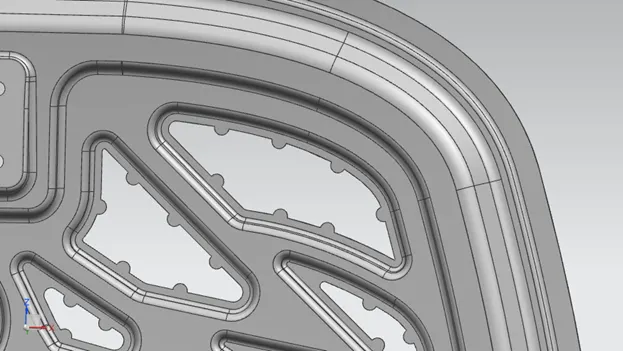
Fig. Inner panel with mastic data
It is an NVH based thing. Every mastic sealant has the tendency of improving the strength locally around 60-80mm diameter. We will position the mastics in such a way that most of the hood regions are covered.
Mastic sealants are the small hardened rubber part. We will introduce this as paste inside between the outer panel and inner panel. And when it gets into the hot furnace will attach the inner and outer panel as sealants.
As hood outer panel is a styling surface, if we place any spots with spot wells the outer panel won’t looks that good. Always on the styling surface we will not add any spots or any negative grades which will reduce the aesthetics of the car. We only add the spots, riveting on the inside parts of the car. We will influence the spots and riveting on the skin panels. Skin parts won’t fit for rivets and spot welding.
So for that only we have introduced new joining techniques like hemming, gluing and mastics.
Now we have seen the importance factors like:
- Head zone criteria, that how do we open and close the hood,
- Hood balancer and
- NVH criteria
These three are the important topics on designing the hood. We will have to keep these points when we design the hood.
Mastic points:
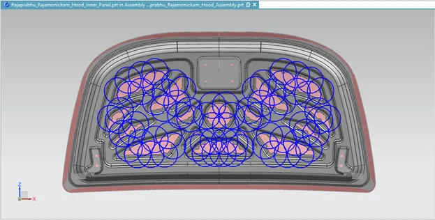
We also give the region for the mastic points. These regions are closer to the outer panel inside, where you apply the mastic sealants and start gluing the panels. Due to heat the mastic whoosh out and gets sticks. Above this master section structure we add more embosses on the part to enable the stiffness of the part.
Sometimes the gap between the inner panel and the outer panel should be matched to get the mastic influences.
Now we have designed the hood as per the requirements.
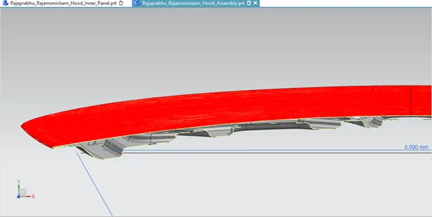
Fig. Cross section view of inner panel and outer panel.
Final Model of the hood with its part assembled:
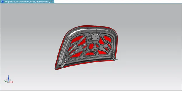
Orientation views of the hood assembly with hinge and striker along their reinforcements:
Isometric View:
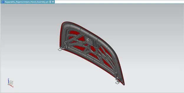
Front View:
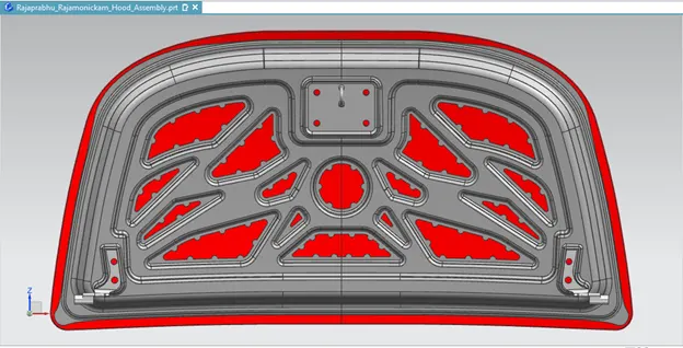
Top View:
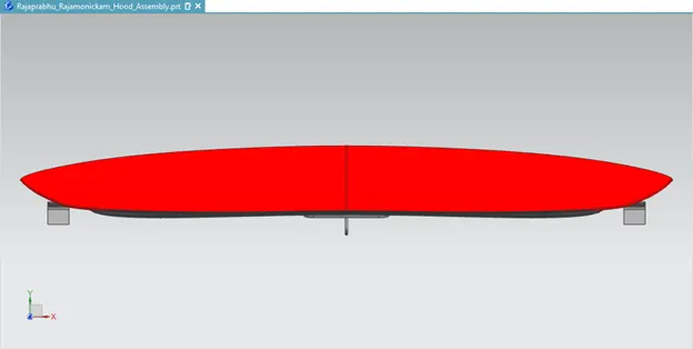
Right View:
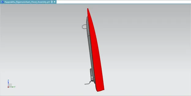
For better star rating in Euro NCAP:
While getting the skin data, we have study the WAD and how much is the Head impact zone area.
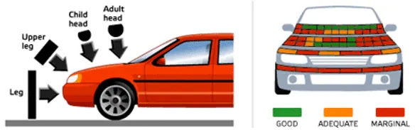
If we increase green region more and red region less. We will get a good car rating in the EuroNCAP and that’s what our design consideration is. As a design engineer. After designing the inner panel for collision and support, we start removing the material to soften the part on that area when the part becomes softer, the force what is extracted will be less, if a person hit on the material removed area he gets less impact than on the other area. On designing the hood as hood engineer we have reduce the no. of red points and increase the green points.
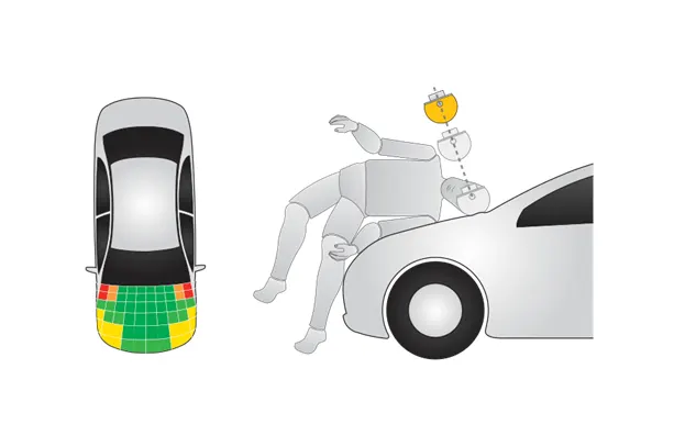
Sometimes to reduce red points we can also produce small bracket which deforms easily during collision. On collision these brackets gets deformed and the force exerted to the human is less. This means that when we giving these bracket we improve our green zones. At the time the red zone becomes yellow. It is also been done for head leg and pelvis.
The dummies are used to measure most of the incidents and an average mean value is taken and the car is rated.
So for designing the hood we consider so many things like NVH, hood stay mounting, latch and striker point,hinge axis, deformable brackets, pedestrian rating and EuroNCAP regulation for designing the hood. Which looks very simple from outside.
Head Impact:
About 14 percent of all road fatalities in Europe are pedestrians, with children and the elderly being at greatest risk. Pedestrians comprise one of the main categories of vulnerable road users, which also include cyclists and motorcyclists.
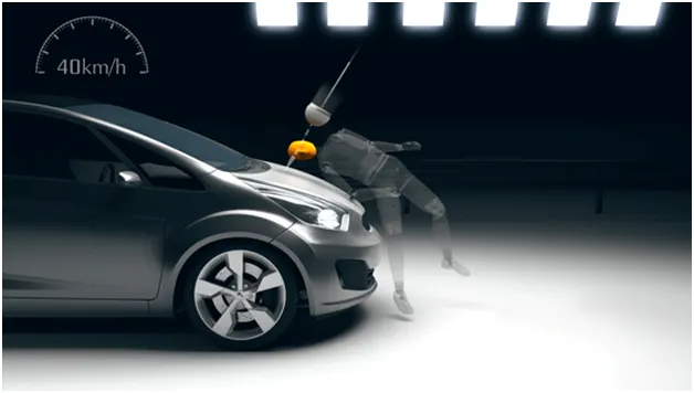
Most pedestrian accidents occur within city areas where speeds are moderate. The head, the lower body and the legs are amongst the most frequently injured body regions. To estimate the potential risk of head injury in the event of a vehicle striking an adult or a child, a series of impact tests is carried out at 40 km/h using an adult or child head form impactor. Impact sites are then assessed and the protection offered is rated as good, adequate, marginal, weak or poor.
The procedure promotes energy absorbing structures, deformation clearance and deployable protection systems such as pop-up bonnets and external airbags.
To reduce this head impact is the primary measure for designing the hood apart from its engine closure and frontal crash functionalities. So, We considered this in designing the hood by leaving some cutouts inside the embosses made in inner panel. That is the region that clearly shows the outer panel from inside. These cutouts are provided for the safety requirements.
Recent trends in hood assembly considering Pedestrian safety:
As the hoods are the prior thing reduce the impact on pedestrian mainly the head, the top car companies are implementing the new system. Below are the two new trends in hood assembly.
- Pop up hoods
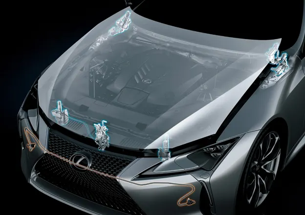
When the car hits a pedestrian, a sensor in the bumper signals the pop-up control unit, which judges its necessity, will trigger an explosive actuator that pops the hood up.
When it is adapted low bonnet height cars with little space between the hood and engine parts, the feature achieves a two goal: allowing sporty styling while helping to protect pedestrians from head impact in collisions.
- Pedestrian air bag technology
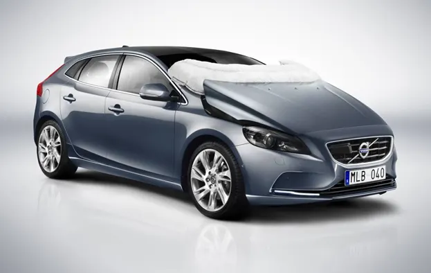
The pedestrian airbag technology as being one possible solution to cushion an impact helps to protect pedestrians in collision situations.
Sensors embedded in the front of the car (bumper) transmit signals to the pedestrian airbag control unit. When the car comes into contact with an object, the signals change. The control unit evaluates the signals and if it registers what it interprets as a human-like leg the pedestrian airbag technology is activated.
Hope these features emerges in all cars in order to provide more pedestrian safety.
Conclusion:
The model of a hood of a car is successfully designed with its design requirements and safety requirements as per Euro NCAP (New Car Assessment Program) to get a good rating for the car.
- Surendra GembaliHI bro, just I have read through report. it is too good. I have a small doubt could you please help me with that?
- Rajaprabhu RajamonickamYes bro. Thank you. I try my best to help you. Ask me.
- Surendra Gembalicurrently I am doing master's in London bro and my thesis is going on hood designs. I hope your report definitely help me as a reference for my research so is it possible for you to send me this report?. if yes please ping me in WhatsApp bro and my number is +918332038062
- Rajaprabhu RajamonickamSure bro. Good luck on your Thesis and Master's degree.