Photo Realistic Rendering
MODELING OF AMERICAN CHOPPER IN SOLIDWORKS.
OBJECTIVE:
To design a model of American Chopper using SolidWorks CAD software with basic features like sketching a geometry and composing it into 3D Model and rendering it to visualize as a realistic object.
INTRODUCTION:
Modeling:
A Model is a mathematical representation of a geometric form, which is stored in the computer memory. 2D Models are recognized by the system as flat frameworks bounded by a number points, which are defined by X and Y Cartesian coordinates. A 3D Model may be held in computer memory by specifying points with a third Z coordinate.
Viewing an object in 3 dimensions helps to get a sense of its true shape and form. It also helps in design, which in turn allows us to make better design decisions. It helps to communicate our ideas to those who may not be familiar with the orthographic views including sections and side views of design.
In this project we are going to see the entire modeling of an American Chopper in SOLIDWORKS.
Solidworks contains the capabilities to produce 3D Models. These capabilities are used interactively with 2D drawings.
The different components of the motorcycle we deal with are:
- Engine with exhaust system.
- Front Wheel and Rear Wheel with rims, sprockets and calipers.
- Chassis.
- Front fork along with handlebars and grips.
- Oil Tank and Gas Tank (Fuel Tank).
- Chain and Transmission belt.
- Front and Rear Fenders.
- Kick Stand and Foot Pedals.
After designing the part components, we have work upon the assembly and the Photo rendering of the chopper which gives the model a complete and realistic view.
DESIGN METHODOLOGY:
Design methodology of the chopper model is described step by step in the following flow chart:
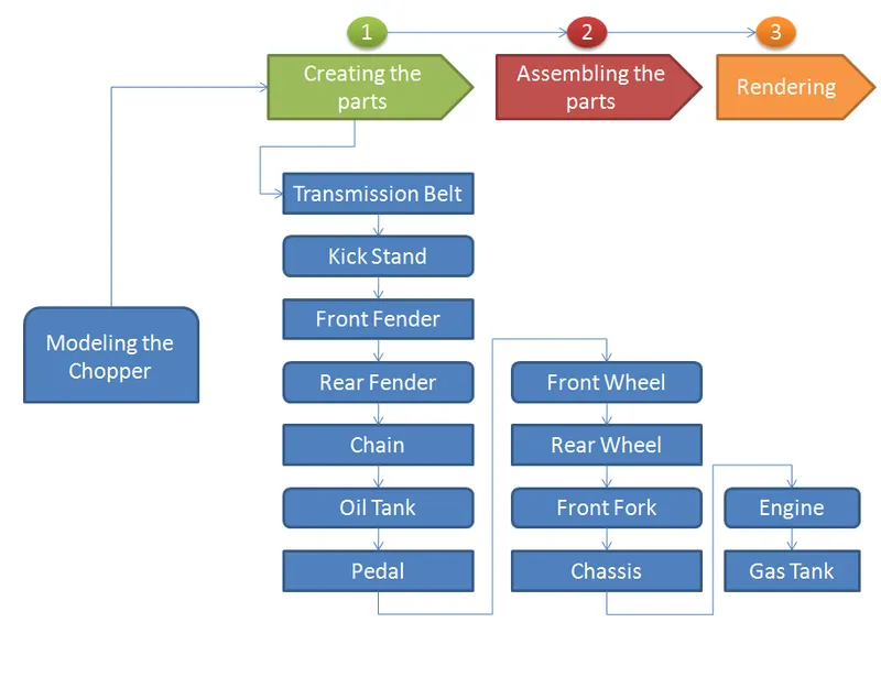
Fig. Design Methodology of the Chopper.
The features and properties given inside the SOLIDWORKS Software makes it easier to compose a 3D Object from a 2D Sketch.
Let’s have a look into the features which is used in the process of modeling the entire model of the chopper:
1.Extruded Boss/Base.
2.Fillet.
3.Lofted Boss/Base.
4.Extrude Cut.
5.Split.
6.Shell
7.Revolve Boss/Base.
8.Linear Pattern.
9.Combine.
10.Dome.
11.Mirror.
12.Projected Curve.
13.Reference Geometry.
14.Mate.
Extruded Boss/Base:
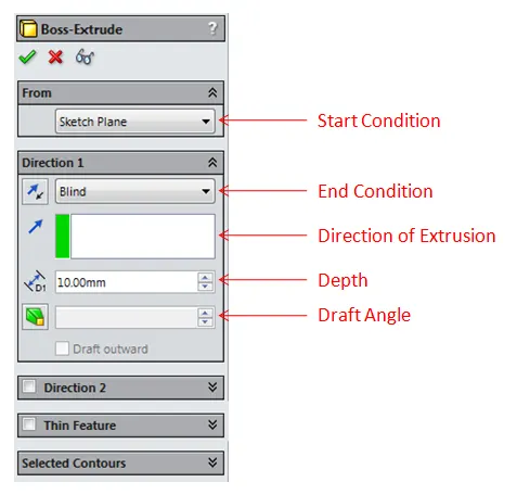
The Extruded Boss/Base feature extrudes a sketch or selected sketch contours in one or two direction to create a solid feature. It is the feature used after a sketch. To extrude an object, sketch the object geometry in two dimension sketch. Make proper dimension and relation to that geometry and then click the Extrude Boss/Base from Feature tab. It extrudes the geometry into an object with the options like Blind which uses the direction and depth. And there are so many ways to extrude that object with the options like From Surface/Face/Plane, Vertex and Offset which dropdowns from the From Option in Boss-Extrude. Sketch plane and blind are the default options present in the Boss-Extrude. You modify the Options in “From” and Direction1, Direction2. etc., to obtain required type and shape of the extrude.
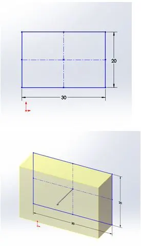
We can modify Start Condition, End Condition, Direction of Extrusion, Depth, Draft Angle to get different type of Extrudes for a geometry.
Fillet:
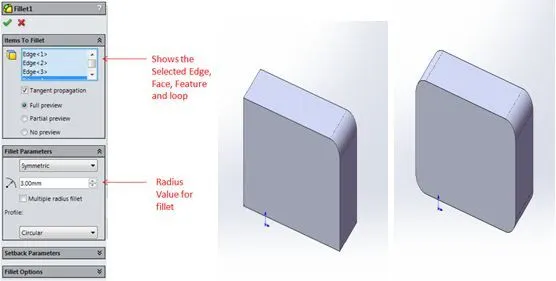
Fillet feature creates a rounded internal and external face along one or more edges in solid or surface feature. It is used to fine the edges in the model with the radius value. We can fillet the edges, face, feature and loops by selecting the appropriate item which is displayed in “Item to fillet” selection box.
Lofted Boss/Base:
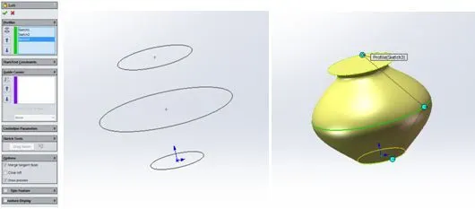
Lofted Boss/Base feature adds material between two or more profiles to create a solid feature. Lofted Boss/Base uses multiple Profiles and Guide curves to make a loft in respective to the geometry. It is very helpful tool to create complex surfaces in the model.
Extrude Cut:
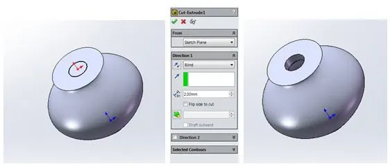
Extrude Cut feature cuts a solid model by extruding a sketched profile in one or two dimensions. This feature extrude cut the object with the options like From Surface/Face/Plane, Vertex and Offset which dropdowns from the From Option in Cut-Extrude which is similar to that in Extrude boss feature.
Split:
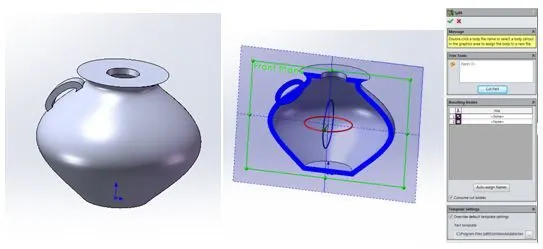
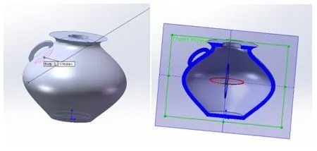
The Split feature is an extremely useful tool when designing using multibody part techniques in Solidworks. Split feature cuts out the unwanted body/part from the design as per our requirements. Split feature works with surfaces/solids. You can have the cut removal of the selected bodies even as optional using consume cut bodies check box. Split feature modifies bodies and even create new bodies by splitting it up when you deselect the consume cut bodies check box.
Shell:
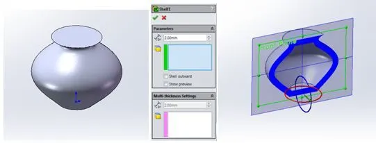
Shell feature removes material from a solid body to create a thin walled feature. When there is an object ready in the model you can simply select the “Shell” Option and give the thickness value. It will automatically create shell inside the object. You can check it in section view as it does real quick and easier.
Revolved Boss/Base:
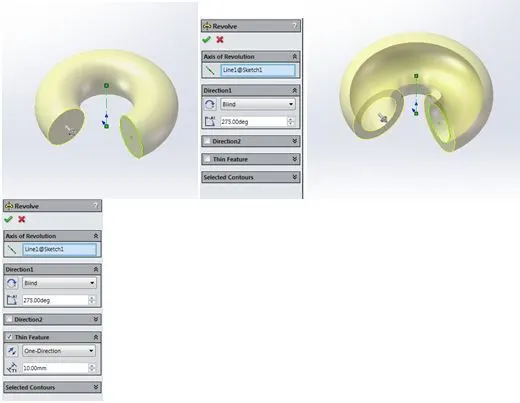
Revolved Boss/Base feature revolves a sketch or selected sketch contours around an axis to create a solid feature. Revolved Boss features are very useful in creating wheel, hub and some revolve objects. You can create two types of revolve in a single sketch, by selecting the thin feature option you can revolve the object like an offset from your sketch. When you deselect the thin feature, it gives a full contour revolve of your sketch.
Linear Pattern:
Linear Pattern feature patterns features, faces and bodies in one or two linear directions at required instances.
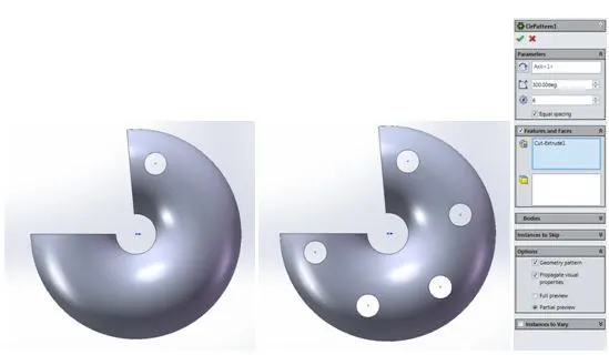
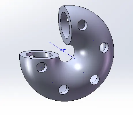
Under Linear Pattern feature there several types of patterning features such as Circular Pattern, Curve driven pattern and Sketch Driven pattern .etc,. We can turn on View temporary axis to get a quick patterning of bodies, sketches and features without having to sketch a separate construction geometry.
Combine:
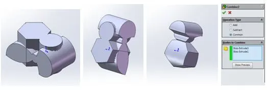
Combine feature combines two or more solid bodies. There are three different ways to use Combine; You can add, subtract, and find the common area of two different bodies. You will need multi-body part for this feature. The Combine feature lives under “Insert > Features > Combine”.
Dome:
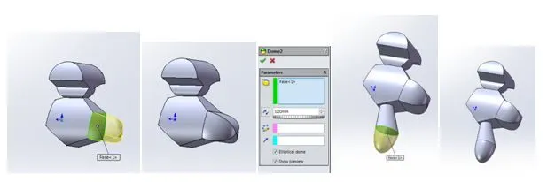
Dome feature adds one or more domes to selected planar or non-planar faces. In dome feature you can add elliptical or continous surface dome to the surface or face of the model. You can add Domes by navigate through the “Insert> Features> Dome”. Select the appropriate face/surface in which you have to make a Dome.
Mirror:
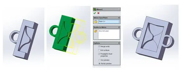
Mirror feature mirrors features, faces, and bodies about a face or a plane. By selecting a face/Plane you can mirror the object which will create a perfect opposite mirror copy of the original object. You can merge the bodies which is mirrored selecting the “Merge result” check box or else through combine feature.
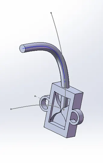
Project Curve:
Project Curve feature projects a sketch curve onto a face or sketch. It is a tool used to form 3D curves from two 2D curves from two different planes. It is used to take two sketches and then project it onto a surface. For curved object modeling it gives a easy way to determine the sketches in three dimensional form. Because a curved object will have a different angle and different geometry while viewing from different planes. This tool sort out those things by taking two sketches of a same object from two different planes and gives a projected curve, which is the 3d curve of the object or geometry.
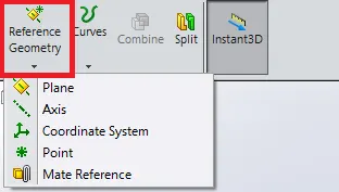
Reference Geometry:
Reference Geometry feature commands are used to create a plane, axis and points etc,. to make a reference for geometry creations. Reference geometry includes reference planes, axis, coordinate systems, and points. The Reference geometry command lives on the Features toolbar, but you can also acces it from “Insert > Reference Geometry.
When the complexity of designs increases, it often becomes necessary to create and utilize reference geometry to produce models with appropriate design intent. By creating planes you can create geometry over that planes in order to create features like lofts and sweeps.
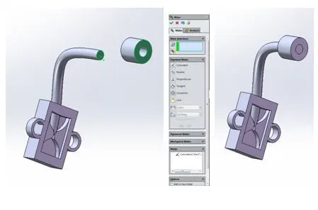
Mate:
Mate assembly tool helps us to position two components relative to one another.
Once you have created the parts for the assembly, insert that part as components in New Assembly file (i.e. through dragging and dropping, or by “Insert components” tools in Assembly tool bar. One of the great benefits of Solidworks is that there are multiple ways to accomplish the same result and that also goes for mating.
You can use the “Mates Menu”, Quick Mates and Smart Mates to get the same result of mating.
Mates Menu can be find in Assembly Menu, on the Command Manager.
You can do Quick Mates, simply by holding down the Ctrl Key and select the two entities you wish to make
To create a Smart Mate, hold down the Alt Key, and left Click and drag the circular edge to the edge you want to mate it to.
As we have gathered basic knowledge about the features in Solidworks, let us put this in modeling American Chopper in Solidworks.
Now we are going to see each part associated with the American Chopper and its design process alongside.
Each design comprises of three major steps:
- Sketching a 2D Geometry with proper dimensions and relations.
- Applying features as required.
- Applying appearances to convey the nature and the properties of the solids accordingly.
Transmission Belt:
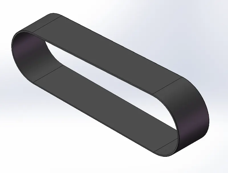
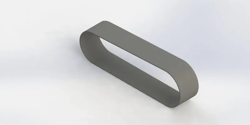
Transmission Belt is fully designed in single sketch with lines and circles. And then made offset by using offset entities sketch tool with the reference of the single sketch and extruded. To add some details to this solid body we add some fillet around the edges and set the appearance of the Belt as Matte Rubber from Rubber folder in Appearances.
Kick Stand:
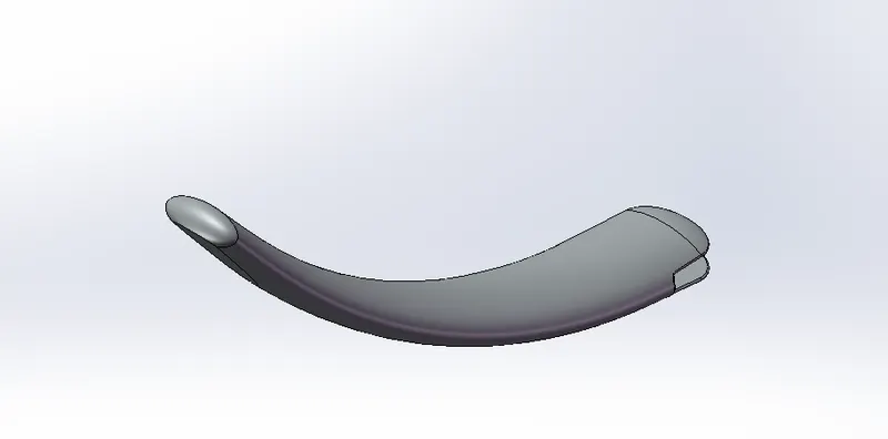
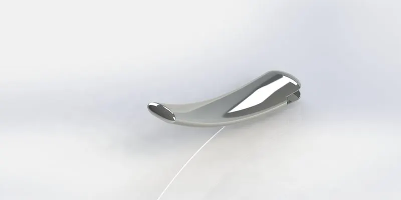
In designing the kick stand, we add more features like lofts and dome. We also used sketch tools like splines, ellipse. In addition we used a plane rather than Front, Top & Right plane. (i.e., a reference plane from reference geometry in reference of the spline and the upper end point of the spline).
On comparing with transmission Belt design, we used some advanced sketch tools like splines and features like loft, extrude cut and split.
In this model we used split tool to get flat face on the bottom of the kick stand which meets the ground surface. To add some details we gave a “Chromium plate” Appearance to the kick stand from Metal folder in Appearance tool.
Front Fender and Rear Fender:
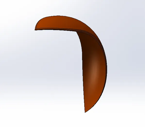
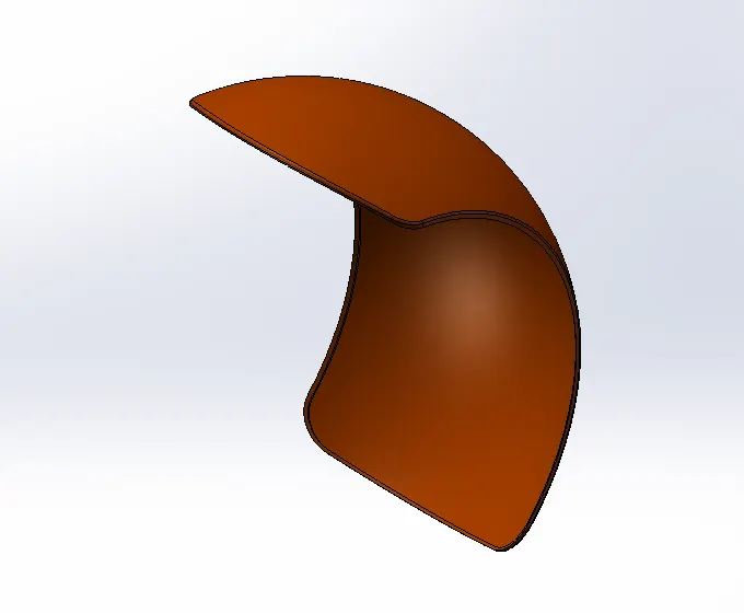
Front fender and rear fender are designed with simple sketch, but the thing we have to get notice is that we used split feature to cut off some part in the body of the fender to get a nice sharp edges on front fender and a round smooth edges on rear fender. Split feature basically used to obtain a split cut/removal of excess and bodies from our part as we used here to remove excessive bodies from fenders. Revolve boss/base feature mainly used to form the body of the fenders from a 2D sketch in reference to the axis line going along the origin. We added the shell feature for rear fender to get a good inner face hollow cut. In Appearances to get a bright look for fenders we added “Painted > Siena” appearance from Car subfolder in Appearance.
Oil Tank:
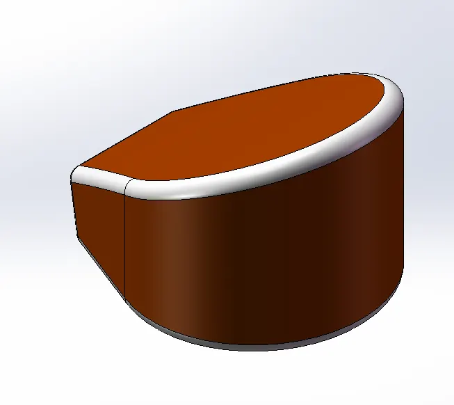
In Oil tank designing combine feature is used to get a good solid body from two different solids. Mirror entities tool from sketch entities toolbar gives a mirror of the oil tank sketch. Extrude and shell feature turn these sketches into a solid body as the extrude features gives extrude and then combining those bodies with Combine feature. Finally we used Shell feature which gives a hollow space inside the model with an offset from the solid body’s outer surface. We tried special appearances by giving a different color to filleted edges and remaining parts with Painted>Car>Siena Appearance.
Chain:
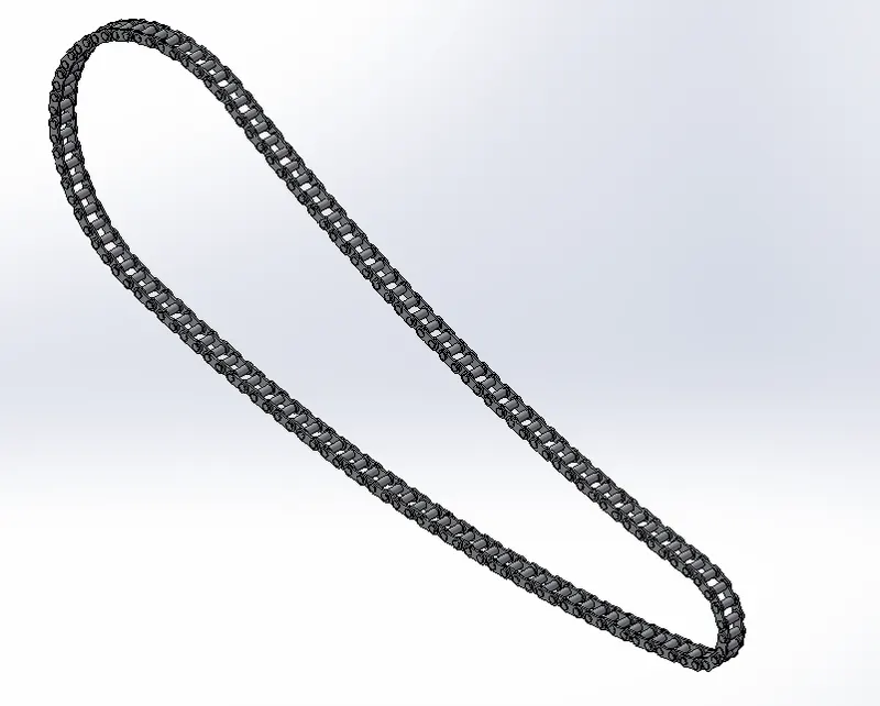
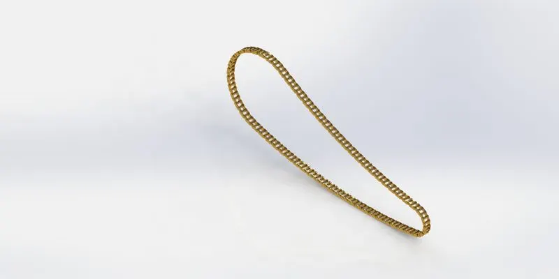
Modeling a chain part involves a simple procedure of sketching a chain plates geometry and then making those sketches into sketch blocks to use often in getting complete model of the chain. We add a primary geometry in which the chain links, chain plates and connecting plates are going to travel (i.e., Patterning of the chain plates as real as connected to the sprockets.)
Linear Pattern feature plays a major role in designing the chain model. We used circular pattern which uses a circular path to make instances of the chain links, chain plates and connecting plates. We add a little bit detail with Metal Chrome appearance.
Pedal:
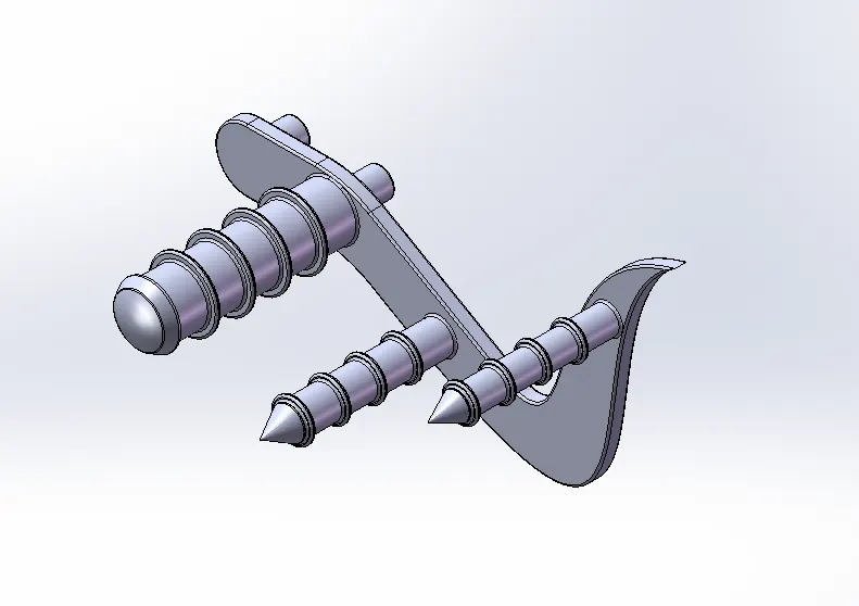
Now in this part, the initial sketch is going to be the base of our entire part so we start the sketch by adding some construction geometry which coincides with the origin. Starting with resting end of the pedal upto the sharp edge design, we used lines, splines and circles to get the geometry properly. We added extrudes, fillets, dome and chamfer features from Feature tab to design the pedal as a solid body. Linear pattern feature is used in arranging the front and rear cylindrical extruded parts from a single part and patterning it from the ends at an angle to get instance of that parts.
Front and Rear Wheel:
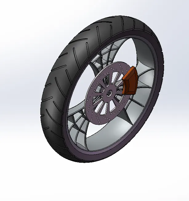
Starting a base sketch of hub and rim from the front plane makes the wheel part properly constructed. Revolving those parts using Revolve Boss/Base feature from Feature tab provides the solid body of the rim and hub. Then we started sketch on the right plane for spokes and extrude in relation to the mid plane. For adding a spider web design in the spokes we used convert entities, offset entities, 3 point arcs from sketch toolbar. To give a nice design we started sketching on the front plane and used Revolve cut feature to make a revolved cut along the hub and the rim parts.
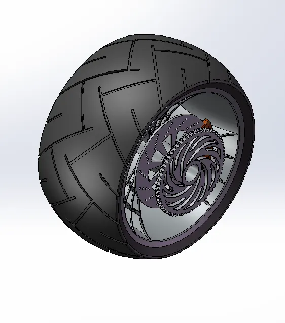
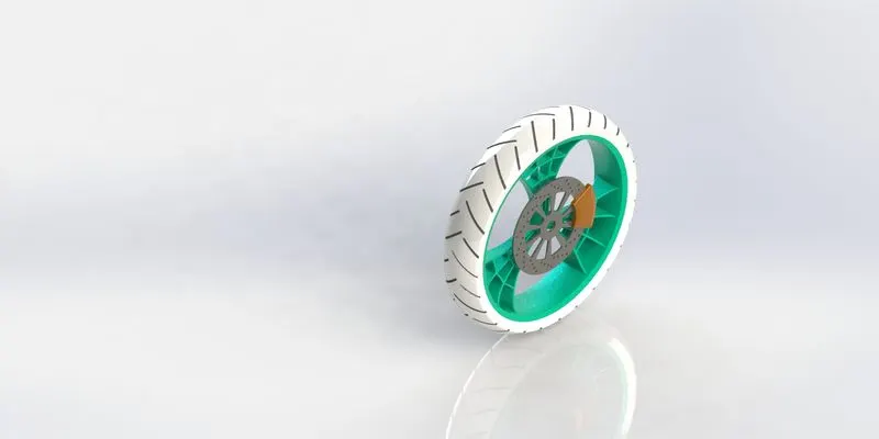
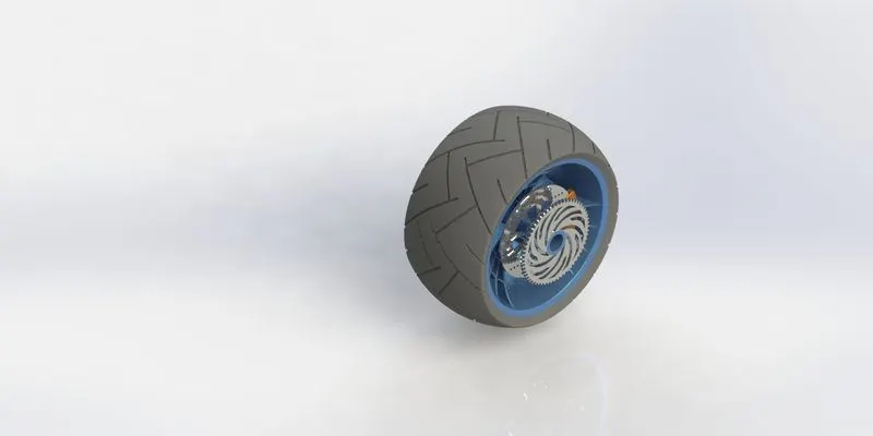
Then we started a sketch for the geometry of tire from the front plane and revolved it using Revolve Boss/Base feature. For some nice treads on the outer surface of the tire we started sketching on the front plane with 3 point centre rectangle sketch tool and made an extrude cut from an offset from the surface of the tire. We used fillets in spokes, hubs and treads in tire to get a round filleted edges. Rotor is designed from the right plane with circles, line sketch for base and cut parts. Linear patterning the cut extrude parts inside the rotor give a nice design for it. Then we designed caliper with circles and added chamfer feature on the both faces of the caliper.
Front and Rear wheels are constructed in the same set of above process. But only for Rear wheel we add sprocket geometry with the help of circles, extrude cut feature and linear patterning features. Then, Wheel axle geometry is made with sketches and revolved and then connected to the rear sprocket and Wheel. After creating all these parts, from solid bodies we renamed each solid bodies of the wheel and then added separate appearance to the bodies by extending the feature tree display pane and selecting the appearance icon with respect to solid body.
Front Fork:
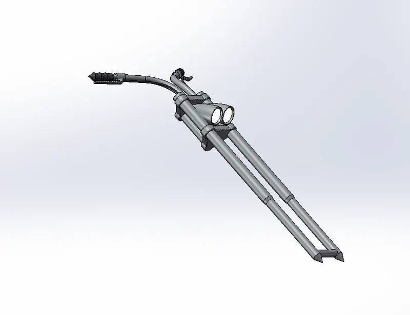
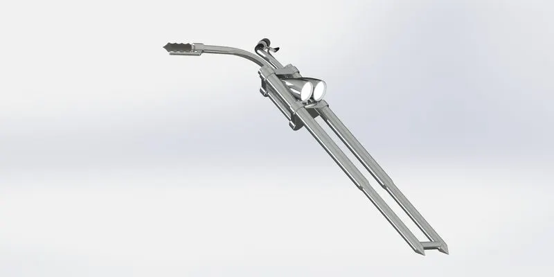
It seems like it is a complicated part to design, but we do all those parts like handle bar, fork, triple clamp, headlight, brake lever, brake wire and grip one by one starting from a 2D sketch for fork. With fork face as sketch plane, we can start sketching the triple clamp. For parts like this we can sketch and form a solid body which is half of the whole body and we can use mirror feature produce complete from these half parts. It’s the good way handle complex sketches like by focusing on half part of the body and then using feature like mirror complete the rest of the body.
After creating the triple clamp use linear pattern to pattern a instance along the fork. Then from the face of triple clamp sketch the geometry for the handle bar. As it is a curved object we must put one additional step of creating project curve to get a correct formation of the handle bar. Like this, we start sketching the remaining geometry of brake lever, grip and brake wire one by one from the handle bar sketch as reference. Sweep, Project curve and Extrude features are used in creating this geometry
Then we have to sketch the geometry for head light and create a revolve to obtain head light body. We can move the headlight to position it with the fork using Move/Copy Body feature from “Insert > Features” menu. Use chamfer and extrude cut features to headlight glass structure in the front face of the headlight.
Mirror the objects using “Mirror” feature from Feature tab. This simplifies the process of creating geometry for other half.
Use Combine feature to join the mirrored bodies which in real comes as single body like fork axle and triple clamps.
Apply Chromium plate appearance to fork, headlight bucket, triple clamp and brake levers. Apply Gloss rubber appearance to grips and brake wires. Finally apply Area light appearance to the headlight.
Chassis:
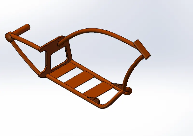
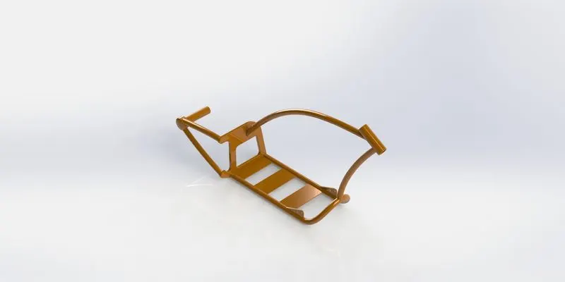
Chassis is the main frame part in all vehicles. For designing the Chassis, Start sketching the curves on two or more planes for projecting these curves into a single curve using Project Curve from Curves Feature in Feature tab. Then sweep that curve to form a tube using Swept Boss/Base feature. With reference to this tube, sketch and extrude the base frame tube. And then sketch and sweep the front tube which about to connect the fork tube. Sketch and extrude Back plate from base tube. From the face of the back plate sketch and sweep tubes which connects the main axle of rear wheel. Then sketch and sweep upper rod which holds the gas tank and supports the fork tube. For fork tube sketch a reference line at front from front plane, and sketch a rectangle and rectangle which connects with the upper and lower tubes of the Chassis.
Sketching rectangles from front plane along base tube, extrude the rest plate for engine in the chassis.
Apply Siena appearance for the whole chassis.
Engine, Motor and the Exhaust System:
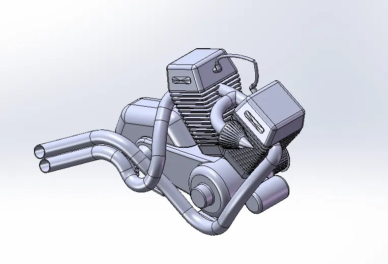
We are going to create motor, engine and exhaust system one by one and combine finally it into single part.
In motor part we use circles and extrudes to create the body and use fillets to fine the part. And we create transmission pulley along with this motor. On designing the pulleys we us extrude, extrude cut for tooth creation and linear pattern features.
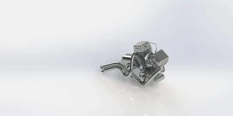
In designing the engine part fins seems like a complex geometry. But using the extrude cut and linear pattern that cut make it much easier in two steps. Chamfer feature converts the rectangular object and gives the engine design. Mirror feature is used to create another engine body from this engine body. Spark plugs are created using sweep feature.
And finally the exhaust system is made by projected curves and sweep feature.
Apply Chromium plate appearance for the whole engine parts.
Gas Tank:
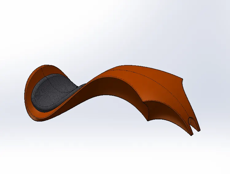
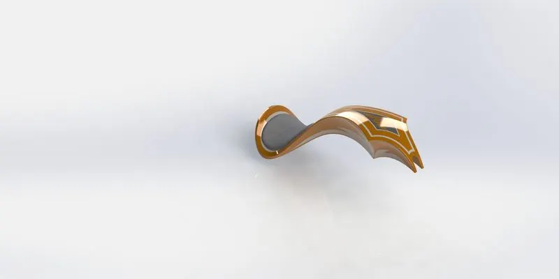
Designing the gas tank comprises of using projected curve, split line, Swept cut, fillet and Shell features from Feature tab and Swept surface, Boundary Surface, Lofted surface, Mirroring the surface, Knit surface from Surface tool bar.
Using the blue print for sketching made this geometry easy to create.
Applied Siena appearance for the gas tank and grey cotton fabric for seat surface.
Assembly:
The term mechanical assembly is most often referred to putting components together in an assembly line, but more specifically, it refers to creating a complete product that performs an intended function.
In this solid modeling we use bottom up approach, as we designed the parts individually.
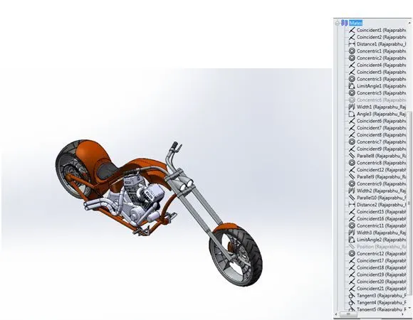
Mate is the main tool used in assembly for mating the parts together, i.e assembling the parts with correct mating relation with the parts.
We start assembly by fixing the chassis, and mating the engine, gas tank, rear wheel, front fork, front wheel, front fender and rear fender in relation to the chassis. And we also created mate with chains, sprockets and transmission belt using Advanced mate tool like width mate.
Rendering:
Rendering is the process of generating a photorealistic or non-photorealistic image from a 2D or 3D model utilizing a computer program. At present, there are multiple computer programs available to perform the rendering.
The rendering of a CAD model in Solidworks can be done by using the following software & the first two software are widely used for rendering.
- Photoview 360
- Solidworks Visualize.
- Onshape
- Keyshot
- Blender
In order to render image for the object you must create a camera view otherwise you must enable perspective view.
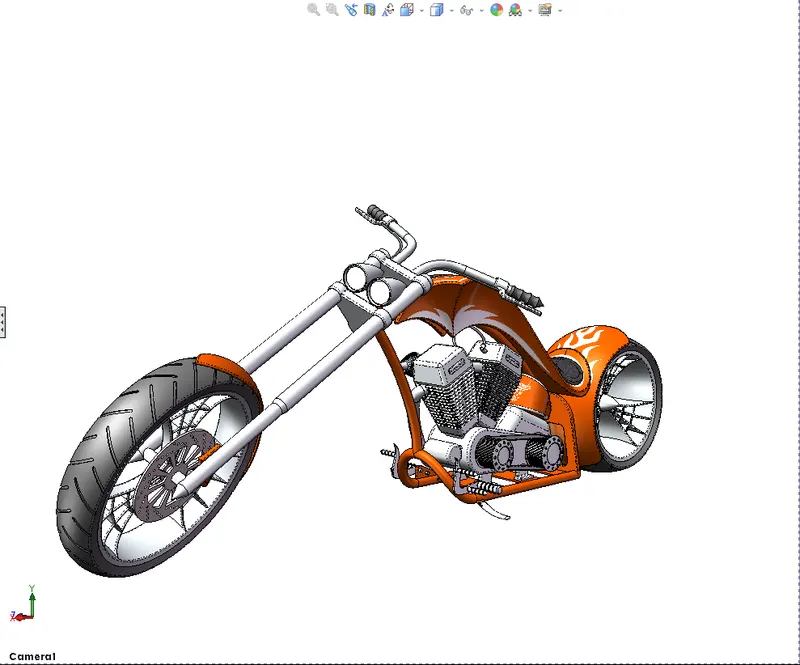
In this project, I do the renders through Photo View 360 add-in.
Photoview 360 add-in can be found in menu tab by enabling it from ”Tools > Add-in” Option.
By enabling it you can also get a Render tools tab, from there you can edit a scene, edit decals and adjust the render option to render the object.
Following are the renders of the chopper in different views and in different environments.
In each render I adjusted the lighting brightness and environment rotation.
Renders mentioned below are named after the environment or the feature or the scene which I used.
Plain White Render:
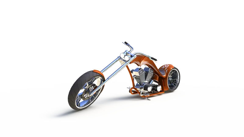
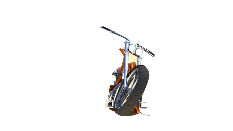
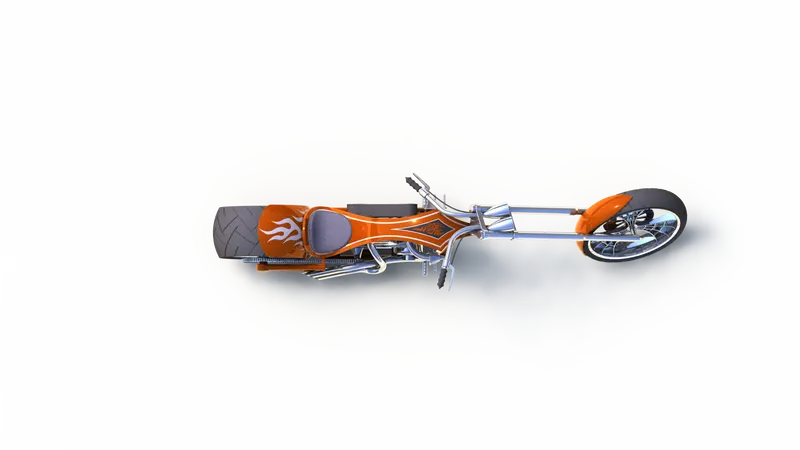
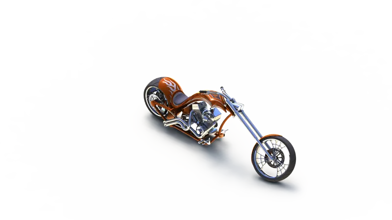
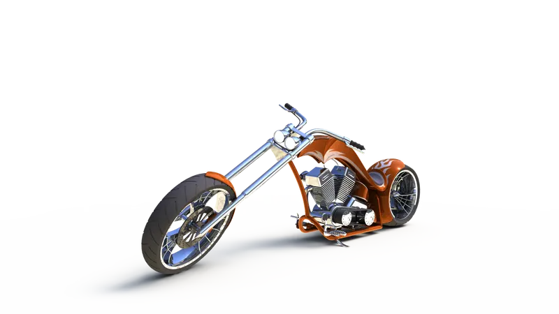
After creating the chopper, I used plain white scene and daytime environment to quickly grab the idea and visualization of the chopper. Adjusting the lighting brightness from Photoview 360 lighting tab in Edit Scene option gives a nice bright look of the chopper.
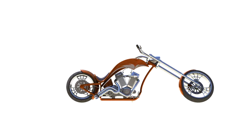
Different views of American Chopper in Plain white render:
Front View
Side View
Top View
Iseometric View
Camera View
Contour Render:
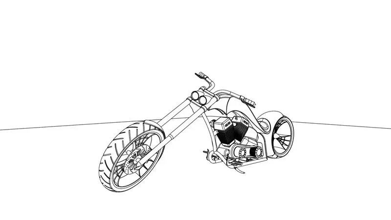
Contour rendering provides the outline of the drawing of the object by emphasizing the mass and volume of the object rather than detail. These types of rendered images are widely used in product manuals and also used while patenting a design. Contour render is made through enabling the contour render option under Photoview 360 Options. I used the plain white scene for this render in order to have a plain backgroud.
Different views of American Chopper in Contour Render:
Front View
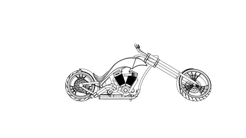
Side View
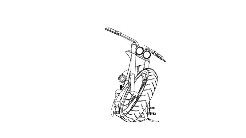
Top View
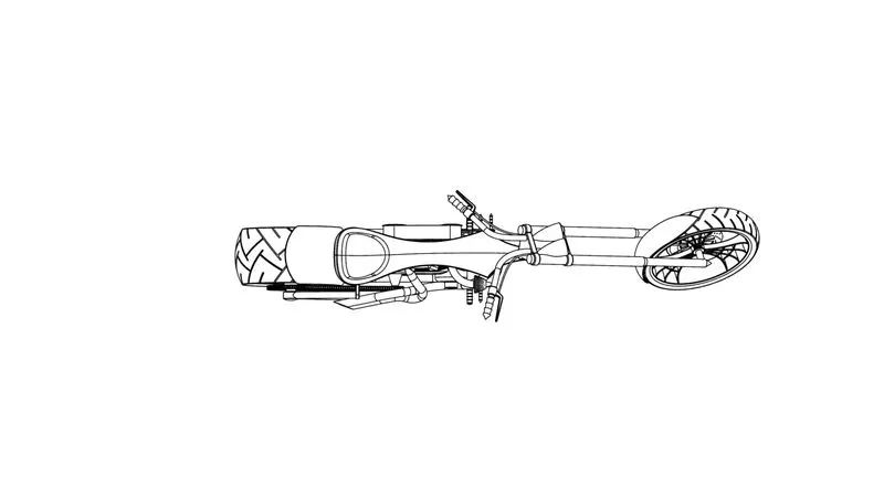
Isometric View
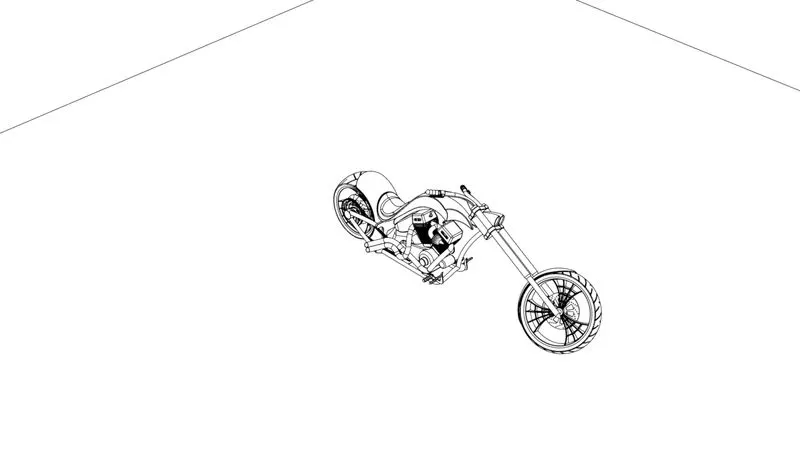
Camera View
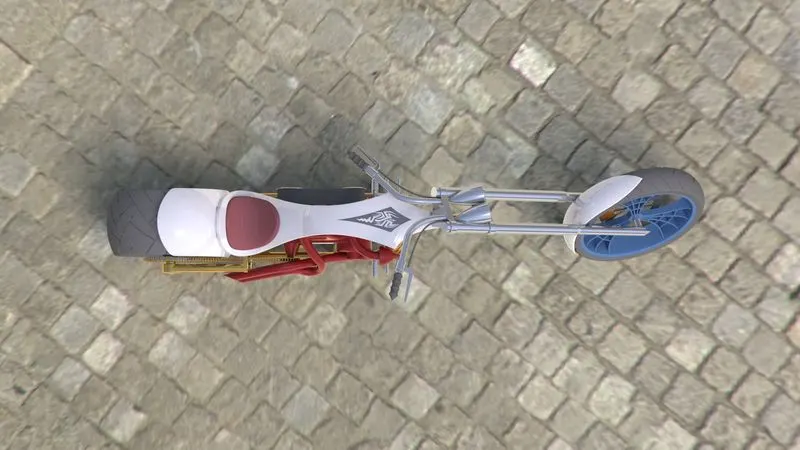
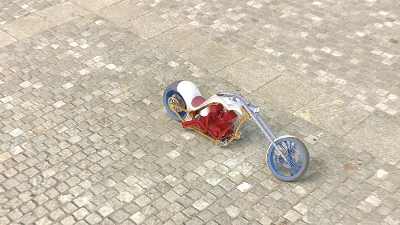
Courtyard Render:
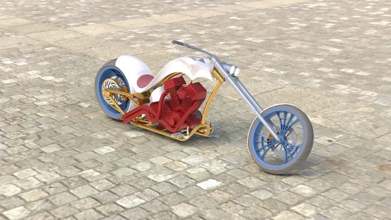
In Courtyard Render, I used courtyard background as environment and daytime scene for lighting and scenes. I adjusted lighting in Photoview 360 lighting tab with environment brightness and render brightness to set the scene. I also adjust the environment rotation in order to expose quite details in the surface of the chopper in the day time-courtyard environment.
Different views of American Chopper in Courtyard Render:
Front View
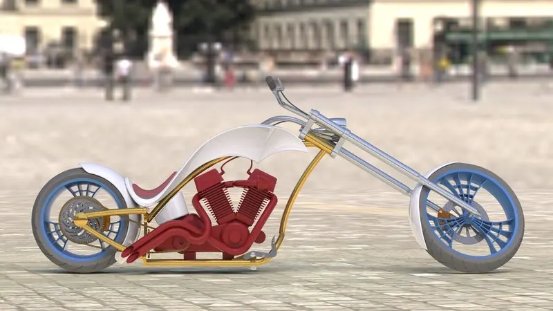
Side View
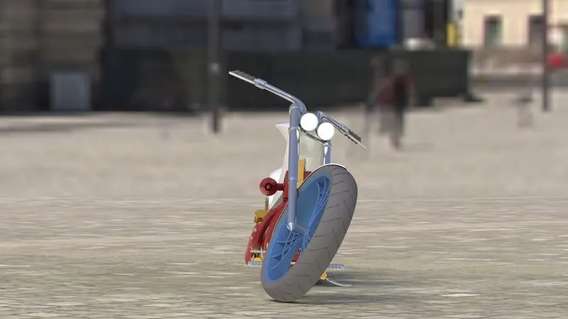
Top View
Isometric View
Camera View
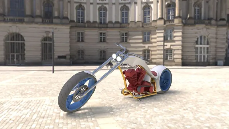
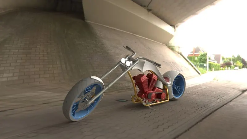
Under the Bridge Render:
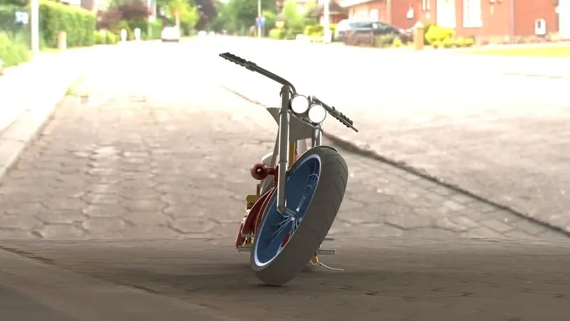
In plain white and court yard renders, I used environments and scenes which comes preloaded in Solidworks software. But in this under the bridge render I used environment and scenes of a bridge which I downloaded seperately from a solidworks forum. This Under the bridge Render gives a cool outdoor environment scene and a nice real look for the chopper.
Different views of American Chopper in Under the bridge render:
Front View
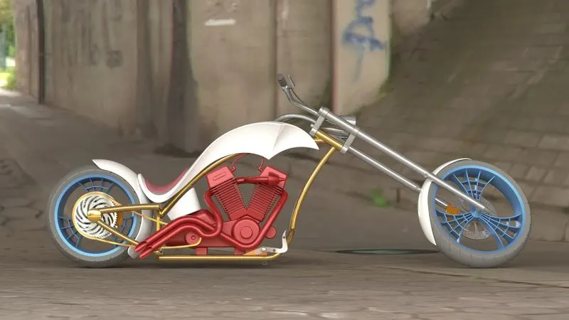
Side View
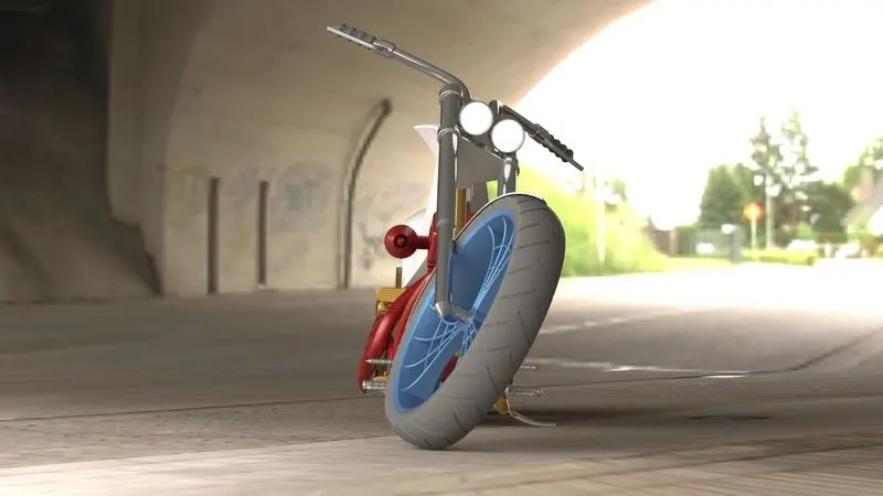
Top View
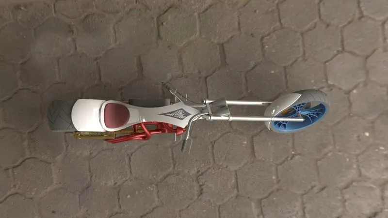
Isometric View
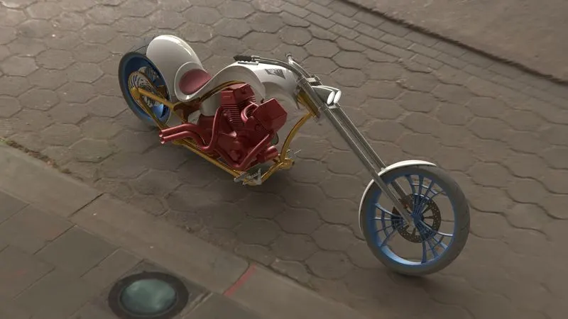
Camera View
Route 66 Render:
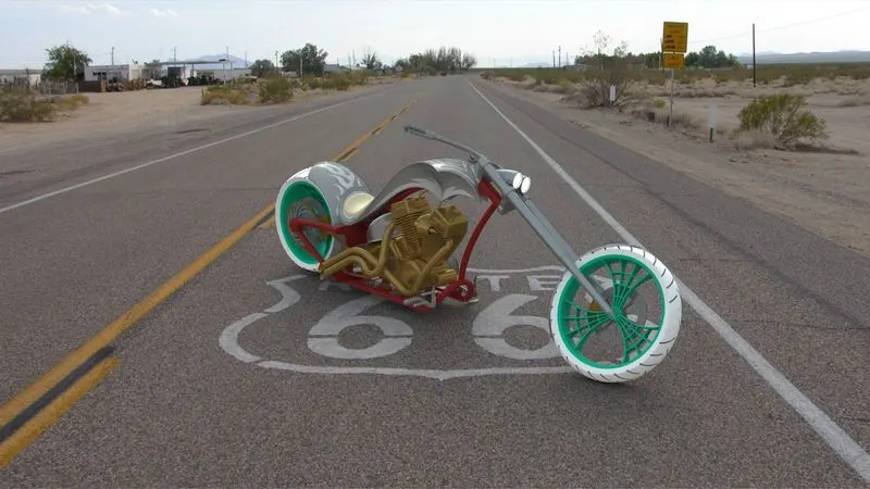
Route 66 Render is a pretty cool render with a highway background. This render files may available with preset environment in Solidworks Visualize. As I am not having the Visualize software, I downloaded this render environment and background images seperately from a solidworks forum. Because, I don’t want to miss a render view of this chopper in this nice environment scene. I adjusted the Render brightness, Environment brightness and Environment rotation to get a good view of American Chopper in this scene.
Different views of American Chopper in Route 66 Render:
Front View
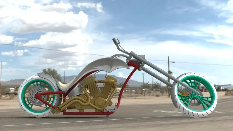
Side Views
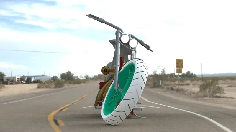
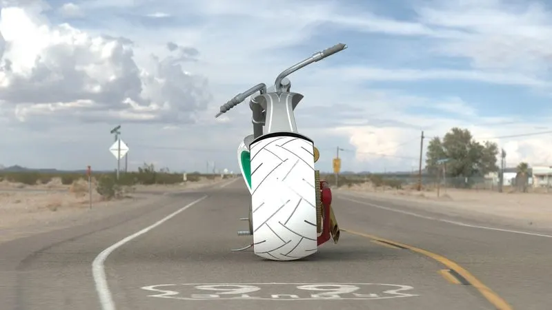
Top View
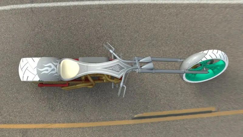
Isometric View
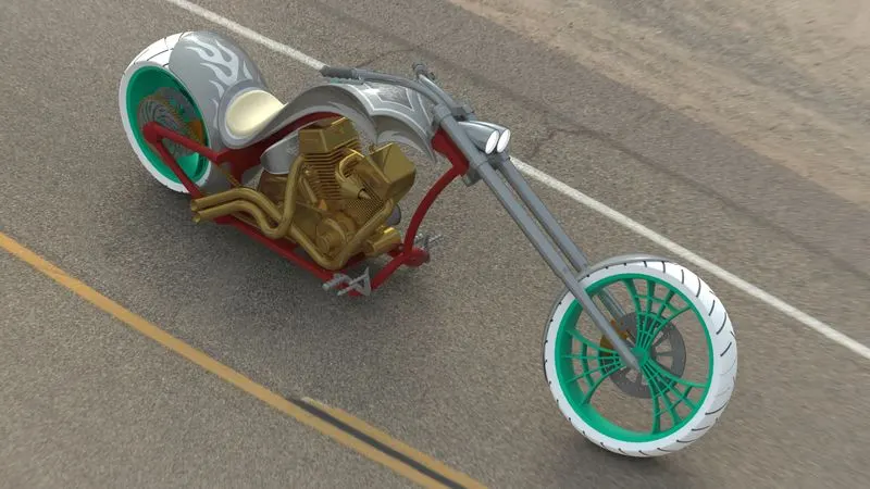
Camera View
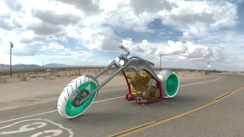
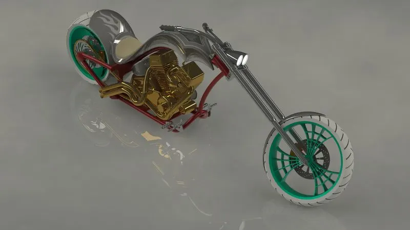
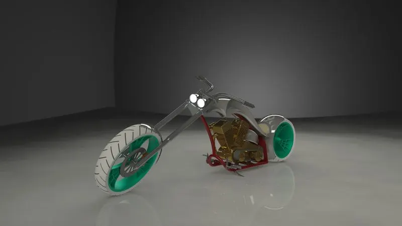
Studio Render:
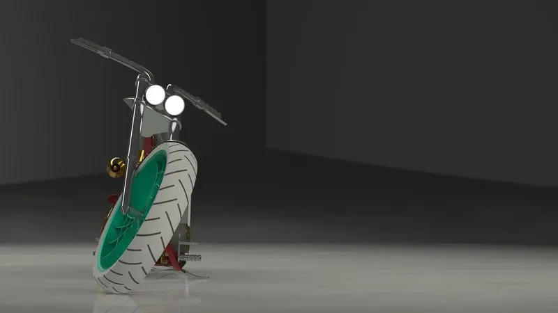
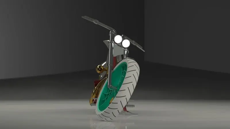
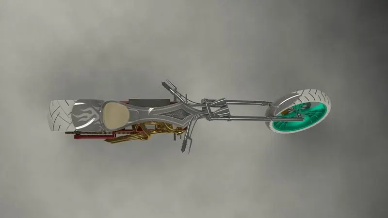
And finally I rendered the chopper in Studio render, a quality studio scene. This is an environment scene which I downloaded separately from a solidworks forum. It gives a perfect look of the chopper placed in a high quality studio environment. I adjusted the environment brightness and environment rotation to get a high quality studio render of American Chopper.
Different views of American Chopper in Studio Render:
Front View
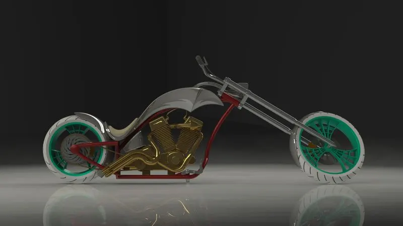
Side View
Top View
Isometric View
Camera View
On Selecting the Perfect Render Image:
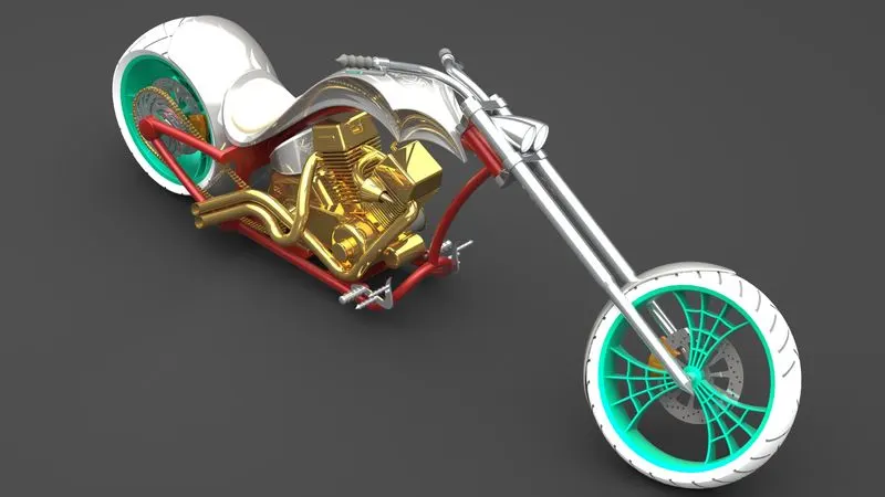
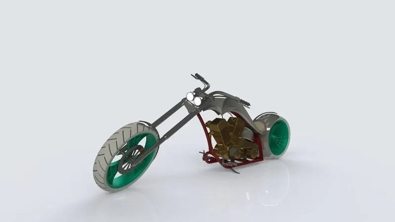
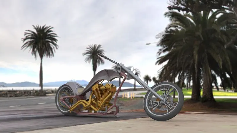
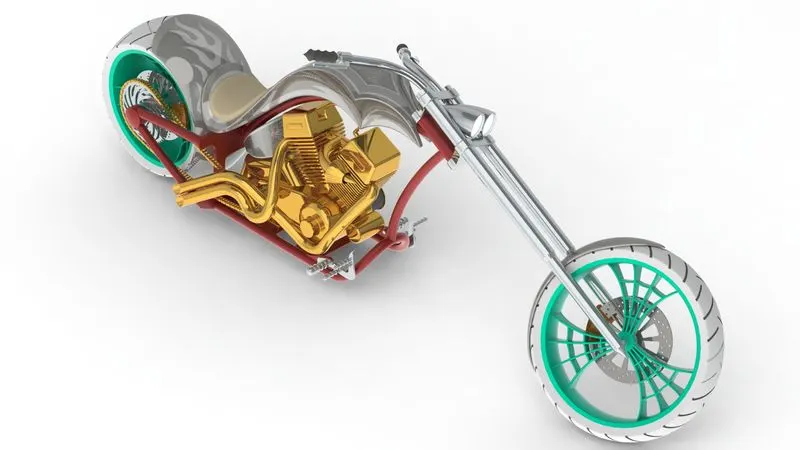
After doing some renders with different scenes and envrionment, we can get a clear idea in exposing our chopper model. Then we have to go for few more environment and scene check to give a promising product design of American Chopper, as I checked below:
1. Black Studio Environment:
2. White backdrop Studio Environment:
3. Urban Environment:
4. White Studio Environment:
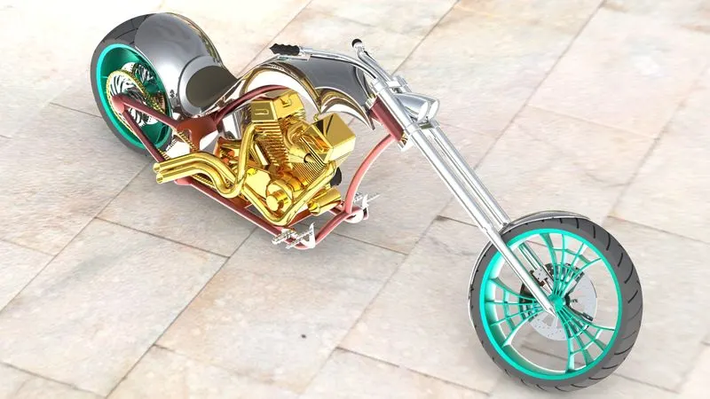
5. Swimming Pool Environment:
6. Courtyard 1 Environment:
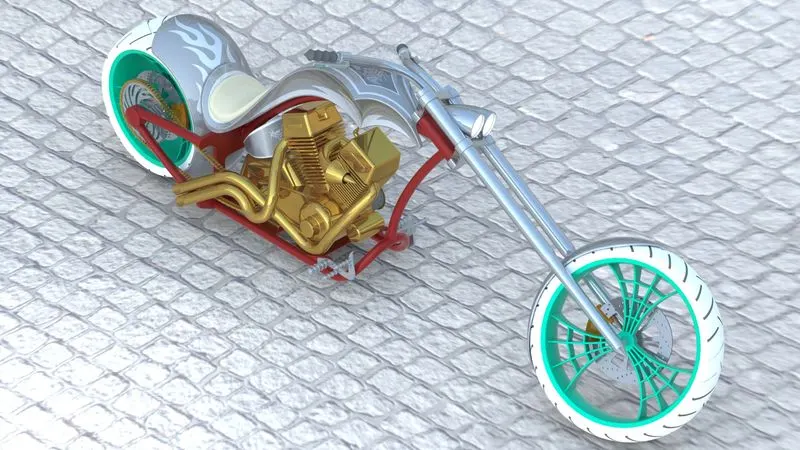
In comparing swimming pool and courtyard 1 environment, I haven’t changed the white color of tire to black in swimming pool environment image, But the fact is the swimming pool environment scenes and properties changed the white color tire to black and also gives us a nice dark shining look of the gas tank and fenders. As looking this, sometimes the environment and scene are the things which are going to decide the look of your product. So you must go through with some different environment and scenes for the perfect render image for the product.
7. Fluorescent Light Studio Scene:
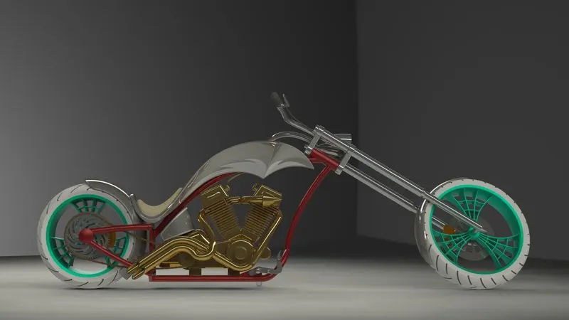
This fluorescent light studio environment gives a quite promising look of American Chopper with studio scene setup. In case of giving a product design this gives a good idea for American Chopper.
On making your product valuable in the market, you must submit a good render image for the first best impression of your product in the market.
For the best product design of American Chopper which I designed, I will go for the following image:
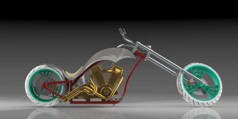
This render image gives a nice look of the product I designed. Shines and reflections over the front fork, gas tank, fenders and some dark shades in engine gives an expectation over the product, and the standard look of seat and tires gives a very good promising product design for this American Chopper.
You can do even better renders in Solidworks Visualize software. But right now I can’t place a render image from Visualize software as my computer specification doesn’t meet the minimum requirements of the Solidworks Visualize software to install.
So, I done the renderings through the Photoview 360 itself and I am satisfied with the render images that it gives.
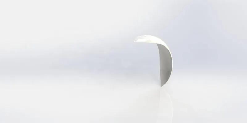
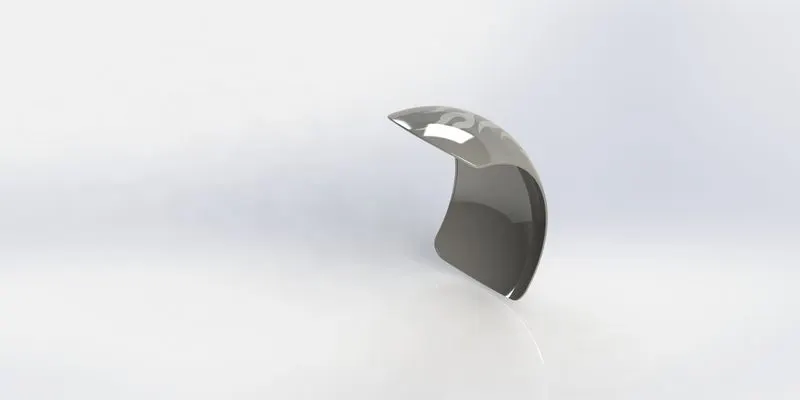
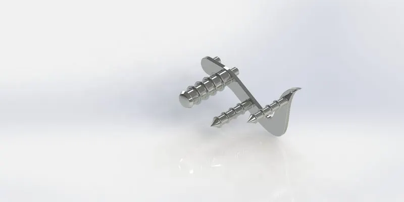
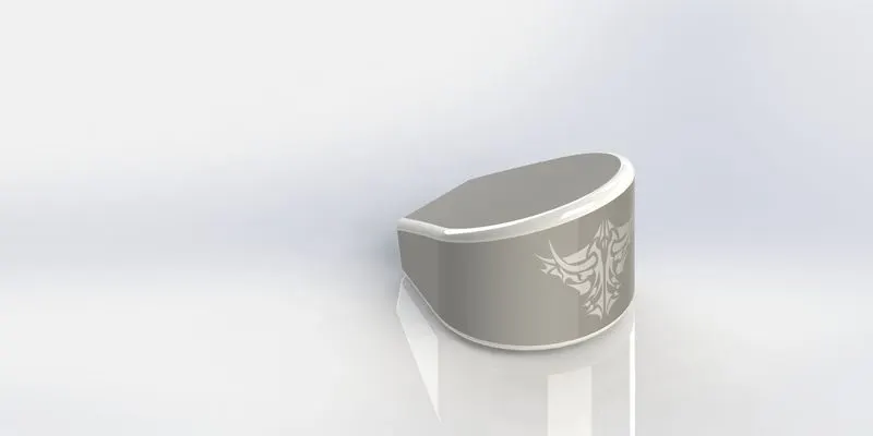
I have also placed the render images of the parts below with different looks:
Conclusion:
The American Chopper is successfully modeled in Solidworks. The parts are modeled using Sketch, features and surface tools and assembled together with assembly tools like mates. Then successfully rendered to get a good product design like render image of the American Chopper.
Project report and models are attached in the below link as a zip file:
https://drive.google.com/file/d/1-diTIH5fCqJISi6-Hn6LVoj77FrDb772/view?usp=sharing