FINAL INDEPENDENT PROJECT
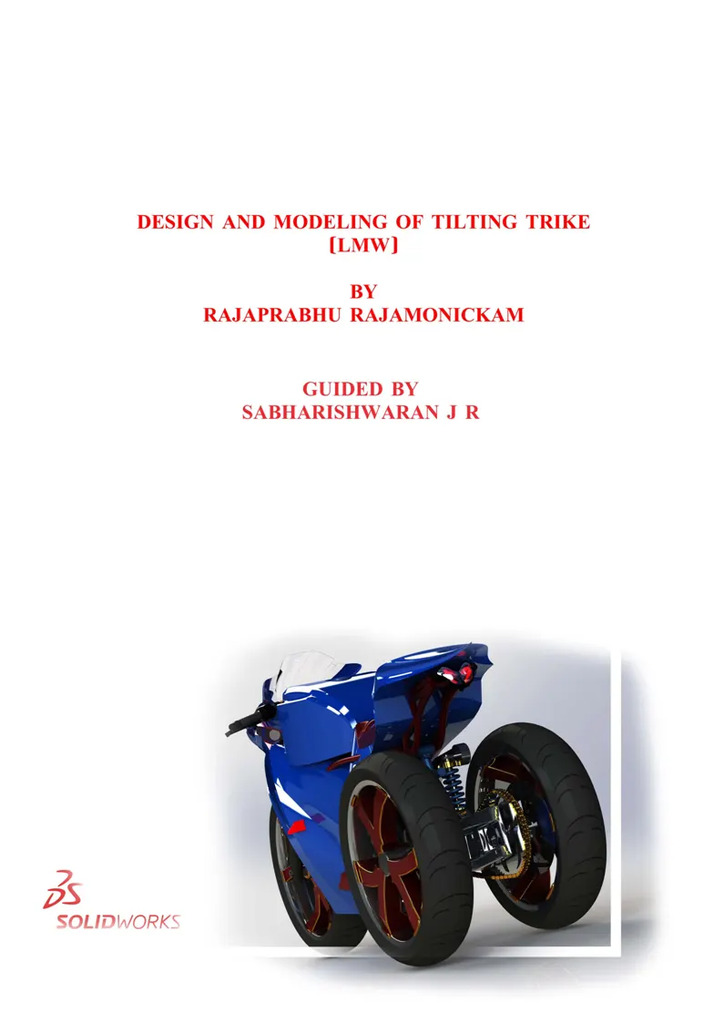
DESIGN AND MODELING OF TILTING TRIKE(LMW).
OBJECTIVE:
To design and model a concept design of tilting trike with Leaning Multi-Wheel mechanism using Solidworks CAD software and rendering it to visualize as a realistic object.
ABSTRACT:
The safety of the passenger is the first and most important thing to be considered in vehicles.
Tilting mechanism increases the maximum speed in curves.
The use of tilting mechanism in automobile would decrease the rate of accidents due to slippage and roll over of the vehicle.
It will give better dynamic stability as well as directional stability to the vehicle, road grip and better comfort to the passengers.
Leaning Multi‑Wheel technology delivers a high feeling of stability when cornering on various road surfaces.
INTRODUCTION:
A three wheeled vehicle, also known as a trike. Having one wheel in front and two wheels in rear or one wheel at rear and two wheels at front. Tilting trikes are of two types:
1.Delta type,
2.Tadpole type.
If the motorcycle contains two wheels at rear and one wheel at front, then it is delta type trike.
If the motorcycle contains two wheels at front and one wheel at rear, then it is tadpole type trike.

Fig. Delta Type Trike
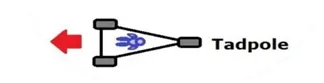
Fig. Tadpole Type Trike
In this project a delta type trike is going to be designed.
This project is inspired by the news from piaggio’s latest patent update on trikes. And then Yamaha’s scope on leaning trikes in future and kawasaki’s four wheel leaning vehicle concepts.
As the leading motor cycle companies step into producing the motorcycles more than two wheels, this project is the one along this way.
But the main motive of this project came from my self-experience, as I met with an accident in 2016 and when I just escaped at last second with few wounds while I am seating behind and my friend got struck with the motorcycle and wounded more, I have the thought to reduce these types of accidents. One thing that caused this accident is that he can’t control the vehicle quickly at that moment. The main thing is we all put a sudden control or force on the front wheel and the rear wheel got slips out and when we have a little time to sense and control the rear wheel we just escape from thisslippage.
SCOPE OF PROJECT:
During cornering the forces acting to roll the vehicle out of a corner are balanced by the leaning mechanism.
This leaning mechanism at rear wheels also gives a feel of riding sports bike and at the same time it gives a full comfort of safety driving.
I named this trike as “ hagana’ “ after a Hebrew word for protection, defense etc. As this trike is fully designed to give safety in riding and as well as a belief of safety riding in the minds of the riders.
SPECIFICATIONS:
The leaning angle will be from 30 – 32 degree.
A frame and two suspensions are attached to the rear wheel frame.
The linkages are quite similar to parallelogram linkages.
HOW THIS DESIGN DEFERS FROM THE DESIGNS AVAILABLE IN MARKET:
- Two wheels at rear side which provides leaning mechanism.
- Two separate suspensions for both rear wheels.
- Separate frame for the rear wheels and suspensions. This frame is connected with the main frame.
- As two wheels comes at rear end it gives real feel of a big rear wheel experience for the rider
MODELING:
A Model is a mathematical representation of a geometric form, which is stored in the computer memory. 2D Models are recognized by the system as flat frameworks bounded by a numberpoints, which are defined by X and Y Cartesian coordinates. A 3D Model may be held in computer memory by specifying points with a third Z coordinate.
Viewing an object in 3 dimensions helpsto get a sense of its true shape and form. It also helps in design, which in turn allows us to make better design decisions. It helps to communicate our ideas to those who may not be familiar with the orthographic views including sections and side views of design.
In this project the entire modeling of a Tilting Trike is carried out in SOLIDWORKS CAD Software.
Solidworks contains the capabilities to produce 3D Models. These capabilities are used interactively with 2D drawings.
The different components of the trike we deal with are:
- Connecting Arm and Swing Arm.
- Linkages
- Wheels
- Frame
- Main fairing
- Tail, front fairing, seat, fuel tank and windshield
- Engine
- Some other trike parts.
After designing the part components, I worked the assembly and the Photo rendering of the trike which gives the model a complete and realistic view.
DESIGN METHODOLOGY:
Design methodology of the trike model is described step by step in the following flow chart:
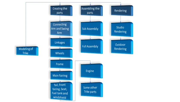
Fig. Design Methodology of the Trike.
The features and properties given inside the SOLIDWORKS Software makes it easier to compose a 3D Object from a 2D Sketch.
Let’s have a look into the features which is used in the process of modeling the entire model of the trike:
1.Extruded Boss/Base.
2.Fillet.
3.Lofted Boss/Base.
4.Extrude Cut.
5.Split.
6.Shell.
7.Revolve Boss/Base.
8.Linear Pattern.
9.Combine.
10.Dome.
11.Mirror.
12.Projected Curve.
13.Reference Geometry.
14.Surface tools.
Extruded Boss/Base:
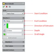
The Extruded Boss/Base feature extrudes a sketch or selected sketch contours in one or two direction to create a solid feature. It is the feature used after a sketch. To extrude an object, sketch the object geometry in two dimension sketch. Make proper dimension and relation to that geometry and then click the Extrude Boss/Base from Feature tab. It extrudes the geometry into an object with the options like Blind which uses the direction and depth. And there are so many ways to extrude that object with the options like From Surface/Face/Plane, Vertex and Offset which dropdowns from the From Option in Boss-Extrude. Sketch plane and blind are the default options present in the Boss-Extrude. You modify the Options in “From” and Direction1, Direction2. etc., to obtain required type and shape of the extrude.
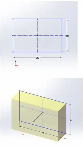
We can modify Start Condition, End Condition, Direction of Extrusion, Depth, Draft Angle to get different type of Extrudes for a geometry.
Fillet:
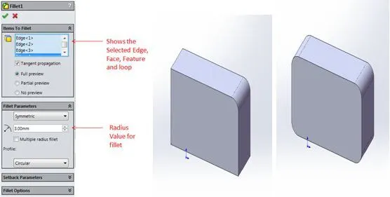
Fillet feature creates a rounded internal and external face along one or more edges in solid or surface feature. It is used to fine the edges in the model with the radius value. We can fillet the edges, face, feature and loops by selecting the appropriate item which is displayed in “Item to fillet” selection box.
Lofted Boss/Base:
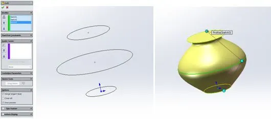
Lofted Boss/Base feature adds material between two or more profiles to create a solid feature. Lofted Boss/Base uses multiple Profiles and Guide curves to make a loft in respective to the geometry. It is very helpful tool to create complex surfaces in the model.
Extrude Cut:
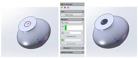
Extrude Cut feature cuts a solid model by extruding a sketched profile in one or two dimensions. This feature extrude cut the object with the options like From Surface/Face/Plane, Vertex and Offset which dropdowns from the From Option in Cut-Extrude which is similar to that in Extrude boss feature.
Split:
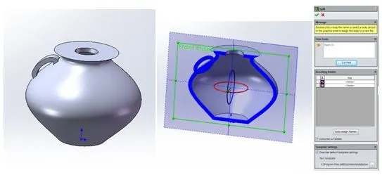
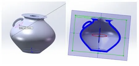
The Split feature is an extremely useful tool when designing using multibody part techniques in Solidworks. Split feature cuts out the unwanted body/part from the design as per our requirements. Split feature works with surfaces/solids. You can have the cut removal of the selected bodies even as optional using consume cut bodies check box. Split feature modifies bodies and even create new bodies by splitting it up when you deselect the consume cut bodies check box.
Shell:
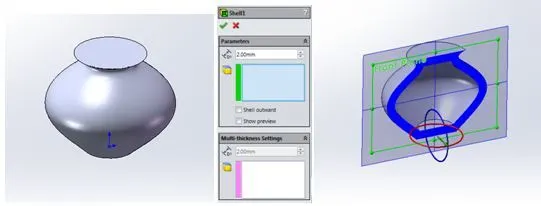
Shell feature removes material from a solid body to create a thin walled feature. When there is an object ready in the model you can simply select the “Shell” Option and give the thickness value. It will automatically create shell inside the object. You can check it in section view as it does real quick and easier.
Revolved Boss/Base:
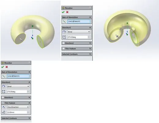
Revolved Boss/Base feature revolves a sketch or selected sketch contours around an axis to create a solid feature. Revolved Boss features are very useful in creating wheel, hub and some revolve objects. You can create two types of revolve in a single sketch, by selecting the thin feature option you can revolve the object like an offset from your sketch. When you deselect the thin feature, it gives a full contour revolve of your sketch.
Linear Pattern:
Linear Pattern feature patterns features, faces and bodies in one or two linear directions at required instances.
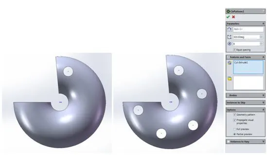
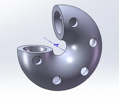
Under Linear Pattern feature there several types of patterning features such as Circular Pattern, Curve driven pattern and Sketch Driven pattern .etc,. We can turn on View temporary axis to get a quick patterning of bodies, sketches and features without having to sketch a separate construction geometry.
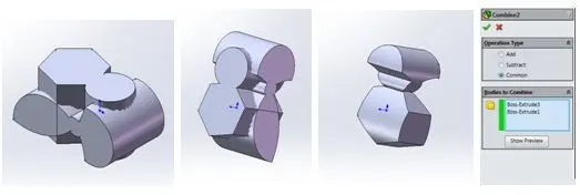
Combine:
Combine feature combines two or more solid bodies.There are three different ways to use Combine; You can add, subtract, and find the common area of two different bodies. You will need multi-body part for this feature. The Combine feature lives under “Insert > Features > Combine”.
Dome:
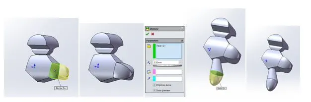
Dome feature adds one or more domes to selected planar or non-planar faces.In dome feature you can add elliptical or continous surface dome to the surface or face of the model. You can add Domes by navigate through the “Insert> Features> Dome”. Select the appropriate face/surface in which you have to make a Dome.
Mirror:
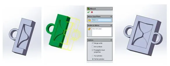
Mirror feature mirrors features, faces, and bodies about a face or a plane. By selecting a face/Plane you can mirror the object which will create a perfect opposite mirror copy of the original object. You can merge the bodies which is mirrored selecting the “Merge result” check box or else through combine feature.
Project Curve:
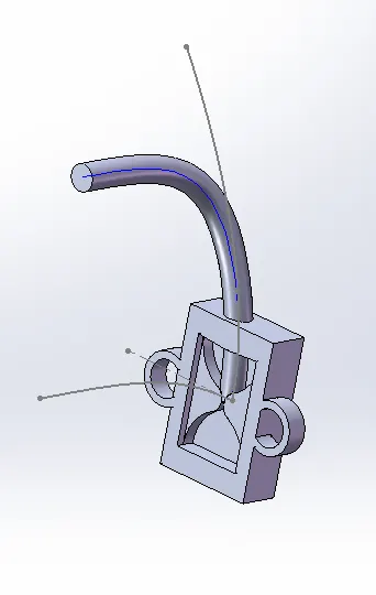
Project Curve feature projects a sketch curve onto a face or sketch.It is a tool used to form 3D curves from two 2D curves from two different planes. It is used to take two sketches and then project it onto a surface. For curved object modeling it gives a easy way to determine the sketches in three dimensional form. Because a curved object will have a different angle and different geometry while viewing from different planes. This tool sort out those things by taking two sketches of a same object from two different planes and gives a projected curve, which is the 3d curve of the object or geometry.
Reference Geometry:
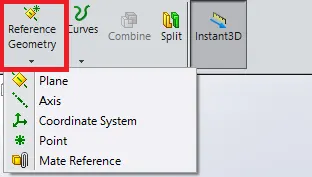
Reference Geometry feature commands are used to create a plane, axis and points etc,. to make a reference for geometry creations.Reference geometry includes reference planes, axis, coordinate systems, and points. The Reference geometry command lives on the Features toolbar, but you can also acces it from “Insert > Reference Geometry.
When the complexity of designs increases, it often becomes necessary to create and utilize reference geometry to produce models with appropriate design intent. By creating planes you can create geometry over that planes in order to create features like lofts and sweeps.
Surface Tools:
Surface tools used in modeling the trike are as follows:
Surface extrude – Creates an extruded surface.
Revolved Surface – Creates surface feature by revolving a open or closed profile around an axis.
Swept Surface – Creates a surface feature by sweeping an open or closed profile along an open or closed path.
Lofted Surface – Creates a lofted surface between one or more profiles.
Offset Surface – Creates offset surfaces using one or more contiguous faces.
Knit Surface – Combines two or more adjacent, non-intersecting surfaces together.
Extend Surface – Extends the edge, multiple edges or the face on the surface, based on end conditions and extension type.
Trim Surface– Trims a surface where one surface intersects with another surface, a plane, or a sketch.
Filled Surface – Constructs a surface patch within a boundary defined by existing model edges, sketches, or curves.
Delete Face – Delete faces from solid bodies to create surfaces, or deletes faces from a surface bodies.
Ruled Surface – Insert ruled surfaces from edges.
Mate:
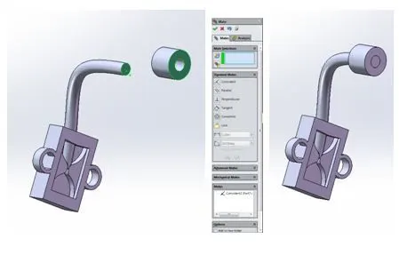
Mate assembly tool helps us to position two components relative to one another.
Once you have created the parts for the assembly, insert that part as components in New Assembly file (i.e. through dragging and dropping, or by “Insert components” tools in Assembly tool bar. One of the great benefits of Solidworks is that there are multiple ways to accomplish the same result and that also goes for mating.
You can use the “Mates Menu”, Quick Mates and Smart Mates to get the same result of mating.
Mates Menu can be find in Assembly Menu, on the Command Manager.
You can do Quick Mates, simply by holding down the Ctrl Key and select the two entities you wish to make
To create a Smart Mate, hold down the Alt Key, and left Click and drag the circular edge to the edge you want to mate it to.
As we have gathered basic knowledge about the features in Solidworks, let us put this in modeling ourtrike in Solidworks.
Now we are going to see each part associated with the trike and its design process alongside.
Each design comprises of three major steps:
- Sketching a 2D Geometry with proper dimensions and relations.
- Applying features as required.
- Applying appearances to convey the nature and the properties of the solids accordingly.
Ideation Sketch:
For modeling the trike: After getting some ideas, I sketched a hand sketch of my trike model and a demonstration sketch of how the leaning mechanism setup (parallelogram setup) is going to be.
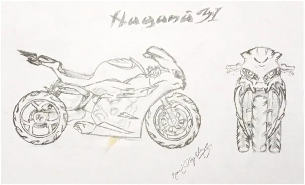
Fig. Hand sketched Ideation sketch of the trike model
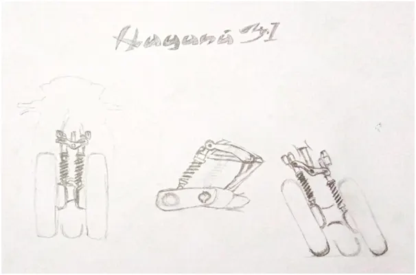
Fig. Demonstration sketch of how the leaning mechanism setup works.
From this Ideation sketches, I designed the whole trike by setting this ideation sketches as my blueprint.
The Blueprint Setup:
This is the blueprint setup of the ideation sketch which I used in modeling my trike parts.
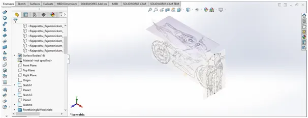
Fig. Blueprint setup
I also included a rough sketch for top view for modeling with some detail.
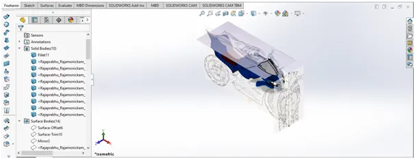
Fig. How the modeling work flows with the blueprint setup.
Connecting Arm and Swing Arm:
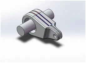
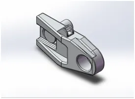
Fig. Connecting arm and swing arm
First I started designing the connecting arm and swing arm, for I thought it would be the base for the leaning mechanism (parallelogram setup) setup.
I just take reference dimension from cbr 950 swing arm and splitted the dimensions to make these two parts.
The solid modelingfeatures used in modeling these connecting arm and swing arm are boss extrude, cut extrude, revolve boss, mirror, linear pattern fillet and chamfer. I used surface modeling feature surface extrude to justcover the led bulbs I modeled in connecting arm.
Linkages:
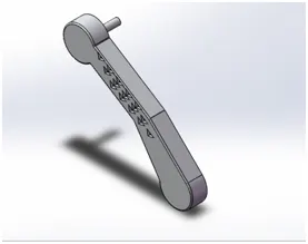
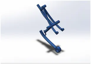
Fig. Parallelogram linkage and linkage frame
Next to connecting arm and swing arm, I started designing the linkages. These linkages are going to form the parallelogram setup with connecting, swing arm and independent suspensions.
First I modeled the parallelogram linkage, then I modeled the linkage frame. I used the blueprint setup of my ideation sketch to model these parts.
I used solid modeling tools like boss extrude, cut extrude, sweep, mirror linear pattern and fillet to model these parts.
Wheels:
Next, I modeled the wheels, as you see in my ideation sketch the rear wheels are lower to the front wheel as this project is mainly focused to add high rear side support to the passenger and make them feel the big rear wheel like experience I modeled like this.
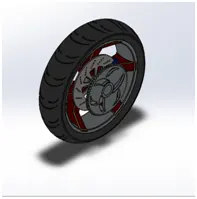
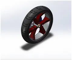
Fig. Rear wheel and front wheel.
I used solid modeling features like revolve, boss extrude, cut extrude, fillet, chamfer, mirror, circular pattern and combine.
I modeled a single rear wheel and mirrored it while assembly.
Frame:
This frame models front part is dimensioned and modeled with reference from the “Master thesis of comparison between a tubular frame and a beam frame”, as it is the model for recent day chassis/frame for the motorcycle.
And the back side frame, I modeled with the reference from my blueprint ideation sketch.
I used solid modeling tools like boss extrude, sweep, cut extrude, mirror, combine, fillet, loft, linear pattern, chamfer, revolve, cut revolve and surface modeling tools like surface loft and thicken.
This frame holds the front part, seating, fuel tank, tail fairing, engine and parallelogram linkage.
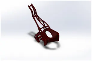
Fig. Frame
Main fairing:
While modeling the fairing, first I sketched with the blueprint setup and I used surface modeling tools like loft surface, thicken and solid modeling tools like boss extrude, mirror, combine, keep or delete body, split and fillet.
This fairing is going to be attached with the main frame and will give nice look to the trike by covering some engine part.
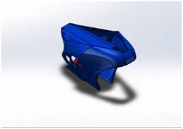
Fig. Main fairing.
Tail, front fairing, seat, fuel tank and windshield:
These parts are modeled with solid modeling and surface modeling tools, the surface modeling tools like surface extrude, trim surface, thicken, surface loft, delete face, mirror are widely used to design these parts. First, I modeled the windshield then front fairing, and then fuel tank, seat and tail fairing. I used solid model tools to design the seat.
I used the ideation sketch as blueprint to model these parts.
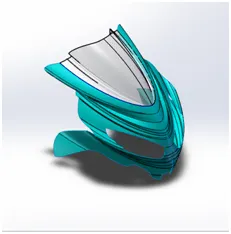
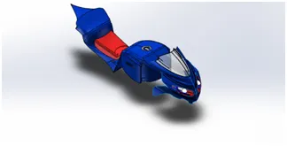
Fig. Front fairing with windshield and the whole part of tail, front fairing, seat, fuel tank and windshield.
Engine:
While designing the engine part, I faced challenges to design it. As I have no reference for this I have to go for a search to design an engine for different pitch diameter and connecting rod length. As I desired to place a 81 mm pitch bore diameter piston head and 97 mm length connecting rod in my engine, the search for designing it with correct parameters helped me to gain knowledge in designing the engine with different parameters.
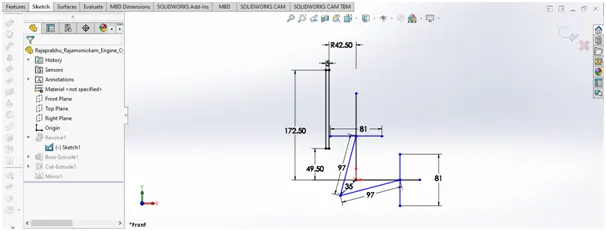
Fig. Base sketch for the engine cylinder.
This is how I get to model this complicated part with correct parameters I desired.
I mentioned this because these parameters is related with other parts like crankshaft, belts and each and every engine parts I listed below in figures:
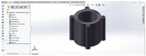
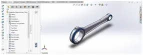
Fig. Engine Cylinder and Connecting rod.
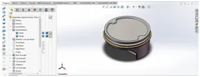
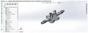
Fig. Piston head and Crankshaft
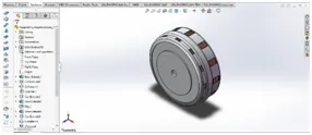
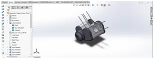
Fig. Clutch and Crank case.
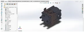
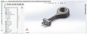
Fig. Enginehead and Cam bracket.
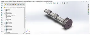
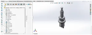
Fig. Cam shaft and Sparkplug.
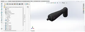
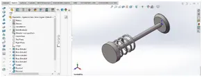
Fig. Sparlplug cap and Valve.
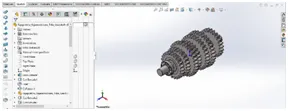
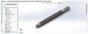
Fig. Gearset and Countershaft.
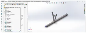
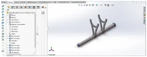
Fig. Dog cluthces.
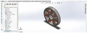
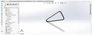
Fig. Armature Motor and belt
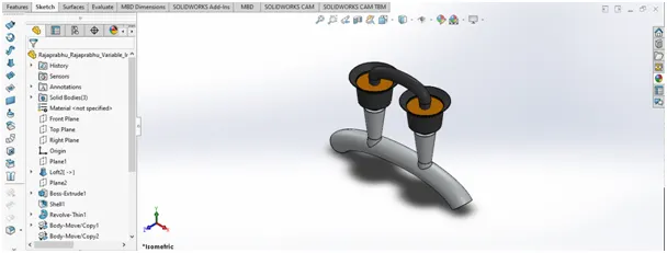
Fig. Variable Intake.
For modeling this variable intake I take inspiration from ducati engines. And the engine I designed have some ducati references as I inspired and desired to model one of its kind.
Fig. Driven gear and Idler gear.
Some other trike parts:
I used solid modeling features to design the following necessary parts for trike:
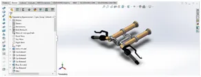
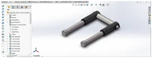
Fig. Triple clamp and fork.
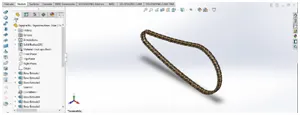
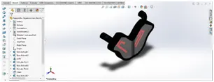
Fig. Chain and backlight.
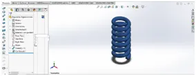
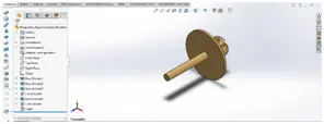
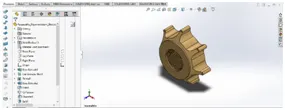
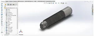
Fig. Suspension parts.
Assembly:
The term mechanical assemblyis most often referred to putting components together in an assembly line, but more specifically, it refers to creating a complete product that performs an intended function.
In this solid modeling we use bottom up approach, as we designed the parts individually.
Mate is the main tool used in assembly for mating the parts together, i.e. assembling the parts with correct mating relation with the parts.
Sub assembly: Engine head and Full engine assembly
I startedthe assembly from engine head sub assembly by importing the engine head componentfrom import component selection pane. Then with this engine head assembly I assembled whole engine assembly with crankcase with all engine parts.
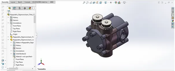
Fig. Engine head assembly
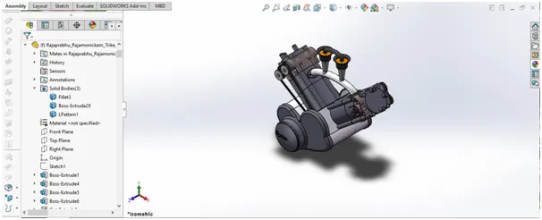
Fig. Engine assembly
Orientation Views of Engine head assembly and Engine assembly:
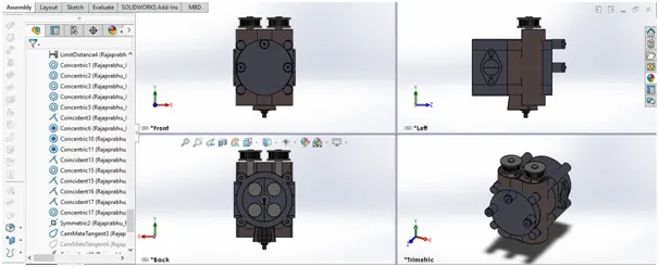
Fig. Engine head assembly
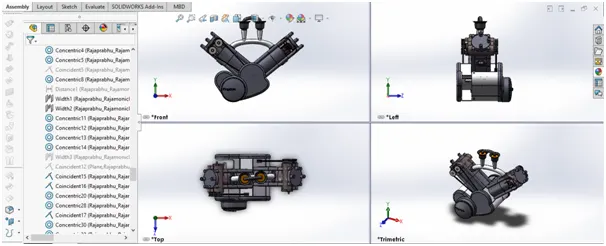
Fig. Engine Assembly
Full Assembly:
After assembling the engine head assembly and engine assembly, I started assembling the whole with the parts I have modeled.
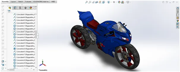
The mates used in assembling the parts are:
Coincident mate, concentric mate, cam tangent mate, parallel mate, tangent mate, distance mate, limit distance mate, width mate, limit angle mate, gear mate, lock mate and symmetric mate.
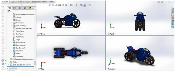
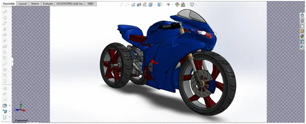
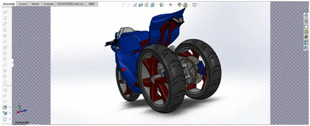
Different Views of Assembly model of trike:
Orientation Views:
Camera Views:
Leaning mechanism provided by Parallelogram Linkage setup:
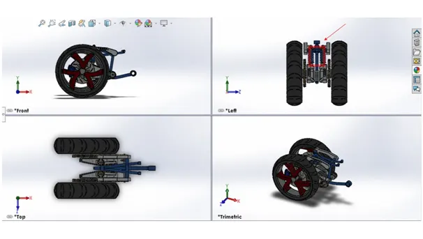
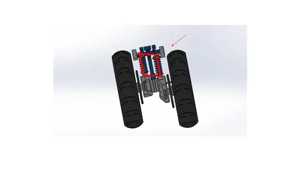
This two rear wheel and parallelogram linkage and independent suspense setup will provide good grip to give some time to the passenger to sense the drifting while in case of any accidental situation, and easily took control over the rear brake to stable back the vehicle or just escape from the vehicle to avoid injuries when they decide to leave vehicle and get rid of that, as I placed two wheels on rear side and its position is designed to be at a distance from seating center it will provide good escape from injuries that was caused during accidents.
Rendering:
Rendering is the process of generating a photorealistic or non-photorealistic image from a 2D or 3D model utilizing a computer program. At present, there are multiple computer programs available to perform the rendering.
The rendering of a CAD model in Solidworks can be done by using the following software & the first two software are widely used for rendering.
- Photoview 360
- Solidworks Visualize.
- Onshape
- Keyshot
- Blender
In order to render image for the object you must create a camera view otherwise you must enable perspective view.
In this project, I do the renders through Photo View 360 add-in.
Photoview 360 add-in can be found in menu tab by enabling it from ”Tools> Add-in” Option.
By enabling it you can also get a Render tools tab, from there you can edit a scene, edit decals and adjust the render option to render the object.
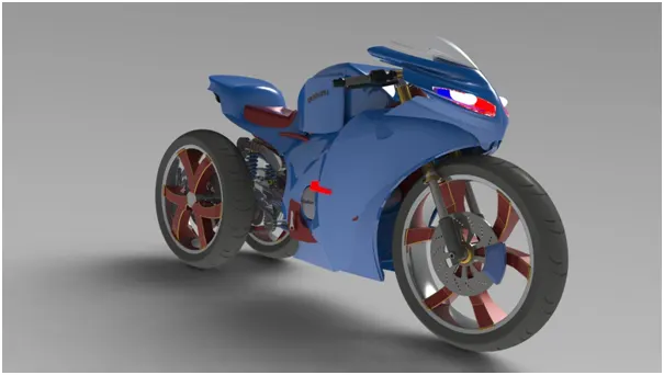
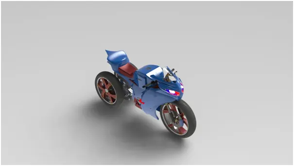
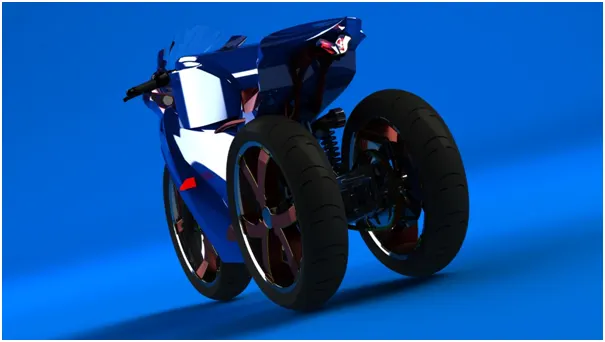
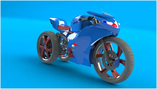
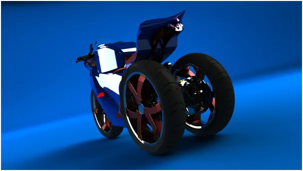
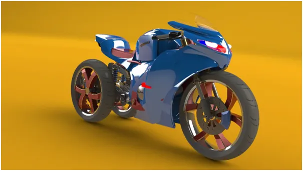
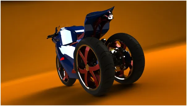
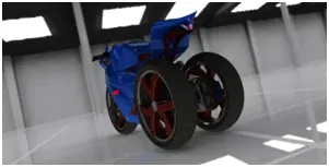
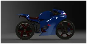
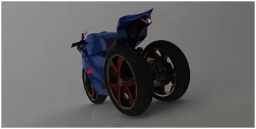
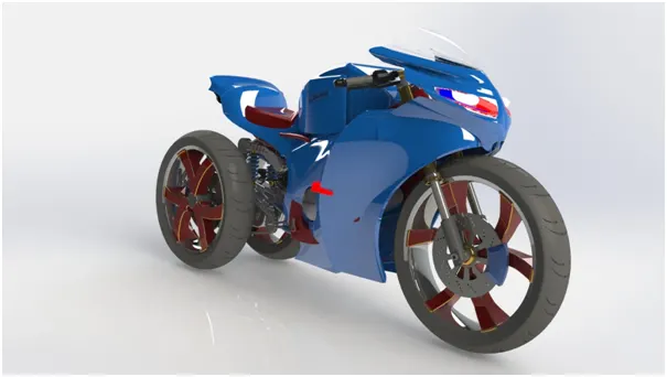
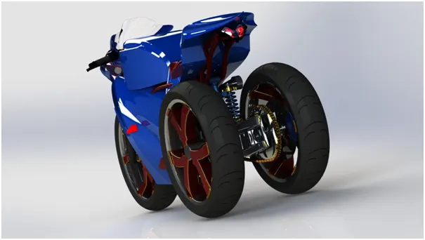
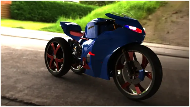
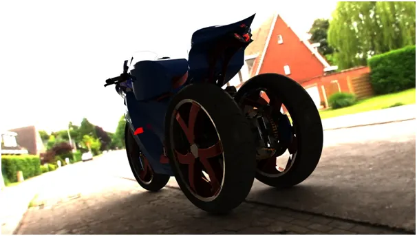
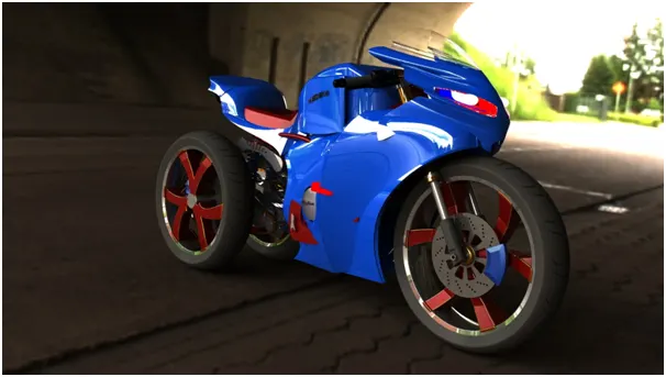
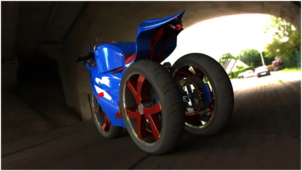
Following are the renders of the trike in different views and in different environments.
In each render I adjusted the lighting brightness and environment rotation.
Studio Rendering:
In Grey backdrop environment:
In Blue backdrop Studio environment:
In Orange backdrop studio environment:
Ware house and flourescent light studio environment:
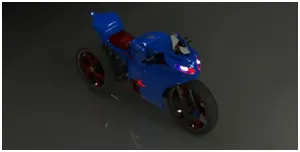
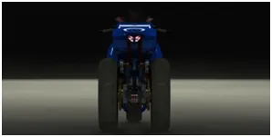
In Biege environment:
Outdoor rendering:
Location: Ekeren bridge, Belgium
FUTURE SCOPE:
- Fabrication and Analysis of the design.
- Implementing real world changes in design to produce the vehicle in mass numbers.
CONCLUSION:
The design of tilting trike with two rear wheels and one front wheel with suspensions at rear wheel frame model is successfully designed and modeled using solidworks.
This trike model with parallelogram setup will provide safety to the passengers riding the motorcycle and cutoffs the accidents caused due to slippages and roll out.
REFERENCES:
- Piaggio files patent for three-wheeler with leaning rear wheels – https://www.google.com/amp/s/www/motopinas.com/motorcycle-news/piaggio-files-patent-for-three-wheeler-with-leaning-rear-wheels/amp.
- Yamaha planning sportier three-wheeler – https://www.bennetts.co.uk/bikesocial/news-and-views/news/2019/febraury/yamaha-planning-sportier-three-wheeler.
- A Leaning Custom Harley Trike Motorcycle Freewheeler – https://siamagazin.com/a-leaning-custom-harley-trike-motorcycle-freewheeler.
- IRJET (e-ISSN:2395-0056, p-ISSN: 2395-0072) – Design of Tilting Reverse Trike – by Yadav Rajnath, Nair Siddarth, Bhagat Zeelkumar, Suthar Ashok, Nilesh Vasawala, Dhruv Solanki. Volume 07, Issue: 05, May 2020. Pg No. 5041-5046.
- IRJET (e-ISSN:2395-0056, p-ISSN: 2395-0072) – Design and Fabrication of Tilting Trike – by BinuHaridas, Aswin Jayaprakash, Bibin Benny, Johnson Kuriakose, Joseph V George. Volume 06, Issue: 05, May 2019. Pg No. 4305-4307.
- Leaning Trikes using Rear Axle Pedal Crank Mechanism – by Stephen Nurse, Monash University, Melbourne, Australia, November 2013 – ResearchGate.Net – December 2013 article.
- Master thesis of Comparison between a tubular frame and a beam frame – https://upcommons.upc.edu/handle/2099.1/14372 - Locutura More, Joan and Federico Cheli. 2010