Radar Mast & Final Assembly of Yacht
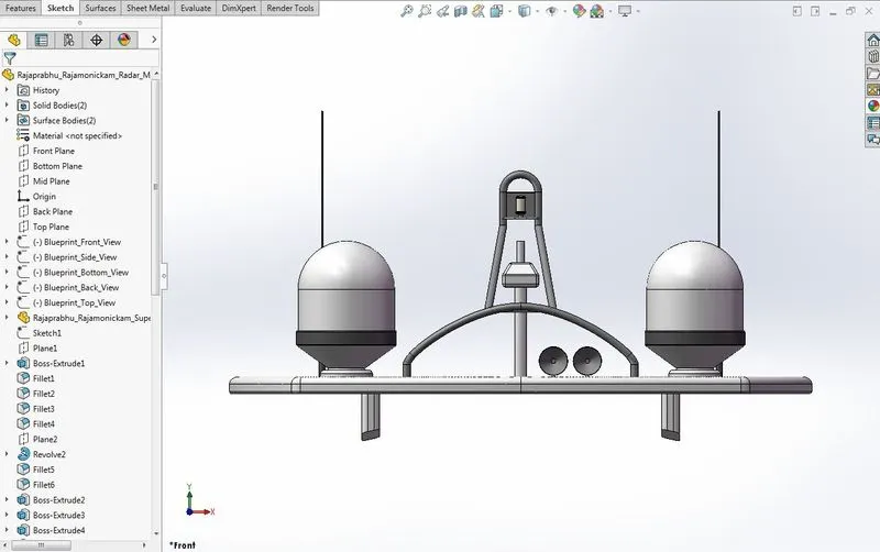
Radar Mast:
Front View
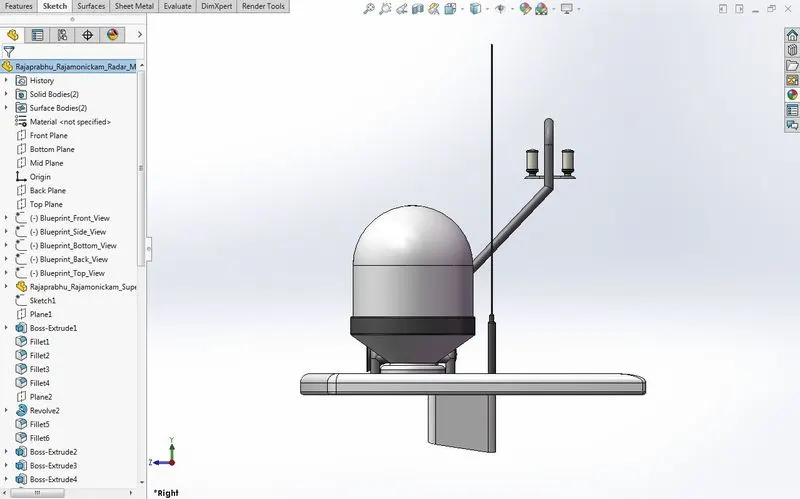
Side View
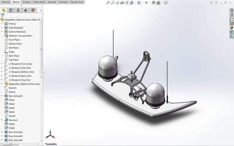
Isometric View
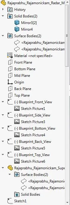
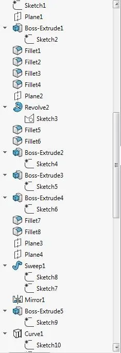
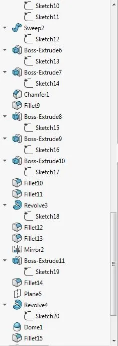
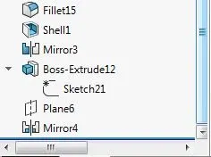
Feature Tree
Assembly of Yacht:
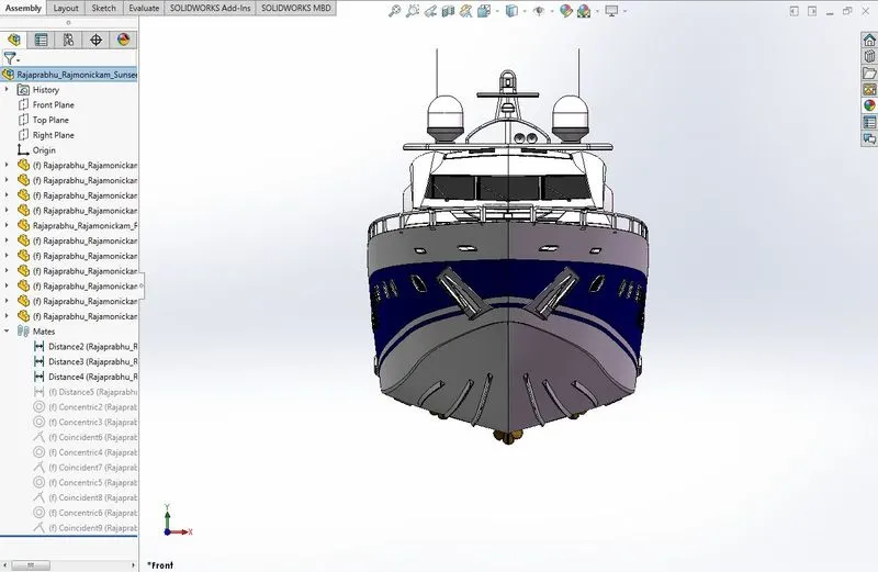
Front View
Side View
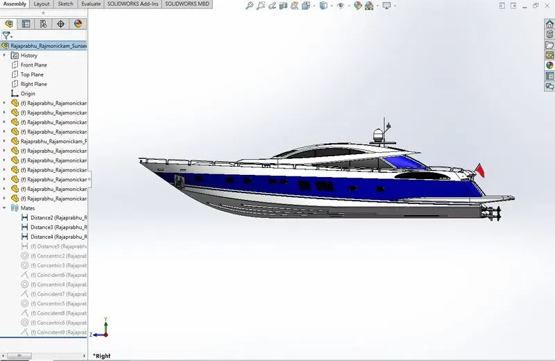
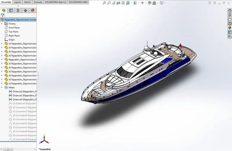
Isometric View
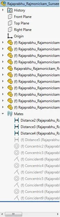
Assembly Tree
PROJECT:
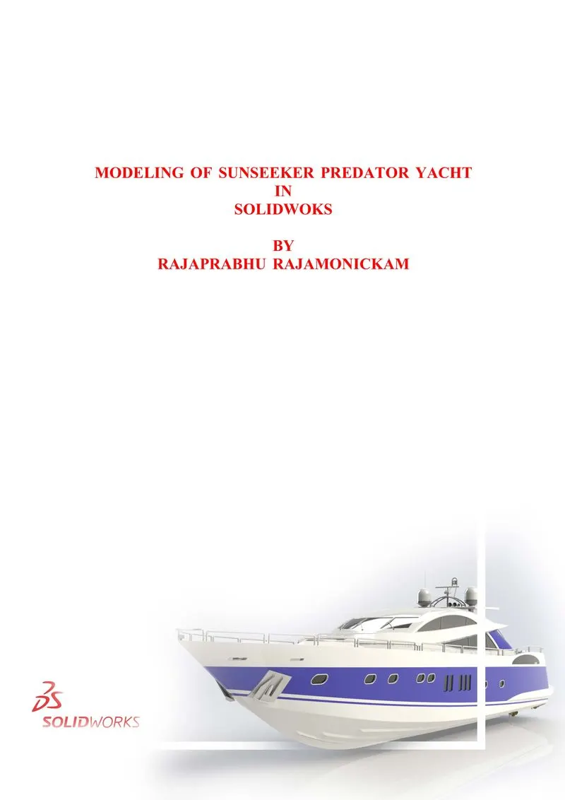
MODELING OF SUNSEEKER PREDATOR YACHT IN SOLIDWORKS.
OBJECTIVE:
To design a model of Sunseeker Predator Yacht using SolidWorks CAD software with basic features like sketching a geometry and composing it into 3D Model and rendering it to visualize as a realistic object.
INTRODUCTION:
Modeling:
A Model is a mathematical representation of a geometric form, which is stored in the computer memory. 2D Models are recognized by the system as flat frameworks bounded by a number points, which are defined by X and Y Cartesian coordinates. A 3D Model may be held in computer memory by specifying points with a third Z coordinate.
Viewing an object in 3 dimensions helps to get a sense of its true shape and form. It also helps in design, which in turn allows us to make better design decisions. It helps to communicate our ideas to those who may not be familiar with the orthographic views including sections and side views of design.
In this project we are going to see the entire modeling of a Sunseeker Predator Yacht in SOLIDWORKS.
Solidworks contains the capabilities to produce 3D Models. These capabilities are used interactively with 2D drawings.
The different components of the yacht we deal with are:
- Propeller
- Radar and Radar Mast
- Hull
- Superstructure
- Garage Door
- Front Seat
- Middle Seat
- Rear Seat.
After designing the part components, I worked the assembly and the Photo rendering of the yacht which gives the model a complete and realistic view.
DESIGN METHODOLOGY:
Design methodology of the yacht model is described step by step in the following flow chart:
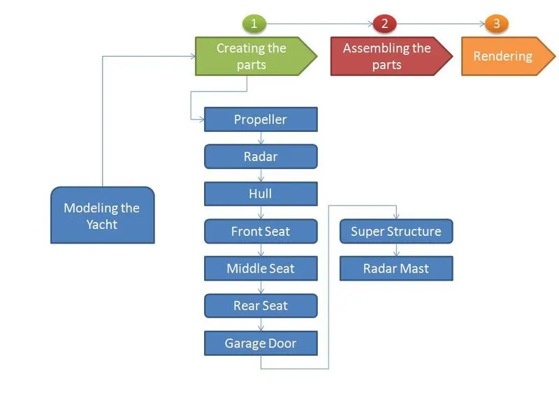
Fig. Design Methodology of the Yacht.
The features and properties given inside the SOLIDWORKS Software makes it easier to compose a 3D Object from a 2D Sketch.
Let’s have a look into the features which is used in the process of modeling the entire model of the yacht:
1.Extruded Boss/Base.
2.Fillet.
3.Lofted Boss/Base.
4.Extrude Cut.
5.Split.
6.Shell.
7.Revolve Boss/Base.
8.Linear Pattern.
9.Combine.
10.Dome.
11.Mirror.
12.Projected Curve.
13.Reference Geometry.
14.Surface tools.
Extruded Boss/Base:
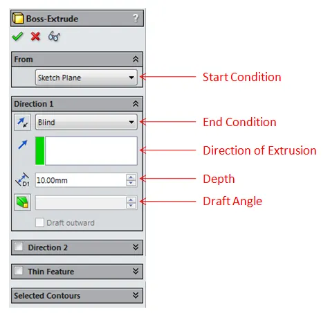
The Extruded Boss/Base feature extrudes a sketch or selected sketch contours in one or two direction to create a solid feature. It is the feature used after a sketch. To extrude an object, sketch the object geometry in two dimension sketch. Make proper dimension and relation to that geometry and then click the Extrude Boss/Base from Feature tab. It extrudes the geometry into an object with the options like Blind which uses the direction and depth. And there are so many ways to extrude that object with the options like From Surface/Face/Plane, Vertex and Offset which dropdowns from the From Option in Boss-Extrude. Sketch plane and blind are the default options present in the Boss-Extrude. You modify the Options in “From” and Direction1, Direction2. etc., to obtain required type and shape of the extrude.
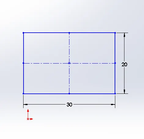
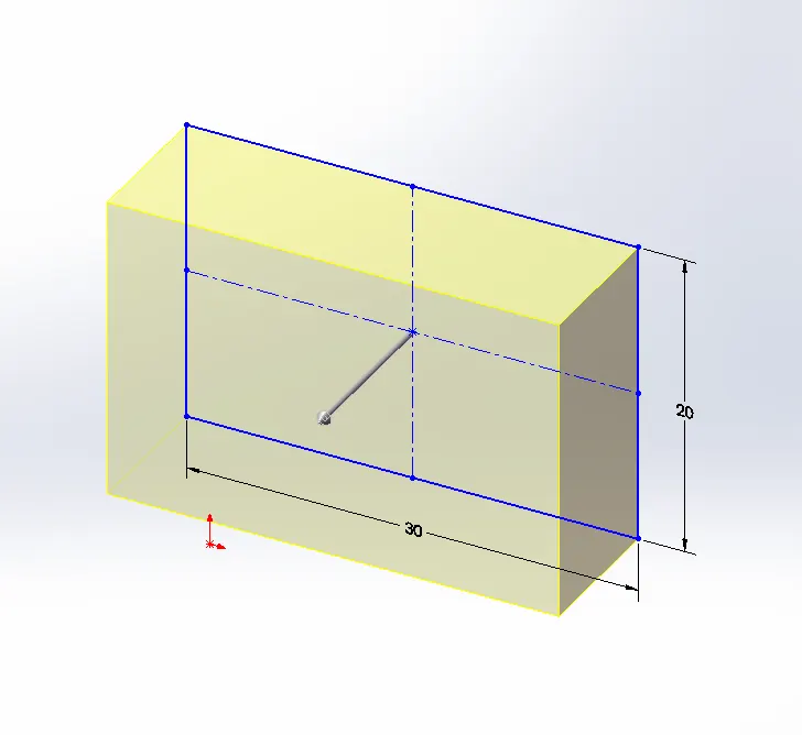
We can modify Start Condition, End Condition, Direction of Extrusion, Depth, Draft Angle to get different type of Extrudes for a geometry.
Fillet:
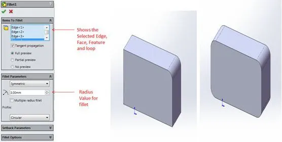
Fillet feature creates a rounded internal and external face along one or more edges in solid or surface feature. It is used to fine the edges in the model with the radius value. We can fillet the edges, face, feature and loops by selecting the appropriate item which is displayed in “Item to fillet” selection box.
Lofted Boss/Base:
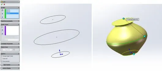
Lofted Boss/Base feature adds material between two or more profiles to create a solid feature. Lofted Boss/Base uses multiple Profiles and Guide curves to make a loft in respective to the geometry. It is very helpful tool to create complex surfaces in the model.
Extrude Cut:
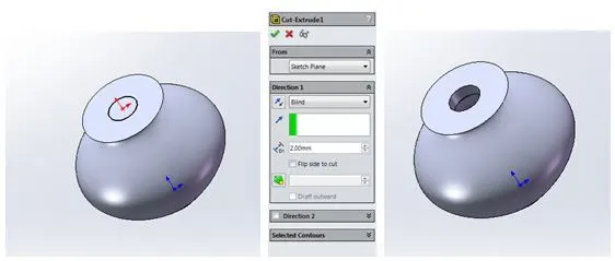
Extrude Cut feature cuts a solid model by extruding a sketched profile in one or two dimensions. This feature extrude cut the object with the options like From Surface/Face/Plane, Vertex and Offset which dropdowns from the From Option in Cut-Extrude which is similar to that in Extrude boss feature.
Split:
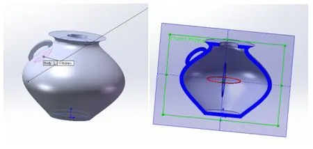
The Split feature is an extremely useful tool when designing using multibody part techniques in Solidworks. Split feature cuts out the unwanted body/part from the design as per our requirements. Split feature works with surfaces/solids. You can have the cut removal of the selected bodies even as optional using consume cut bodies check box. Split feature modifies bodies and even create new bodies by splitting it up when you deselect the consume cut bodies check box.

Shell:
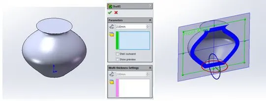
Shell feature removes material from a solid body to create a thin walled feature. When there is an object ready in the model you can simply select the “Shell” Option and give the thickness value. It will automatically create shell inside the object. You can check it in section view as it does real quick and easier.
Revolved Boss/Base:
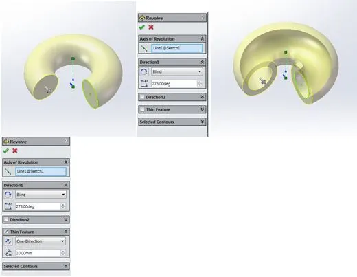
Revolved Boss/Base feature revolves a sketch or selected sketch contours around an axis to create a solid feature. Revolved Boss features are very useful in creating wheel, hub and some revolve objects. You can create two types of revolve in a single sketch, by selecting the thin feature option you can revolve the object like an offset from your sketch. When you deselect the thin feature, it gives a full contour revolve of your sketch.
Linear Pattern:
Linear Pattern feature patterns features, faces and bodies in one or two linear directions at required instances.
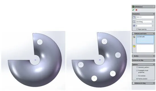
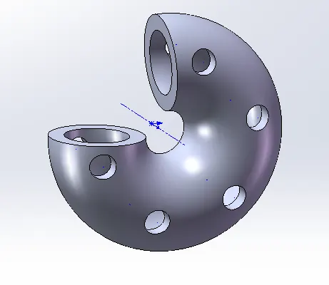
Under Linear Pattern feature there several types of patterning features such as Circular Pattern, Curve driven pattern and Sketch Driven pattern .etc,. We can turn on View temporary axis to get a quick patterning of bodies, sketches and features without having to sketch a separate construction geometry.
Combine:
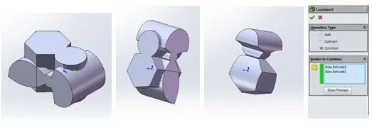
Combine feature combines two or more solid bodies. There are three different ways to use Combine; You can add, subtract, and find the common area of two different bodies. You will need multi-body part for this feature. The Combine feature lives under “Insert > Features > Combine”.
Dome:
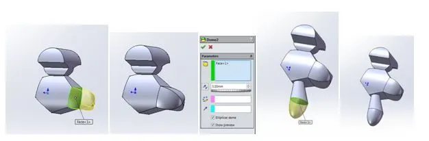
Dome feature adds one or more domes to selected planar or non-planar faces. In dome feature you can add elliptical or continous surface dome to the surface or face of the model. You can add Domes by navigate through the “Insert> Features> Dome”. Select the appropriate face/surface in which you have to make a Dome.
Mirror:
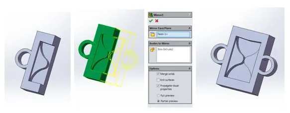
Mirror feature mirrors features, faces, and bodies about a face or a plane. By selecting a face/Plane you can mirror the object which will create a perfect opposite mirror copy of the original object. You can merge the bodies which is mirrored selecting the “Merge result” check box or else through combine feature.
Project Curve:
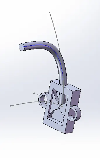
Project Curve feature projects a sketch curve onto a face or sketch. It is a tool used to form 3D curves from two 2D curves from two different planes. It is used to take two sketches and then project it onto a surface. For curved object modeling it gives a easy way to determine the sketches in three dimensional form. Because a curved object will have a different angle and different geometry while viewing from different planes. This tool sort out those things by taking two sketches of a same object from two different planes and gives a projected curve, which is the 3d curve of the object or geometry.
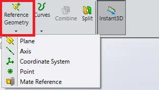
Reference Geometry:
Reference Geometry feature commands are used to create a plane, axis and points etc,. to make a reference for geometry creations. Reference geometry includes reference planes, axis, coordinate systems, and points. The Reference geometry command lives on the Features toolbar, but you can also acces it from “Insert > Reference Geometry.
When the complexity of designs increases, it often becomes necessary to create and utilize reference geometry to produce models with appropriate design intent. By creating planes you can create geometry over that planes in order to create features like lofts and sweeps.
Surface Tools:
Surface tools used in modeling the yacht are as follows:
Surface extrude – Creates an extruded surface.
Revolved Surface – Creates surface feature by revolving a open or closed profile around an axis.
Swept Surface – Creates a surface feature by sweeping an open or closed profile along an open or closed path.
Lofted Surface – Creates a lofted surface between one or more profiles.
Offset Surface – Creates offset surfaces using one or more contiguous faces.
Knit Surface – Combines two or more adjacent, non-intersecting surfaces together.
Extend Surface – Extends the edge, multiple edges or the face on the surface, based on end conditions and extension type.
Trim Surface – Trims a surface where one surface intersects with another surface, a plane, or a sketch.
Filled Surface – Constructs a surface patch within a boundary defined by existing model edges, sketches, or curves.
Delete Face – Delete faces from solid bodies to create surfaces, or deletes faces from a surface bodies.
Ruled Surface – Insert ruled surfaces from edges.
Mate:
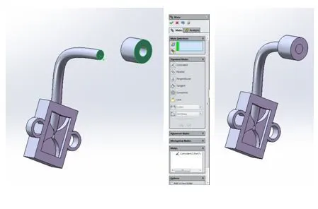
Mate assembly tool helps us to position two components relative to one another.
Once you have created the parts for the assembly, insert that part as components in New Assembly file (i.e. through dragging and dropping, or by “Insert components” tools in Assembly tool bar. One of the great benefits of Solidworks is that there are multiple ways to accomplish the same result and that also goes for mating.
You can use the “Mates Menu”, Quick Mates and Smart Mates to get the same result of mating.
Mates Menu can be find in Assembly Menu, on the Command Manager.
You can do Quick Mates, simply by holding down the Ctrl Key and select the two entities you wish to make
To create a Smart Mate, hold down the Alt Key, and left Click and drag the circular edge to the edge you want to mate it to.
As we have gathered basic knowledge about the features in Solidworks, let us put this in modeling our Sunseeker Predator Yacht in Solidworks.
Now we are going to see each part associated with the Sunseeker Predator Yacht and its design process alongside.
Each design comprises of three major steps:
- Sketching a 2D Geometry with proper dimensions and relations.
- Applying features as required.
- Applying appearances to convey the nature and the properties of the solids accordingly.
Propeller:
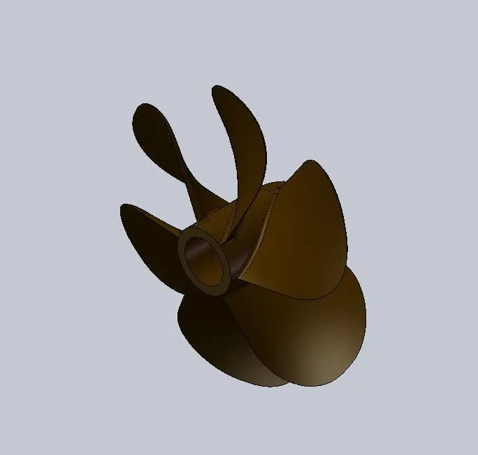
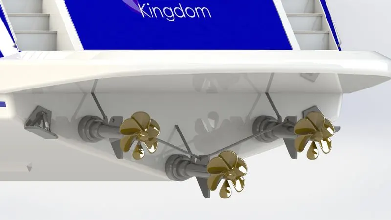
In this Yacht we have three propellers, here I design one propeller and while making assembly I will place this part thrice to the assembly. Starting with a sketch, I used revolve feature to make the hub. Then I used Loft, Cut Extrude, Circular pattern features to create the blades of the propeller. To add some details to this solid body I add some fillet around the edges and set the appearance of the propeller to a custom brown color in Appearances tab.
Radar:
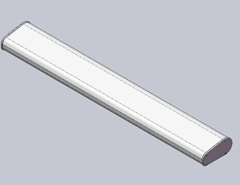
In designing the radar, I used 2d sketching and features like boss extrude. Cut extrude, Sketch Pattern, Mirror and Split line.
To add some text in the other side of the radar I used the sketch tool “Text” which is used to sketch text on faces, edges and surfaces. To add some details I gave a “White” Appearance to the radar.
Hull:
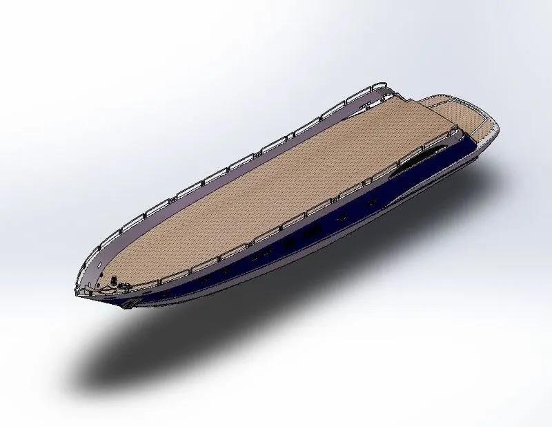
To model the hull part of the yacht first I inserted the blue print of the yacht and setup the blueprints on Front, Back, Top, Mid and Bottom planes. Then I started sketching and made Projected Curves, used Surface tools like Surface lofts, Surface Extrude, Surface Trim, Surface Knit, Surface Fill, Delete face, Offset surface and Feature tools like Boss extrude, Cut extrude, Revolve Boss, Linear Pattern, Sweep, Mirror, Save bodies and Split Line tools. I added some fillets and chamfer feature to fine the edges. In Appearances to get a bright look for hull I added “White” color appearance for body of the hull, custom grey color for rails, black color for propeller axle and blue color appearances for some faces. To get some woody appearance in the deck surface, garage and steps I inserted some custom wooden patterned decals.
Front Seat:
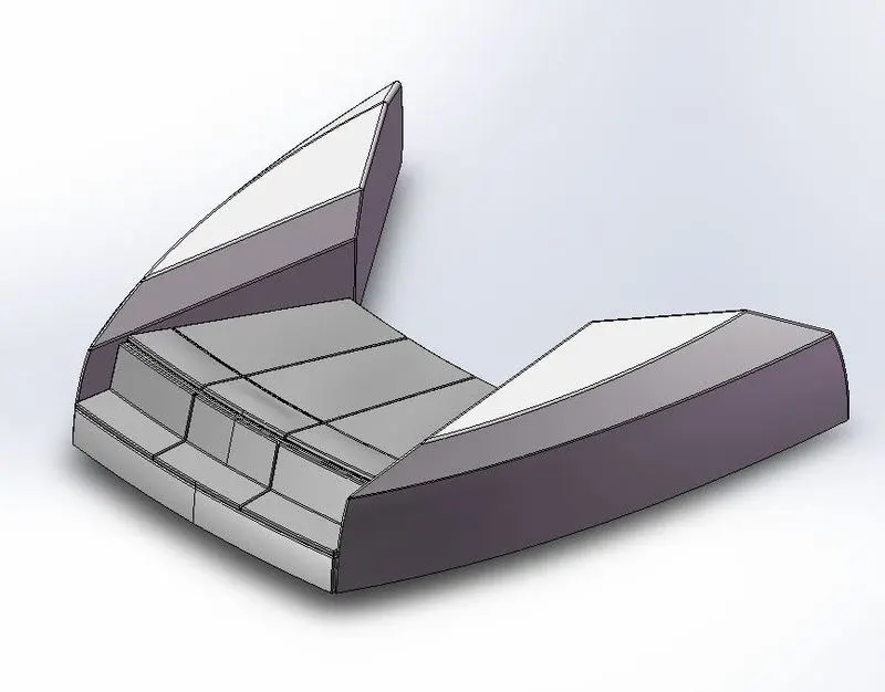
In Front Seat designing, I started designing from setting up the blueprint as set in Hull part designing. As I have saved the blueprint setup as a separate I used them first to reference for my sketching of front seat and also in upcoming part designing of yacht. I used surface tools such as surface sweep, surface extrude, surface loft, surface trim, surface fill, surface knit and Feature tools such as revolve, Cut extrude, Mirror, Dome, Fillet and Chamfers. I gave a white color appearance for the body of the front seat and given a custom grey color for mattresses.
Middle Seat:
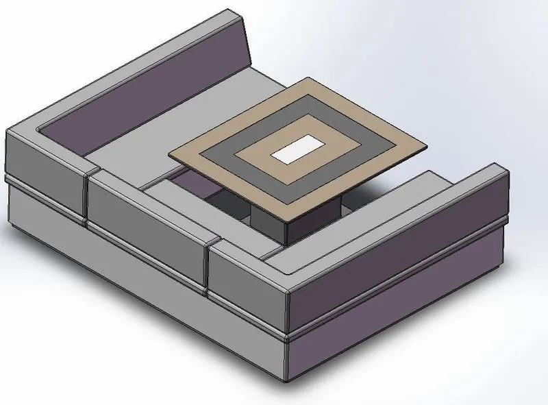
In modeling the middle seat, I started with the blueprint setup. Then, I started sketching and used Boss Extrude, Cut extrude, Mirror features from Features tool bar. And finally I made some fillets and chamfer to fine the edges. I added white color appearance for the body at base, custom grey color for mattresses in seats and added some custom brown, white and dark grey color for table.
Rear Seat:
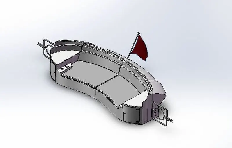
Now in this part, I started with the blueprint to sketch the rear seat in 2d sketch one by one. Then I used surface tools such as Surface sweep, Surface offset, Surface Trim, Ruled Surface, Surface Knit, Surface extend, Surface loft, Surface extrude, Surface offset tools and Boss extrude, Cut extrude, Sweep, Mirror, Revolve, Fillet and Chamfer features from Feature tools to achieve this model of seat, Mattresses, flag, flag pole and side rails. For body of the rear seat I used white color, for flag I used red color and for mattresses and rails I used custom grey and dark grey color using Appearance options.
Garage Door:
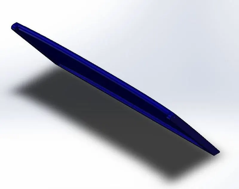
Garage door is a simple sketch model which is made by 2d sketches and features like shell, Cur extrude, Mirror, Reference plane and fillets. For getting a text carved on the front side of the garage door, Text Sketch tool is used.
Applied dark blue color for the garage door and white color for the text using Appearance option.
Super Structure:
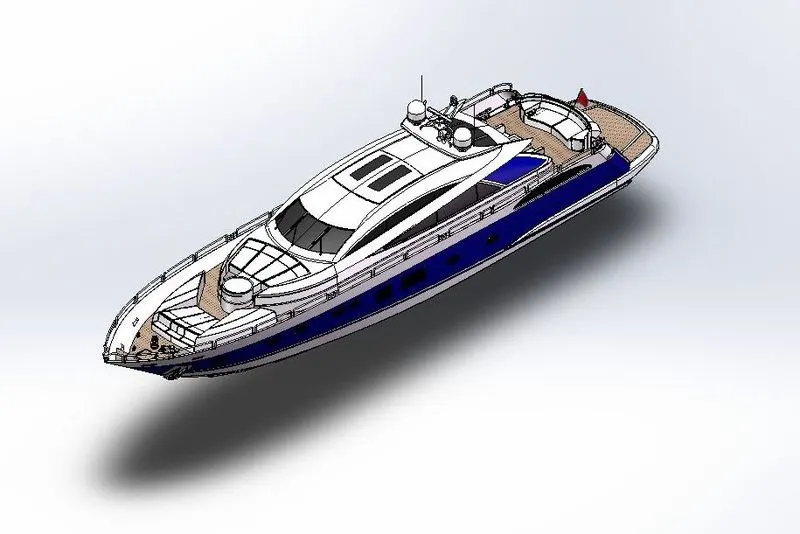
Superstructure part modeling starts from blueprint referenced sketches. Surface tools used in these part model are Surface extrude, Surface Sweep, Surface Knit, Ruled Surface, Surface Trim, Surface Loft, Surface fill, Surface extend and Surface offset. Feature tools such as Projected Curve, Cut extrude, Boss extrude, Mirror, Fillets, Chamfer and Reference geometry are also used.
White Appearance is applied to the body of the superstructure, custom grey color for Mattresses and a transparent blue color Jacuzzi water and for Jacuzzi steps custom wooden decals are used.
Radar Mast:
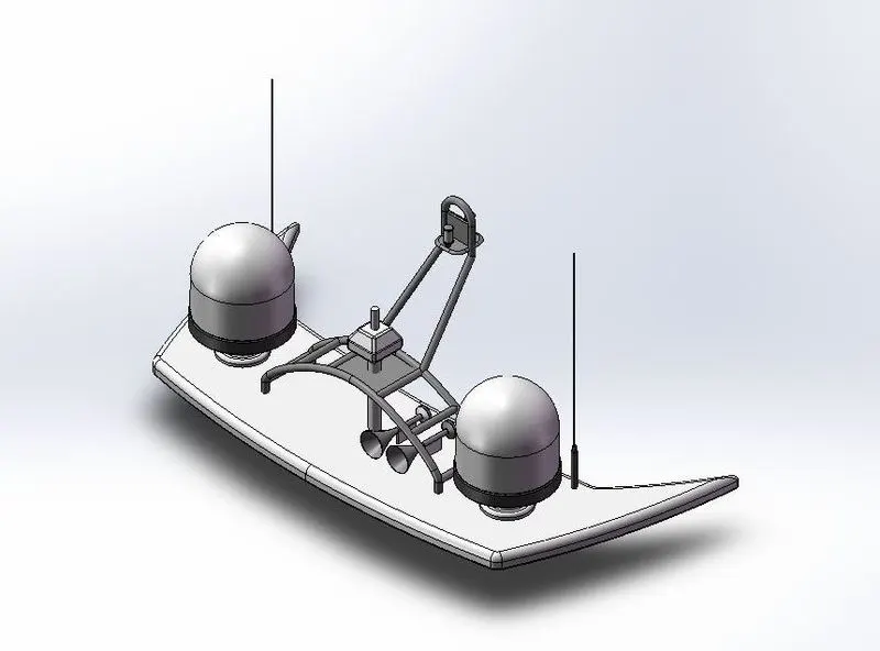
Radar mast is modeled by using 2d sketches, boss extrude, Revolve Boss, Projected Curve, Sweep, Mirror, Fillet, Chamfer, Dome and Shell features.
Appearance for radar mast is set to White, and some parts with grey and lights with custom light yellowish.
Assembly:
The term mechanical assembly is most often referred to putting components together in an assembly line, but more specifically, it refers to creating a complete product that performs an intended function.
In this solid modeling we use bottom up approach, as we designed the parts individually.
Mate is the main tool used in assembly for mating the parts together, i.e assembling the parts with correct mating relation with the parts.
We start assembly by fixing every parts just by clicking the Ok button on import component selection pane. It will automatically fixes to the parts assembled. Then we assemble the rear seat with coincident and distance mate. Garage Door and Propellers are assembled with coincident and concentric mate and then fixed.
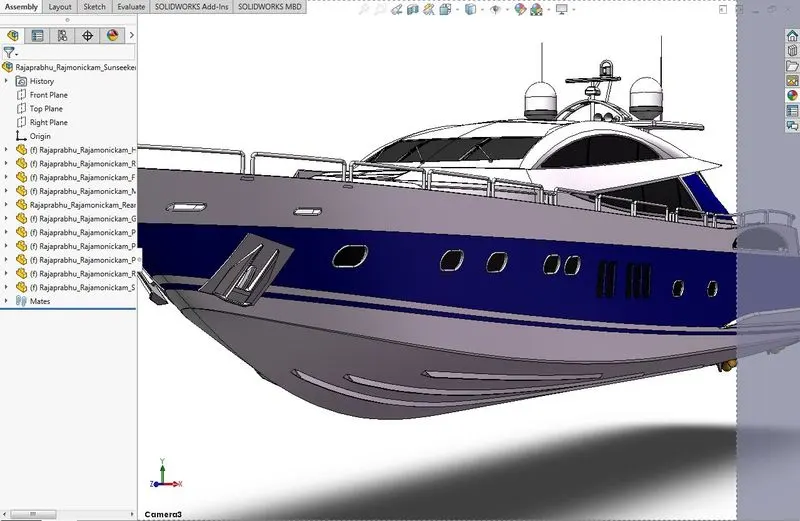
Different Views of Assembly model of yacht:
Front View
Side View
Isometric View
Top View
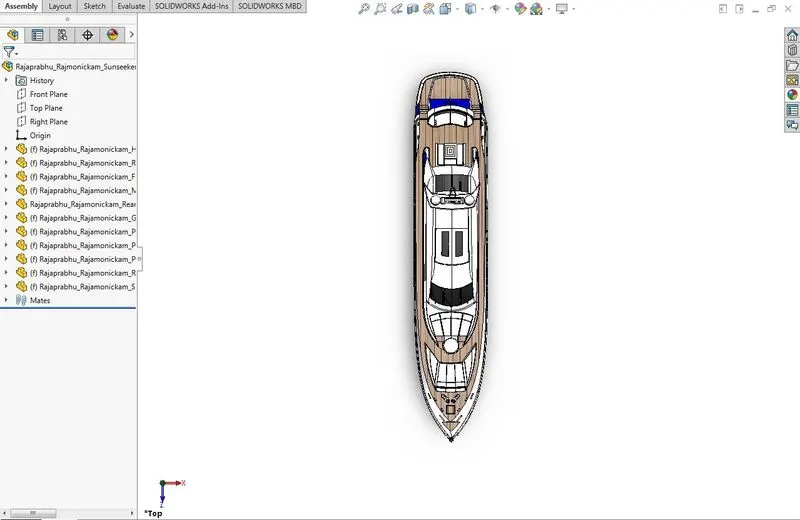
Camera View
Rendering:
Rendering is the process of generating a photorealistic or non-photorealistic image from a 2D or 3D model utilizing a computer program. At present, there are multiple computer programs available to perform the rendering.
The rendering of a CAD model in Solidworks can be done by using the following software & the first two software are widely used for rendering.
- Photoview 360
- Solidworks Visualize.
- Onshape
- Keyshot
- Blender
In order to render image for the object you must create a camera view otherwise you must enable perspective view.
In this project, I do the renders through Photo View 360 add-in.
Photoview 360 add-in can be found in menu tab by enabling it from ”Tools > Add-in” Option.
By enabling it you can also get a Render tools tab, from there you can edit a scene, edit decals and adjust the render option to render the object.
Following are the renders of the yacht in different views and in different environments.
In each render I adjusted the lighting brightness and environment rotation.
Three Point Biege Render:
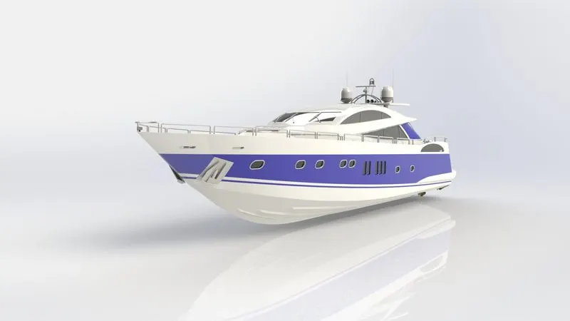
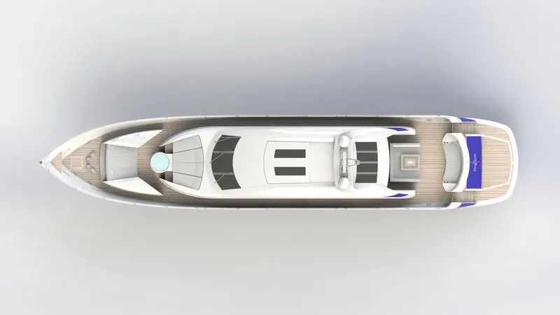
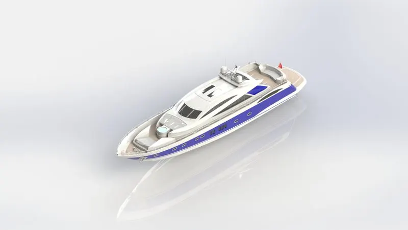
After creating the yacht, I used three point biege scene and studio environment to quickly grab the idea and visualization of the yacht. Adjusting the lighting brightness from Photoview 360 lighting tab in Edit Scene option gives a nice bright look of the yacht.
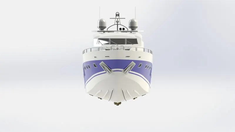
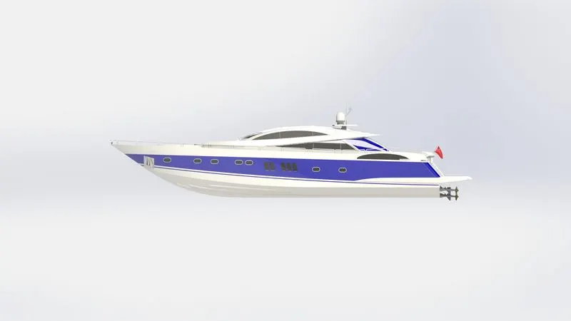
Different views of Sunseeker Predator Yacht in Three point biege render:
Front View
Side View
Top View
Iseometric View
Camera Views
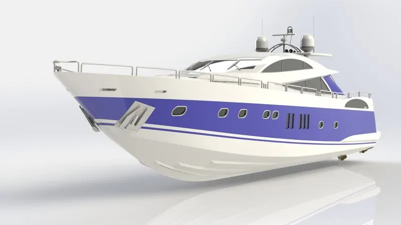
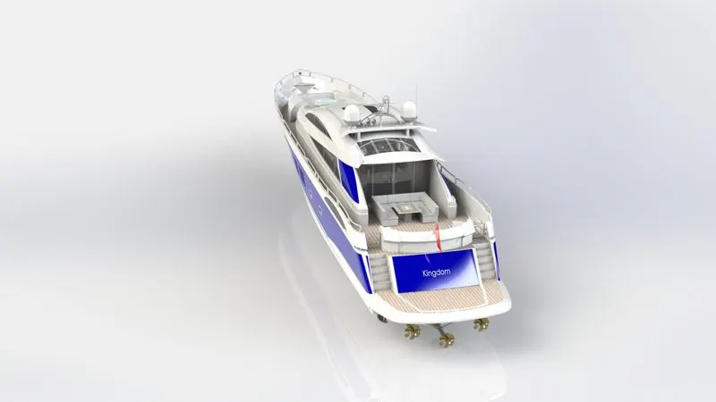
I added three camera views to the yacht. I am going to use any of this camera and standard views for the following renders.
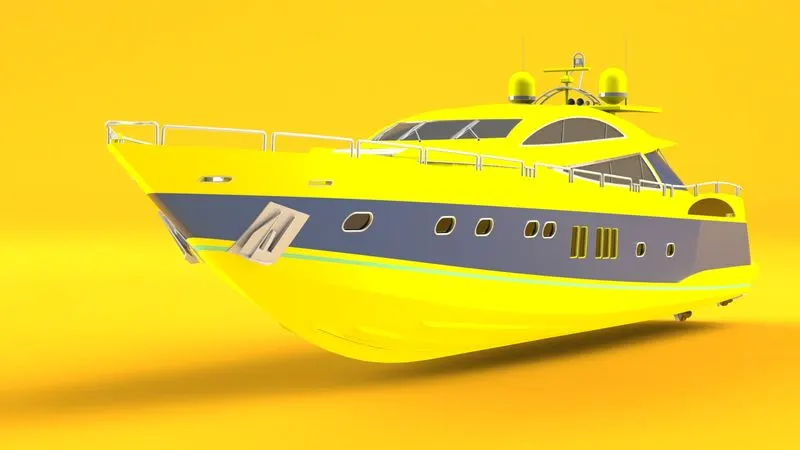
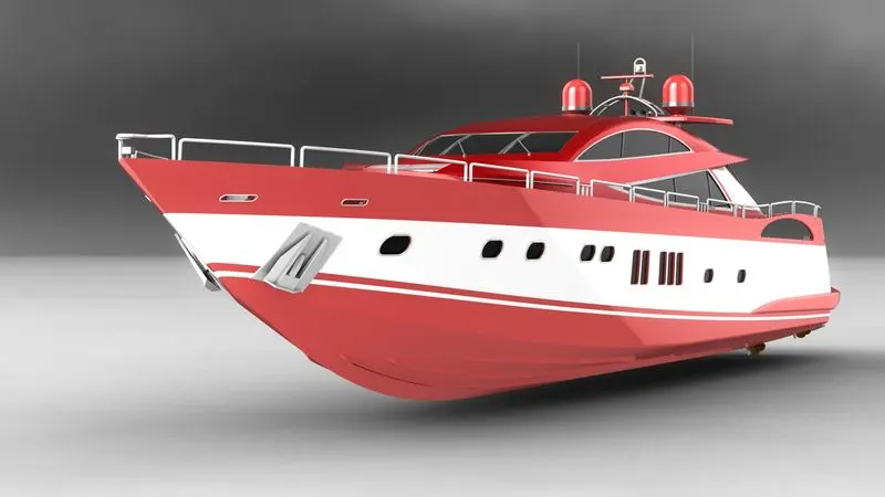
I named the following render variants based on its appearance and purpose.
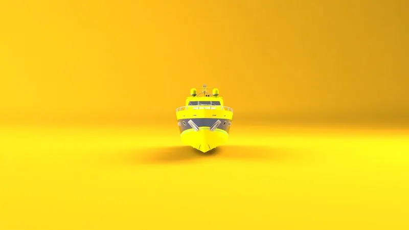
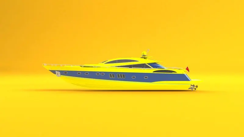
Yellow Variant:
Additional Views
Front View
Side View
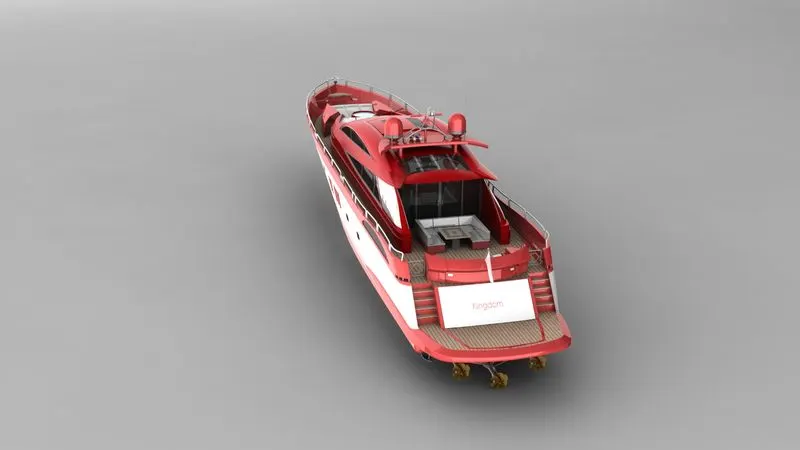
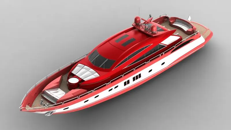
Red Variant:
Additional Views
Camera View
Isometric View
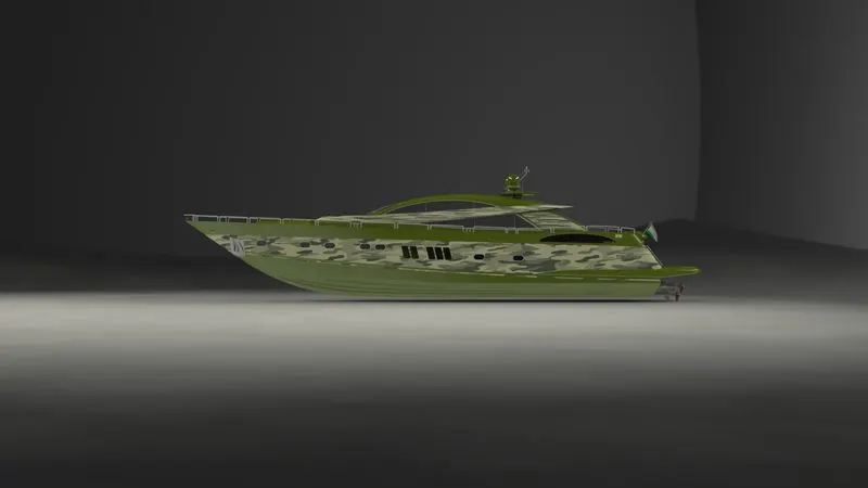
Military Variant:
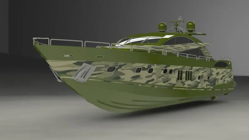
Additional Views
Camera View
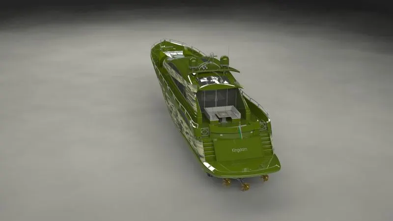
Side View
Business Variant:
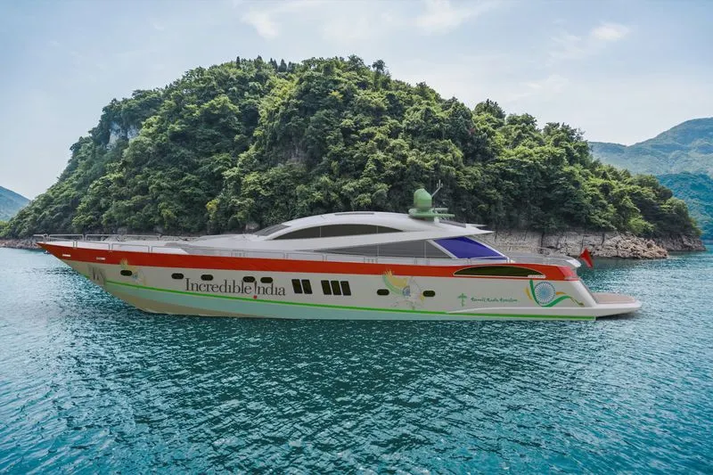
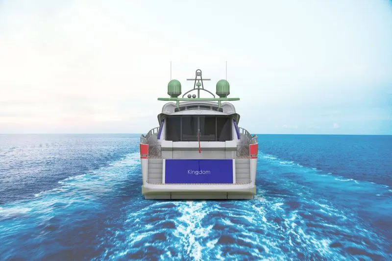
Additional Views
Side View
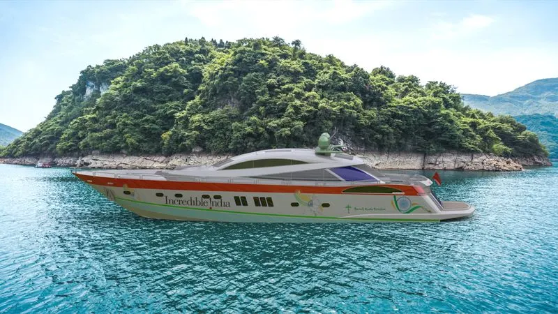
As I render these images its efficient to convey the purpose of the yacht in diiferent fields. And also these renders get a quick attention by its different appearance.
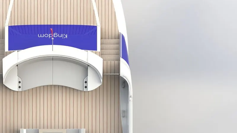
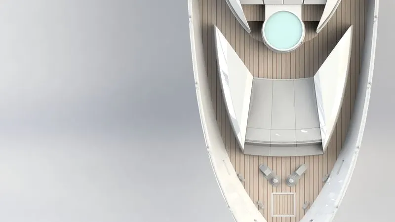
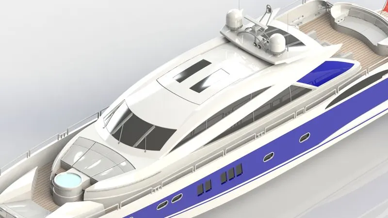
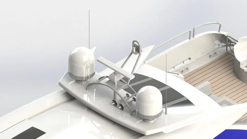
Apart from these renders, explaining the standards of the product we designed is more important next to the renders of the product as above.
So, I rendered some parts of the yacht to easily grab the attention that clearly explains the standard of the product.
That render images are as follows, which explains the features of the yacht.
Conclusion:
The Sunseeker Predator Yacht is successfully modeled in Solidworks. The parts are modeled using Sketch, features and surface tools and assembled together with assembly tools like mates. Then successfully rendered to get a good product design of Sunseeker Predator yacht using Photoview 360 add-in from Solidworks.
Project report and rendered images are attached in the following link:
https://drive.google.com/file/d/14c24zVHv7ZXiJcWeCHz5GvwvE-qoAS3c/view?usp=sharing