Hood design-Week 2
HOOD DESIGN FOR THE GIVEN STYLING SURFACE IN SIEMENS NX CAD:
INTRODUCTION:
- In British terminology, hood refers to a fabric cover over the passenger compsrtment of the car. It is known as the roof or top in the US. It is also known as bonnet in the commonwealth English.
- The hood gives us the access for the engine compartment, the trunk allows the access to the rear engine in some vehicles.
- In many motor vehicles built in the 1930s and 1940s, the resemblance to an actual hood or bonnet is clear when open and viewed head-on. The hood serves the similar purpose in todays cars too but no longer resembles the head covering.
- On front engined cars, the hood is hinged on front edge or rear edge in the rear engine cars; In the previous Ford car models the hood is split into two parts & it is hinged at the centre.
- Car hood is meant to protect the performance parts of the vehicle such as engine. One of the common type of damge occurs in the hood is in hinges. The hinges connects the hood with the car body & maintains the alignment of the axis.
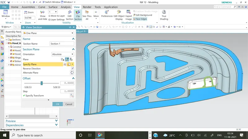
- Hood is consists of outer panel, inner panel having embosses, mastic points these type of reinforcements. Actually inner panel is acts like one of the reinforcement for the outer panel.
- The hood provides padestrian safety, safety for the engine components, as well as heat dissipation capacity & good styling for the passenger cars.
- Hoods are typically made out of the same material as the rest of the body work. This may include steel, aluminium, fiberglass or carbon fiber. However, some aftermarket companies produce replacements for steel hoods in fiberglass or carbon fiber to make the vehicle lighter.
- Hood design is the important part of the BIW stage. After this the joining process of parts before the undercoating & painting parts of the vehicles.
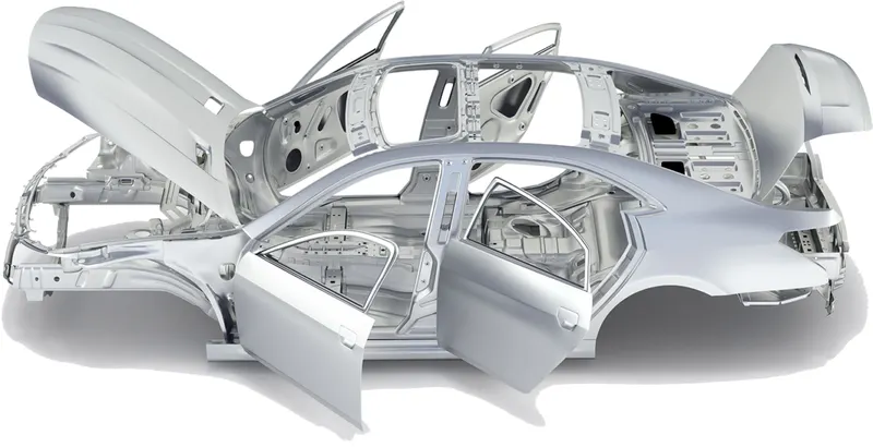
Fig:1_BIW design Structure of car model
TYPES OF HOOD:
The hoods are of two types according to its styling:
1] Inlaid Hood
2] Wrap around Hood
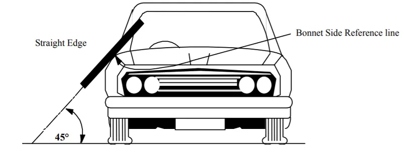
Fig:2_ Bonnet Side Reference Line
These two types of hood are differentiated by its vertical distance from endpoints of hood to the datum ground reference plane.
INLAID HOOD
- Inlaid hood are set inside the endpoints or end contour of car & lie onto the fender of the car. It covers less area than wrap around hood so it is light in weight. It has border defects,geometric discontinuties & less stifffness as compared to wrap around hood.
- These type of hoods having less impact area so it provides less pedestrian safety than wrap around hood. The hood are light in weight as compared to other body parts of the car so it creates less impact to the pedestrian than other area of the vehicles.
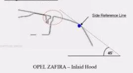

Fig:3.1_Inlaid hood geometrical presentation & car model
WRAP-AROUND HOOD
- Wrap around hoods are the end points or end contour of a car body lies on the hood. The distance between the end points of hood to the datum ground plane is less than the inlaid hood.
- The wrap around hood provides more strength & durability as well as more pedestrian safety. It provides more surface area for contact at the hood when somebody gets impact of collision on car.
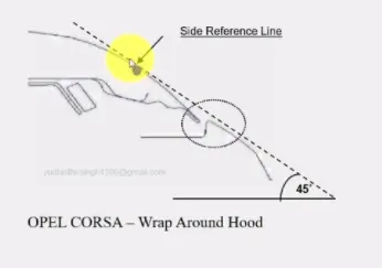

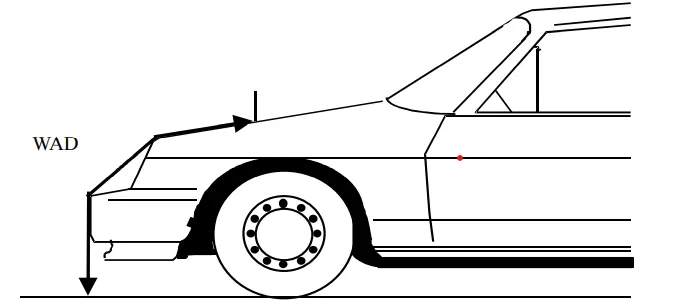
Fig:3.2_Wrap Around hood geometrical presentation & car model.
- Different types of hood according to their distance from datum plane :
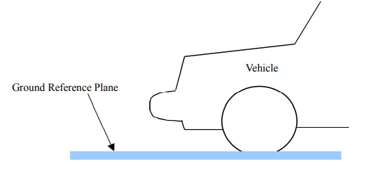
Fig:4_Ground Reference Plane or datum plane
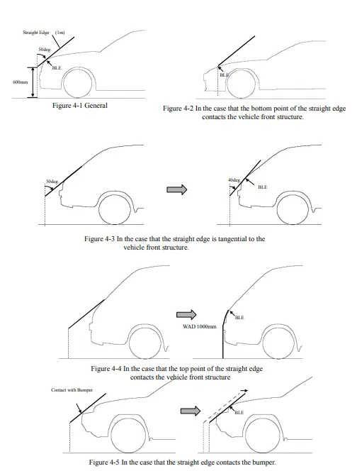
Fig:4.0_ Differentiation of hoods according to the reference line & different contatact areas, slope angles.
INPUTS REQUIRED FOR HOOD DESIGN:
Pedestrian safety, occupant safety, vehicle quality, styling, Manufacturability of component, NVH, Gas stay mounting, Latch & striker locations, Hinge axis, deformable brackets.
Pedestrian Safety:
- In todays scenario hood engineer is a really important part of the design aspect of a car due to various norms about the pedestrian safety.
- A designer focuses on the impact points of the pedestrian & the car at the time of any unwanted collision.
- The lower limbs of the pedestrian should come into contact to the extended part of the wrap around hood & the head or upper body of child or adult should get impact of light weight wide part of the hood.
- Different impact positions of different height people mentioned in the below image which comprised the thing that the head injuries should be restricted.
- Set the impact points on the light weight hood which has more capacity to absorb energy & get deformed at the time of sudden impacts rather than stiff hood & windshields.
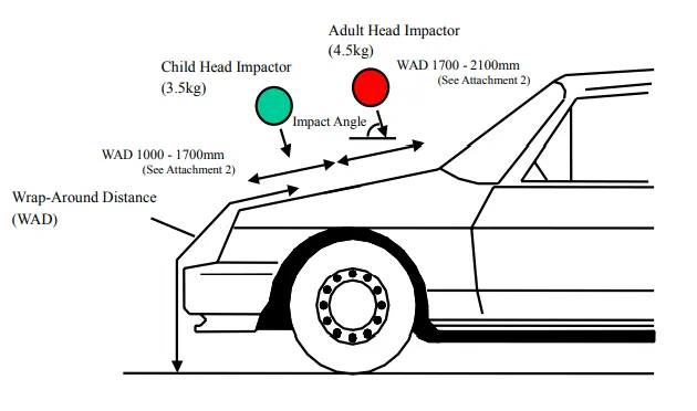
Fig:5.1_Different impact zones based on wrap around distance.
Fig:5.2_Impact simulator of human body on energy absorbent hood.
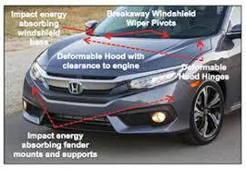
Fig:5.3_Real model car impact areas explaination
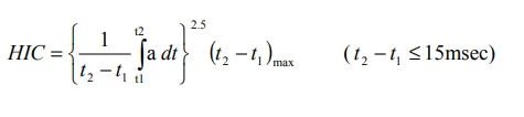
- HIC (Head Injury Criteria), defined by the following formula, should not be exceeded by 1,000 on two-thirds or more of the test area. On the remaining area, HIC should not be exceeded by 2,000.
Occupant Safety:
- The inner panel should have embossed areas & sufficient pierced areas which can diverge or transmit the force away from the occupants or passengers of the cars.
- The impact forces should transmit into wider areas which can dilute its intensity, the vibrations should be damped & should not attain any resonance conditions.
Manufacturability:
- Piercing, blanking, embossing, hemming these are the sheet metal operations are involved in the manufacturing of a hood of a car.
- Mastic sealants are used to join the inner & outer panel as well as reinforcements rather than spot welding process which creates the bad aesthetic of car.
- The mastic sealant is spread on panel in the dots pattern. The mastic points having spread or expansion area around 80 mm. After the heat treatment the mastics forms a spongy nature.
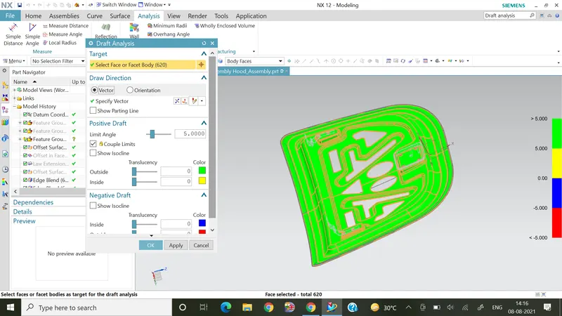
- Considering the stamping operation the draft angle should be maintained below 10 degree for the tooling direction.
- In the blanking operation the pierced components are used & the remaining sheet metal is used as a workpiece for the further operations.
- The hemming should be provided with the front & rear relief for manufacturing.The rolled edges reinforces the edges, removes burrs, sharp edges, packing for the inner panel & it improves the appearance, handling, packing.
NVH:
- Noise, Vibration, Harshness (NVH), also known as noise and vibration, is the study and modification of the noise and vibration characteristics of vehicles, particularly cars and trucks.
- These parameters of testing should be taken into consideration at the time of design of hood.
- Our complete NVH testing and NVH analysis solutions are ideal for optimizing noise and vibration of the vehicles, such as reduction, design, and quality assurance of the interior and exterior noise.
Gas Stay Mountings:
- Gas struts, also known as gas springs, provide direct support for safely lifting, positioning, lowering and counterbalancing weights.
- They offer the versatility of a wide range of forces, simple mounting, compact size, speed‐controlled damping, and cushioned end motion, combined with a flat force curve.
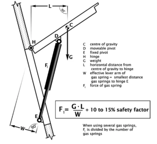
Fig:6_Gas stay mounting formulation
- Always install after painting, welding etc.
- The gas strut should always be fitted with the piston pointing down.
- Temperature range -30°C to +80°C.
- Use suitable end fittings and angle joints to avoid coupling jamming.
- Gas strut are maintenance free, do not grease or lubricate shaft.
- Install without twisting.
- Avoid lateral forces.
- Protect piston against dirt, paint or damage.
- Output forces will vary approximately 4% for every 10C change in temperature.
DESIGN METHODOLOGY:
Objectives:
- Our objective is to design hood using outer panel provided by styling team.
- Designing of hood inner panel, outer panel, hinges, latch & striker by taking into consideration the rules & regulation provided by the IHRA.
- we should design by taking into consideration of feasibility, manufacturability & aesthetics.
Design Input Data:
- Outer panel thickness = 0.75 mm
- Inner panel thickness = 0.75 mm
- Reinforcement thickness= 1.5 mm
- front & rear relief
- Hemming dimensions.
- Master section that consist of dimensional values of embossing, blent radii, width, flange clearances etc.
Fig:7_Master Sketch
Design Process:
- Most important parameters for design considerations are pedestrian, occupant safety, embosses, mastic points, blanking cutouts for the divergence & transmission of the impact forces onto the hinges.
- As per the master section initially we have to create different flanges of 2 mm, 4 mm, 25 mm using offset curve in face feature.
- The various commands like offset curve in face, face blend, edge blend, trim sheet, trim & extend these are the few surfacing commands being used to create the required hood shape.
- The datum plane, offset plane at distance, offset CSYS, datum CSYS, sketching, project sketch, fillet these some basic sketching tools are utilised to create required sketches.
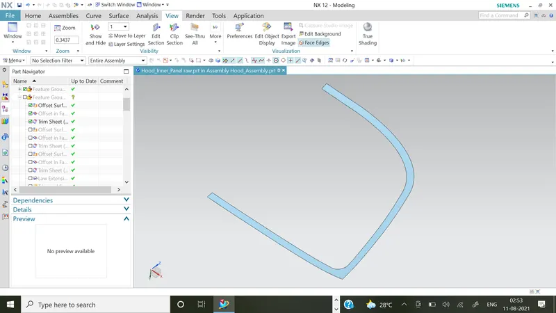
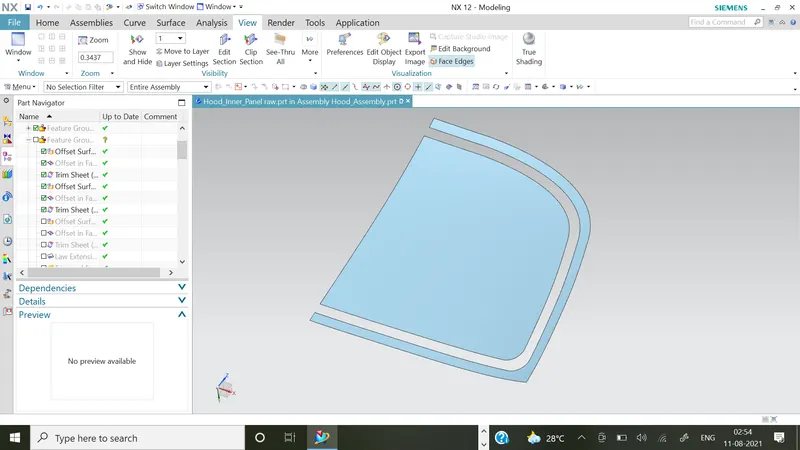
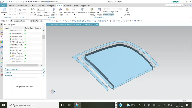
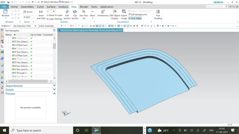
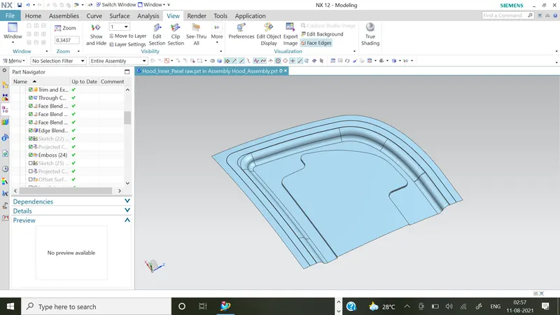
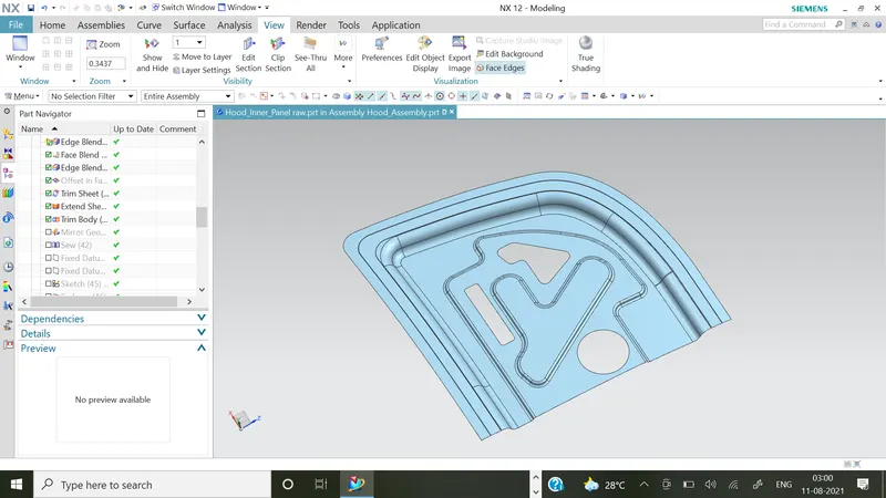
- The embosses, cutouts & blends are provided to minimise the weight of the hood & provision for the reinforcement between the outer & inner panel of the hood.
- The areas are provided for mastic sealant applications & viper fluid flow.
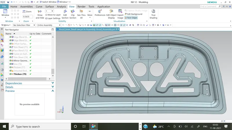
- Some thickness limitations are maintained for the optimum structure.
- The inner & outer panel thickness should be maintained 0.75 mm & the reinforcement should be maintained upto 1.5 mm.
- The clearance of 5 mm is provied between the outer panel & reinforcements.
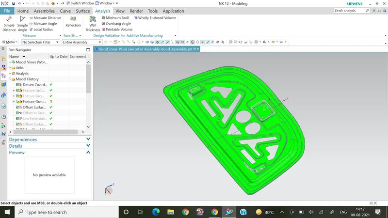
- The draft analysis performed which shows its manufacturability by using colors green, yellow, blue, red in the decresing order.
Outer Panel :
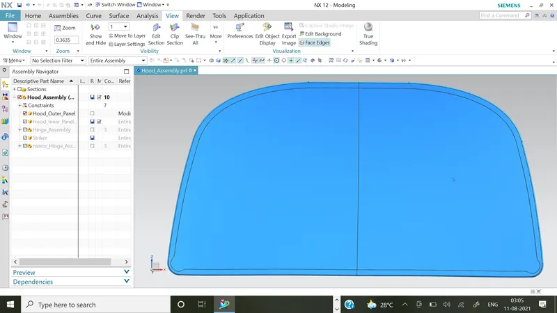
- The hood outer panel is designed using the outer panel provide by the styling team.
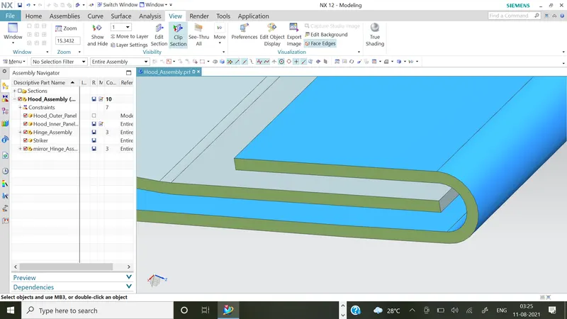
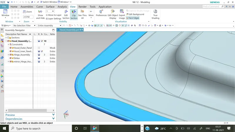
- The rear & front reliefs are provided for the hamming operation.
- In the hemming operation the clearance of 0.2 mm is provided for the adhesives layering for joining with the inner panel.
Assembly of Hood:
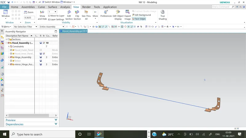
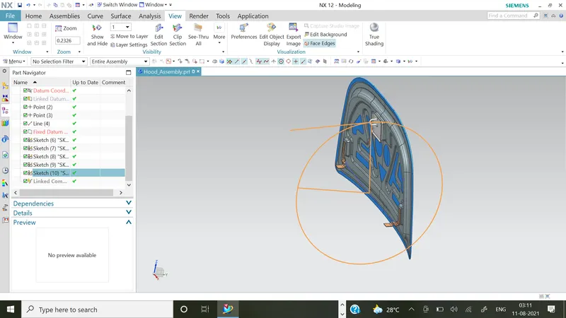
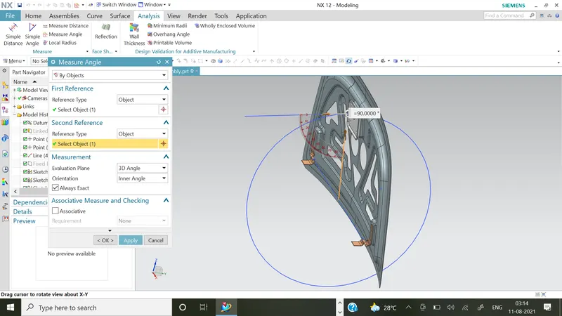
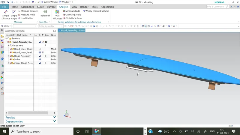
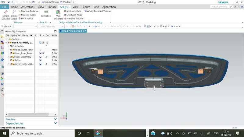
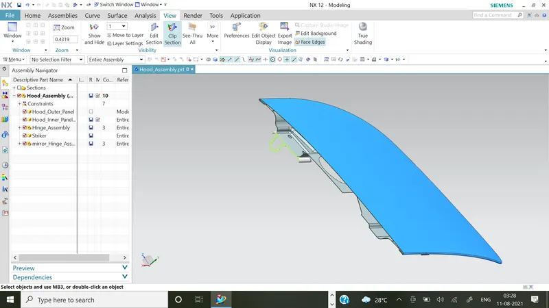
- The points are taken on centre of spheres of hinges & one line is joined between those two points to keep the hinges in same alignment.
- The circle is drawn by taking the centre of hinges alignment line upto the striker position.
- The tanget line of circle & the line drawn from striker is aligned by taking prefer touch constraint.
- In this way we can fix the opening & closing path of hood using this path constraint to the striker & hinges alignments.
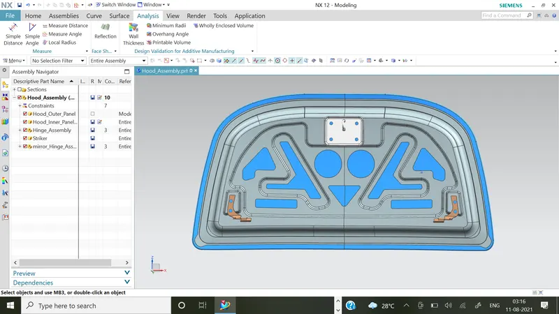
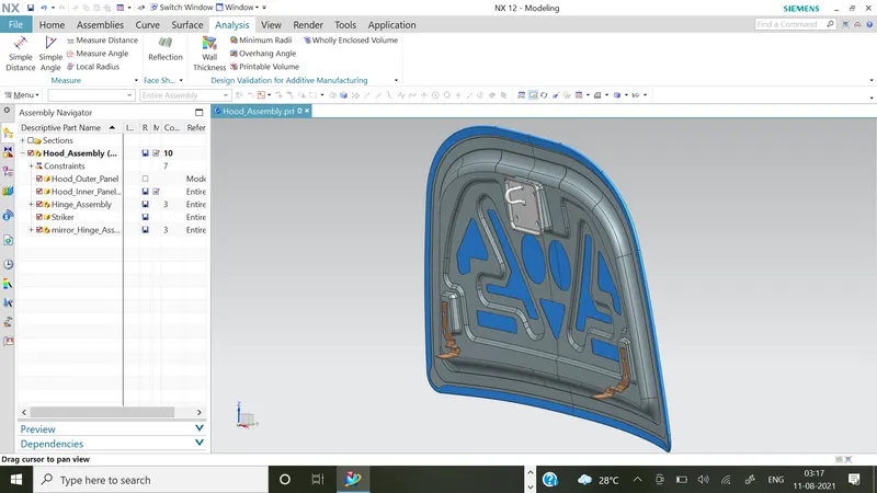
- The material allocation & edit object display is used for allocating color, material to the components.

Conclusion:
- The Inner Panel hood design is completed by using the given parameters such as thickness, clearance, embosses, cutouts, reinforcements, face blend, edge blend.
- The sketching is completed using on offset curve on face, project curve, check discontinuties in the geometry like these parameters are used.
- The tooling angle, draft analysis, clearances & reliefs are used to check the manufacturability of the designs.
- The hinges alignments, latch & striker path are used for proper alignment & proper assembly of the outer & inner panel with hinges, latch & striker.
- The overall project is completed by using the Siemens NX CAD & learnt to complete using CATIA V5.