Roof challenge
AIM:To design roof of car with roof rails & perform heat distortion, snow load analysis, section modulus inertia analysis, draft analysis.
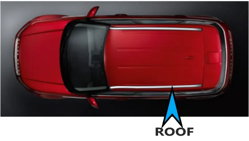
FIG_1: ROOF OF A CAR.
OBJECTIVE :
- To design ditch area for outer panel of roof on given styling surface.
- To design Front & rear roof rail for roof.
- To design Bow roof rails & reinforcements.
- To examine heat distortion & snow load criteria.
- To Perform draft analysis on individual parts.
- To perform section modulus inertia calculation.
INTRODUCTION :
- The design process starts from the need of the customers.
- According to the demand of the customer & rules of the automotive society we have to sketch or set the parameters.
- Afterwards we have to consider design for manufacturing & assembly (DFMA) parameters.
- Heat distortion analysis, snow load analysis, section modulus inertia analysis, draft analysis are considered for given design & do corrections to meet the requirements.
- An automobile roof or car top is the portion of an automobile that sits above the passenger compartment, protecting the vehicle occupants from sun, wind, rain, and other external elements.
- On the front side of the roof we have to place wind shield glass & on the rear side we have to place backdoor or rear hood.
- We have to perform calculations for heat treatment & snow load by plotting curves on the outer panel.
- Visibility criteria and head clearance will be considered according to different regions & rules.
REINFORCEMENTS :
- The reinforcements like roof rails are provided for making the roof stronger & should withstand with various loads such as snow, luggage, etc.
- In these reinforcements the front & rear roof rails, Bow roofs are involved to provide basic structure for the positioning of roof, wind shield & backdoor.
- Different joining or welding processes are involved in this positioning of the assembly.
PARTS INVOLVED IN ROOF ASSEMBLY:
- ROOF OUTER PANEL WITH DITCH AREA
- FONT ROOF RAIL
- REAR ROOF RAIL
- BOW ROOF RAIL L1 & R1
- CENTRE REINFORCEMENT
- CENTRE BOW ROOF RAIL
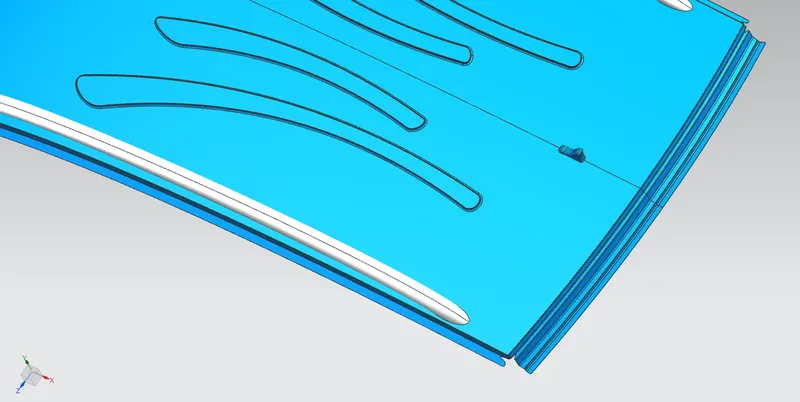
FIG_2: REAR DITCH AREA OF OUTER ROOF PANEL
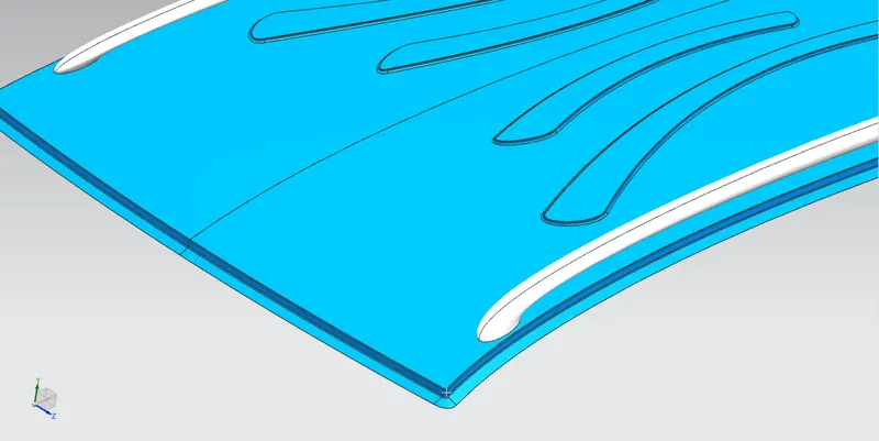
FIG_3: FRONT DITCH AREA OF OUTER ROOF PANEL
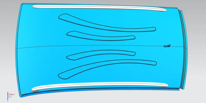
FIG_4: OUTER ROOF PANEL TOP VIEW
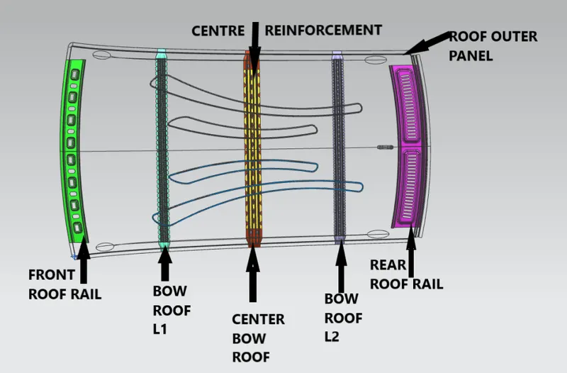
Fig_5: Components of Roof Assembly
FRONT ROOF RAIL:
- In the front roof rail design the wind shield positioning & visibility of driver as well as head space of the driver is considered.
- The front side flange is joined with spot welding & rear flange is joined with roof using mastics.
- Front Roof Rail is designed using the given master sketch & tool opening angle is only 3 degrees.
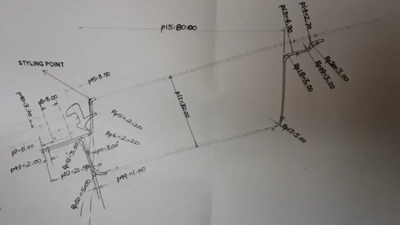
FIG_6: MASTER SKETCH OF FRONT ROOF RAIL
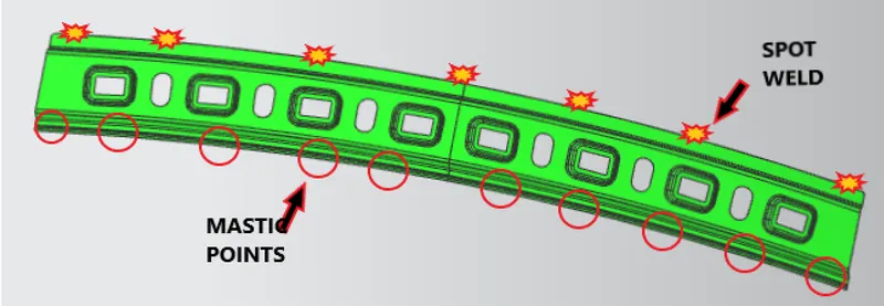
FIG_7: FRONT ROOF RAIL
REAR ROOF RAIL:
- Rear roof rail is designed for positioning the backdoor on the rear flange.
- The rear roof rail front flange is joined by using mastics to the outer panel.
- The rear flange is joined using spot weld with outer panel.
- The rear roof panel is designed using the given master sketch of rear roof panel.
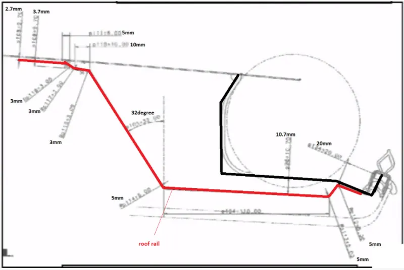
FIG_8: MASTER SKETCH OF REAR ROOF RAIL
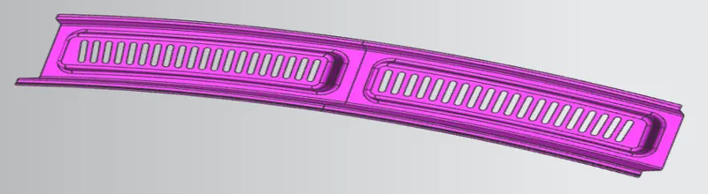
FIG_9: REAR ROOF RAIL
CENTRAL ROOF RAIL & REINFORCEMENT:
- Centre roof rail is positioned at the centre of the roof.
- It is wider than other bow roof rails because it bears the most of the load of roof.
- To strengthen the centre bow roof rail the reinforcement is provided.
- The reinforcement is joined with mastics to the outer panel
- The reinforcement & centre roof rail is spot welded.

FIG_10: REINFORCEMENT POSITION ON CENTRE BOW ROOF RAIL

FIG_11: CENTRE BOW ROOF RAIL
BOW ROOFS:
- Bow roofs are given to improve torsional stiffness and load bearing capacity of the roof structure.
- We can add number of bow roofs as per the length of the roof.
- we have used two bow roofs on left of the central bow roof & right of the central bow roof.

FIG_12: BOW ROOF RAIL L1

FIG_13: BOW ROOF RAIL R1
HEAT DISTORTION ANALYSIS:
- Heat distortion temperature study is really important in the domain of sheet metal analysis.
- At the elevated temperatures above the heat distortion temperature the sheet metals can't be used for structural applications.
- This heat distortion calculation shows at what temperature on fixed load the sheet metal will start soften & deformations will be experienced.
- We will get the result on roof rails postioning after the heat distortion calculations.
- We can strengthen the roof by rightly positioned the roof rails by getting optimum values from calculations.
- Bow–roof prediction Formula :
W = [1.73 x 10^(-3) x L] + [1.85 x 10^(-8) x (R^2)/t] + [ 1.10x10^(-3) x l] - 2.68
- Judgement Condition : OK< 2.7> 3.1
Where
- L = Roof Length in X-Direction[mm](Roof dimension in 0-Y)
- R = Roof curvature
R = 2(Rx*Ry)/(Rx+Ry)
- Rx = X curvature
- Ry = Y curvature
- t = Roof plate thickness [mm]
- l = Bow Roof Span [mm]
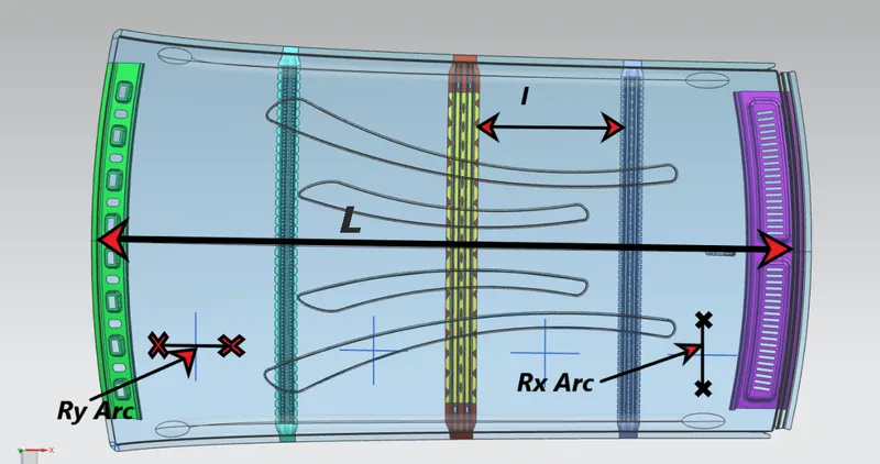
FIG_14: NOTATIONS OF PARAMETERS FOR HEAT DISTORTION CALCULATION
Procedure for calculation of heat distortion criteria:
- we have created 0-Y line offset it through -3Y & then created 100 mm right & left side of -3Y.
- The vertical lines are plotted between the roof rails at midpoints.
- The vertical lines are creted by offsetting 100 mm right or left.
- Then we marked the intersection points & projected on the outer roof panel.
- The three point arcs are used to create curves on outer panel.
- The Local radius command is used for Rx & Ry calculation.
- The all values are measured through projected sketch & used in excel sheet.
- The all required values & formulae are feeded in excel sheet for given calculations.
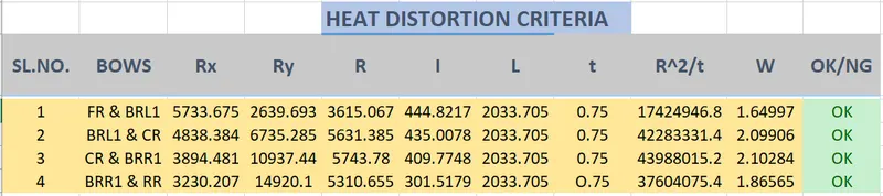
- We can conclude that positioning of roof rail is OK for heat distortion analysis because all values lies between less than 2.7 & not greater than 3.1.
SNOW LOAD ANALYSIS:
- This analysis is conducted to observe the behaviour of our roof desiogn under snow load.
- Initially deformation is observed due to the snow load in the roof.
- But it should be elastic deformation not plastic deformation is the important thing in this analysis.
- The dent should regain its original position after removal of snow
- We have to make offset lines at 0-Y 100 mm offset on both sides instead of -3Y.
- We have to follow the same steps as per heat distortion in this analysis too.
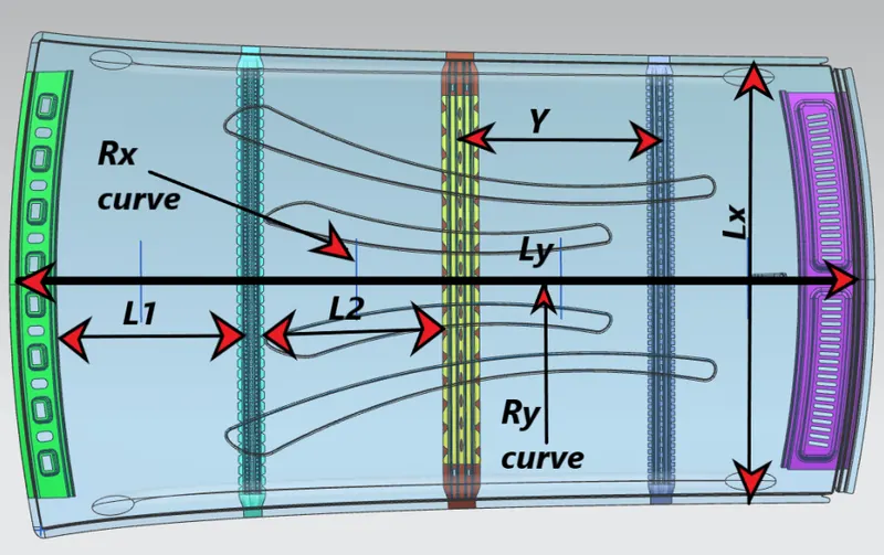
FIG_14: NOTATIONS OF PARAMETERS FOR SNOW LOAD CALCULATION
Snow load Prediction formula
Qr = [Iy x t2] / [α x s x [(Rx + Ry)/2]2 x 10-8]
- Note: The Qr value given over here is correct. There was a typo error in the formula given in the video.
Where
- α = My x Lx2 x 10-12 , My = Y(Ly-Y)
- Judgement condition = Qr ≥ 3.1
250 ≤ s ≤ 380
- t = Roof plate thickness [mm]
- Ly = Distance between the front and rear roof Rails on the Vehicle along with 0Y[mm]
Length of Roof panel with the center point between Roof rail Front /Rear as the front and rear reference point.
- Lx = Distance between the Left and Right end of the roof on the Roof BOW [mm]
Width of the roof panel exposed on the surface.
- Y = Distance front Front Roof Rail to Roof BOW[mm]
- s = Distance for which Roof BOW bears divided load [mm]
s = L1/2 + L2/2
- Iy = Geometrical moment of inertia of Roof BOW (Y cross-section )[mm4]
- Rx = Lateral direction curvature radius of roof panel Y cross-section on Roof BOW [mm]
Roof panel curvature Radius of the Length Lx in Front view
- Ry = Longitudinal Direction curvature radius of the Roof panel X cross-section on Roof BOW [mm]
Roof panel X curvature radius of length s in Side view

- From the above calculations we can observe Qr > 3.1 so the positioning is OK for snow load.
SECTION MODULUS:
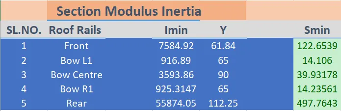
- It is the ratio of second moment of area and distance from neutral axis to the extreme fiber.
- It shows the stiffness of the given member.
- Section modulus is a geometric property of cross-section used in the design of flexural members or beams.
- The stress in the outermost section of the beam is calculated by section modulli method.
- There are two types of section moduli, the elastic section modulus and the plastic section modulus.
- The elastic section modulus is defined as,
S = I / y
where I = Second moment of inertia
y = Distance from the neutral axis to extreme fibre
- The unit of sectional modulus is cubic millimeter.
- The bodies having more shear modulus are tougher & can withstand more load.
Section Modulus Calculation of ROOF RAILS:
METHODOLOGY:
- Create a datum plane at the centre of the Roof Rails.
- Use the Intersection Curve option.
- Project the 2D sketch From given 3D Sketch
- Use trim option & studio spline option to get required closed geometry.
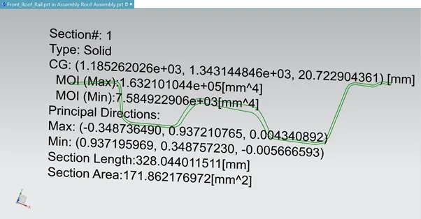
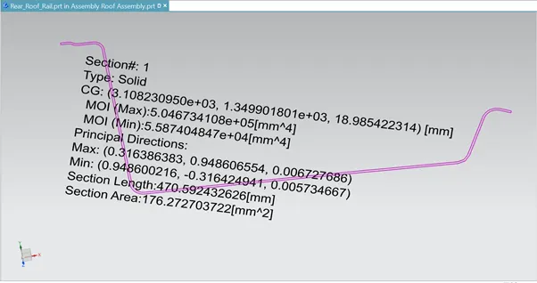
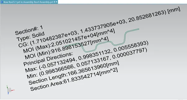
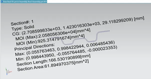
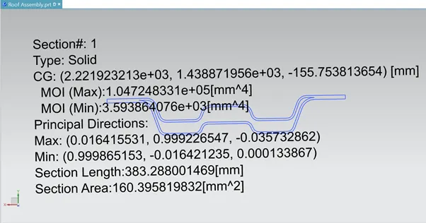
- Apply section inertia modulus command to get section modulus for solid section.
- Section modulus inertia of front roof rail:
- Section modulus inertia of rear roof rail:
- Section modulus inertia of Bow roof rail L1:
- Section modulus inertia of Bow roof rail R1:
- Section modulus inertia of Central Bow roof & Reinforcement:
- Tabular calculation of section modulus inertia:
DRAFT ANALYSIS:
- Draft analysis helps to judge the product we designed will be easily removable from dies.
- The results of the draft analysis is shown through colors green, blue, yellow, red.
- In the given analysis toooling opening angle is mentioned 3 degree or more.
- The green color will predict the all tooling direction having positive draft angle more than 3 degrees.
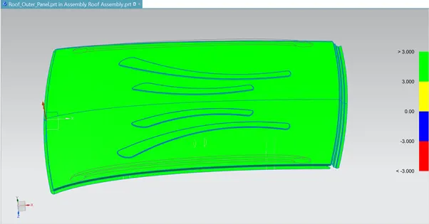
FIG_15: Draft analysis for roof outer panel
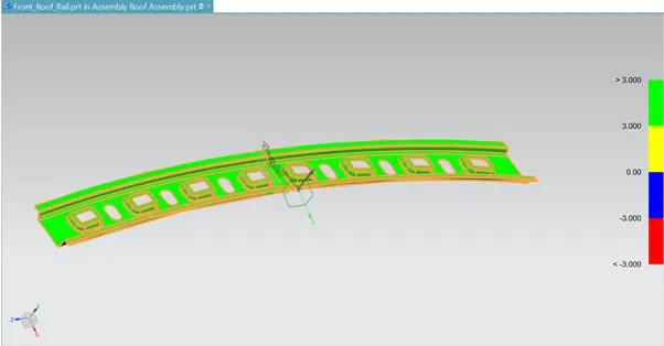
FIG_16: Draft analysis for Front Roof Rail
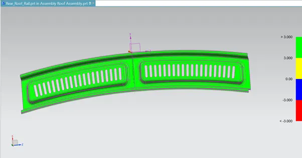
FIG_17: Draft analysis for Rear Roof Rail
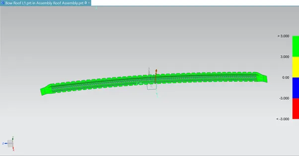
FIG_18: Draft analysis for Bow Roof Rail L1
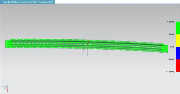
FIG_19: Draft analysis for Bow Roof Rail R1
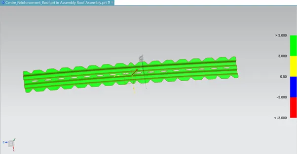
FIG_20: Draft analysis for Reinforcement
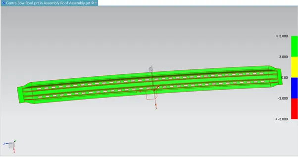
FIG_21: Draft analysis for Centre Bow Roof Rail
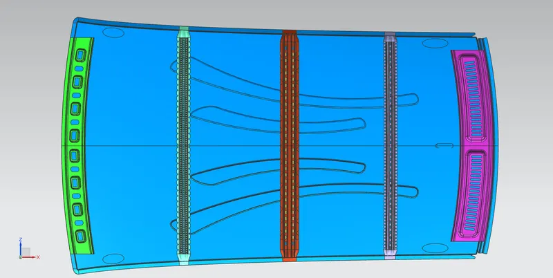
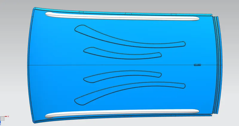
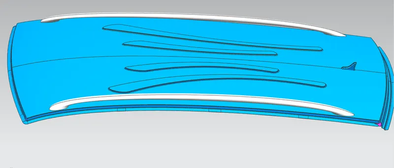
ROOF OVERVIEW:
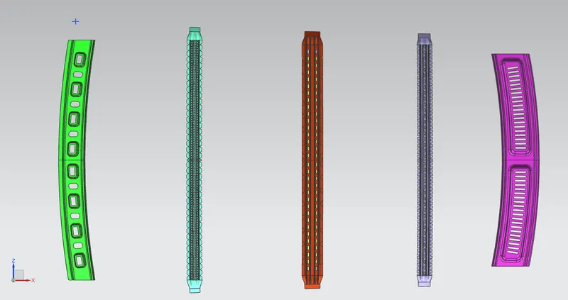
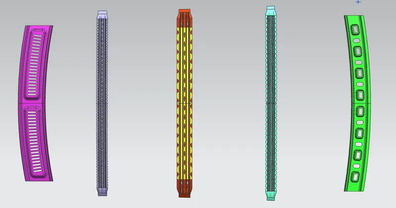
Conclusion:
- As above we have designed all essential parts of the roof assembly.
- We have examined all criteria are fulfilled by the above design.
- We have good results for Heat distortion & snow load criterias.
- The Roof Rails positioning is also better too bear all loading conditions.
- We have provided embosses on roof outer panel too improve its strenth.
- The all embosses & material removal is executed too improve stiffness & make it light weight.
- All parts having good results for draft analysis as well as sectional inertia analysis.
- In this way the roof design project is completed successfully.