DESIGN OF CAR HOOD
Design of Car Hood Assembly
- Objective: The aim of this project is to construct a well defined hood assembly by modeling the different parts needed in creation of our hood assembly that parts are hood inner & outer panel, hinge assembly, striker, etc.
1.0 Introduction
What is a Hood? :
A car hood also referred to as a bonnet in some other countries is the hinged cover that rests over the engine of a front-engine vehicle. Its purpose is to provide access to the engine for repair and maintenance also to cover the engine compartment and give an aesthetic look to the vehicle. A concealed latch is typically used to hold down the hood. On vehicles with an aftermarket hood and on racecars, hood pins may be used to hold down the car hood. Hoods sometimes also contain a hood scoop, wiper jets, power bulge, and/or hood ornament. Car hoods are typically constructed from steel and sometimes from aluminum. Aftermarket car hoods may be constructed from various other materials, including carbon fiber, fiberglass, or dry carbon. The hood design may vary from one make and model to another, including SUV, MUV, Sedan, Hatchback, or heavy vehicles.
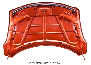
Fig.1.1 Inner side view of Car Hood Fig.1.2 Outer view of Car Hood
Fig 1.3 Complete hood of ford Shelby cobra
2.0 Design Considerations in Hood
While designing a hood several design parameters are to consider such as the opening angle of the hood, Support system for the hood, Pedestrian safety rules, etc.
2.1 Hood head zone for striker locking: While designing the hood this parameter should be taken into consideration because when we open the hood to get access to the engine compartment to perform any operation while the hood is in open condition the minimum height of the hood should be such that it does not collide or hit to head of the person who is operating. So, the height of hood in open conditions should be more than the average height of humans in that region thereby no human gets hurt.
Following data should be used for deciding Hood head zone
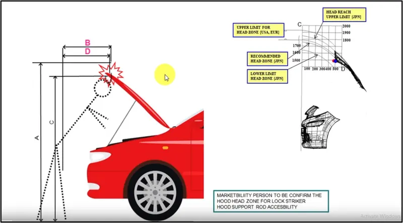
Fig 2.1 Hood Head Zone Selection Criteria
2.2 Hood Stay:
This is the support system for the hood as when we open hood we need it to rest to keep it in open position & this can be done by placing it over something or by providing support to it. While designing this one should keep in mind that the support system should be self-sustainable to take the load of the hood even if any external force is been applied on it due to wind or any other reason & it should facilitate easy opening and closing of hood.
This can be done by using two ways
1. Support Rod
2. Gas stay
Support Rod: It is a rod that accommodates itself easily inside the engine compartment and support the hood when we open it by attaching the rod in the hook provided inside the hood. Initial bends are been provided to the support rod to provide stiffness.
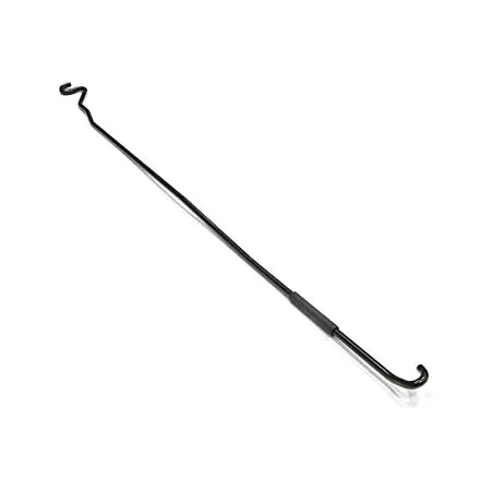
Fig 2.2 Hood support rod
Gas Stay: This type of apparatus is used in most heavy vehicles where the weight of the hood is more and it is difficult for a human being to open it conveniently. So, basically, a gas stay system uses gas-filled telescopic cylinders which only require an initial force to set it in motion.
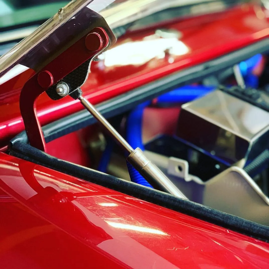
Fig 2.3 Hood Gas Stay
2.3 Pedestrian safety:
While designing the hood, it is vital to consider the safety of pedestrians as when your car hits the pedestrian during a crash, it is very important to study the areas over the hood where different body parts of pedestrians are going to hit. we should also take into account the average height of adults and children while designing our hood. So, whenever a new car is been launched, all these safety parameters are checked by taking a crash test and studying the data obtained from it to make changes accordingly to follow pedestrian safety.
Fig. 2.4 Euro-NCAP guideline for pedestrian safety
2.4 Mastic Data:
We know that the hood comprises two main parts: a hood inner panel and a hood outer panel. The hood inner panel is enclosed below the outer panel and thereby provides rigidity to the hood. When these parts are assembled to form a hood a small gap remains between these two parts as they are both metal parts this may lead to noise and vibrations when the vehicle is in running condition which is undesirable to avoid this mastic sealant is filled between this small gap.
Mastic sealant is a paste-like material that is applied on a surface and is hardened by heating.
Fig. shows the points where mastic sealant is to be applied
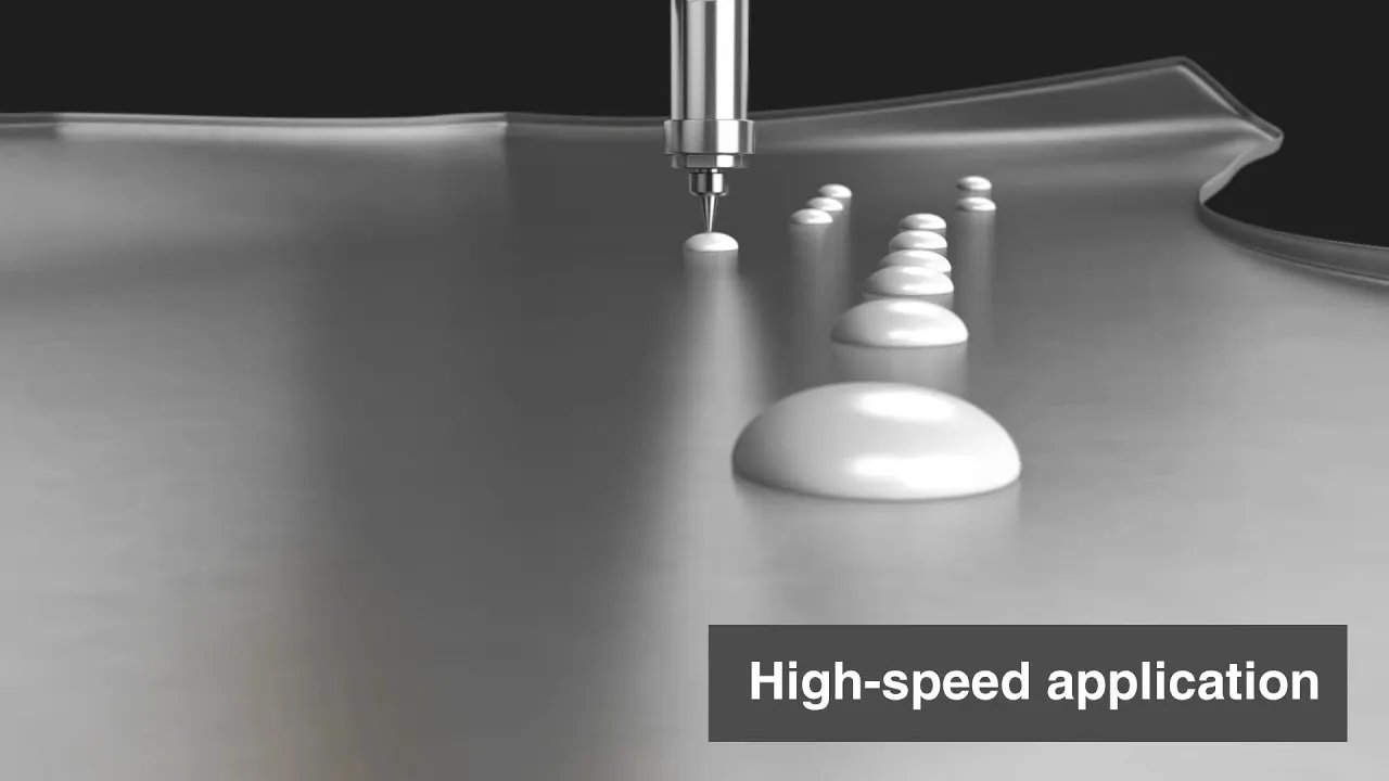
Fig. 2.5 Mastic sealant points
2.5 Force Distribution:
A good designer should always consider the safety parameters as a top priority, In the case of hood design, one should design the hood in such a manner that if the vehicle gets a frontal crash then all the forces must be distributed towards the hinge of the hood, as it is important to reduce the impact of the crash by diverting the force towards the hinges and thus safeguard the passengers in the vehicle.
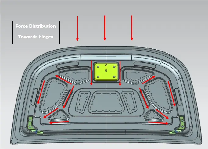
Fig. 2.6 Showing force distribution through hood
3.0 Hood assembly components:
Now let's have a brief discussion about how a hood assembly is done what are the main components involved in it. So, we know that any assembly consists of two or more parts joined together to form a complete product.
Hood also embodies several parts they are as follow:
1) Hood outer panel or skin of the hood
2) Hood inner panel
3) Hinge assembly
4) Striker
1) Hood outer panel:
This part of the hood acts as a covering or casing for all the other parts of hood which are enclosed inside this part. The outer surface of this part is provided with a good surface finish, painted with corrosion-resistant paint to prevent the inner parts from corrosion and also to give an aesthetic look to the car from the outside. This part forms the shape of our hood and it is given different styling and shapes to enhance the look & performance of the vehicle to reduce the forces exerted by air when the vehicle is in motion.
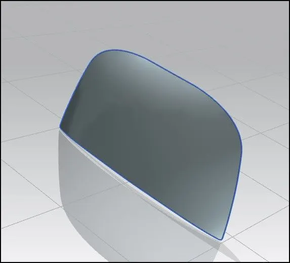
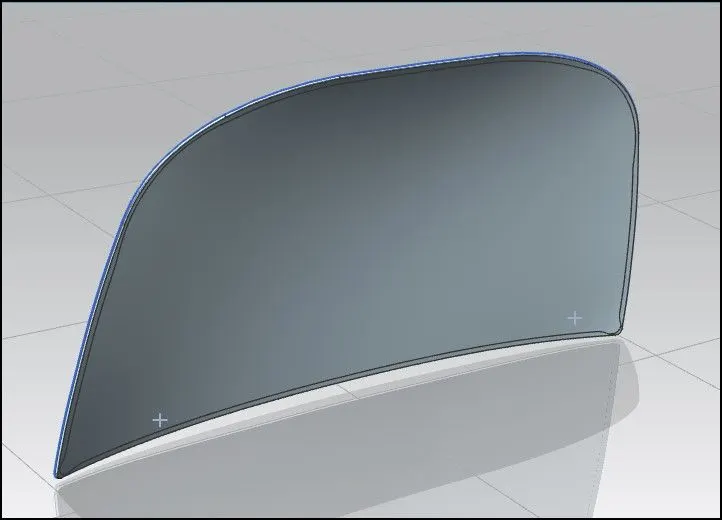
Fig. 3.0 Hood outer panel
2) Inner panel:
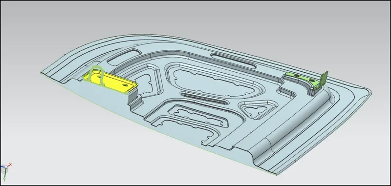
This part is enclosed in the outer panel it forms an integral part of the hood and provides rigidity to the hood, it is the part on which hinges, striker are to be fixed to make our hood fully functional it also consists of embossed sections for proper force distribution and mastic sealant points are also located on this part with reinforcement for hinge & striker. To reduce the weight of our hood some material is removed from the hood inner panel as shown below.
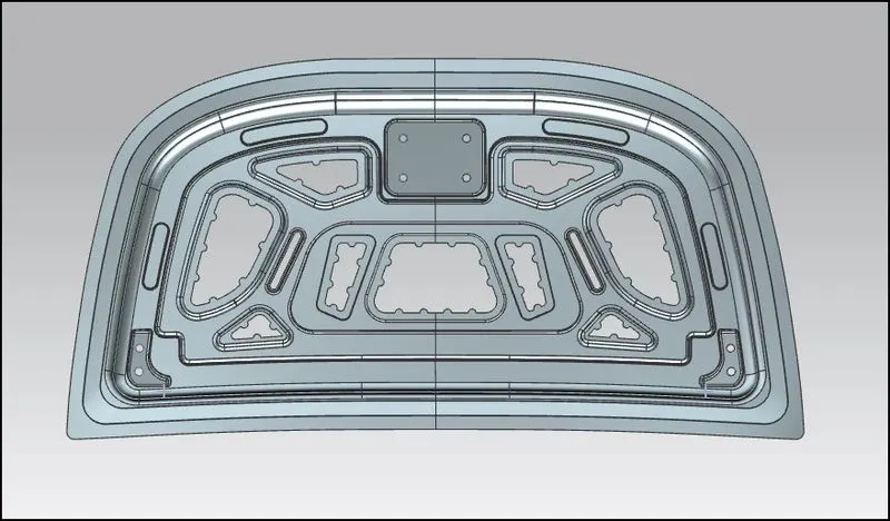
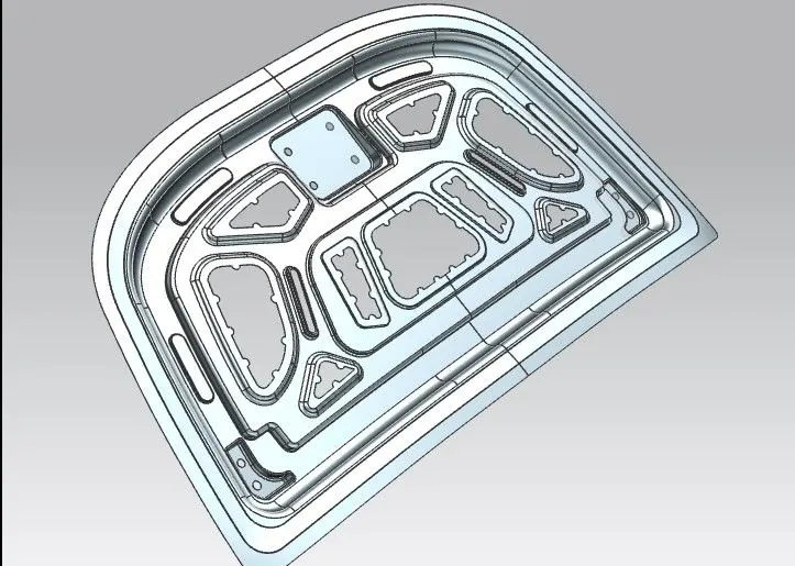
Fig. 3.1 Hood Inner panel
3) Hinge assembly:
It is an important part of our hood because by use of this part only we are able to open and closed our hood whenever required with ease. This part should be strong enough to take the load of the hood and also the forces which act upon the hood in case of crash. So, this part should be designed with utmost care that it should not fail during its operation.
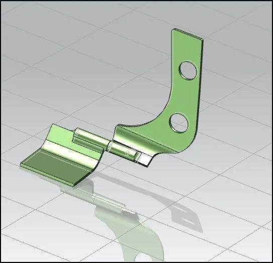
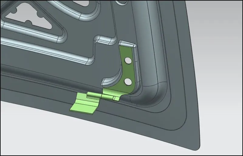
Fig. 3.2 Hinge assembly and its placement on hood inner panel
4) Striker:
This part is used for providing locking to the hood it consists of a latch-type mechanism and it is located on the inner panel of the hood to decide the position of our striker, the trajectory method is used with the help of this method we can easily locate our striker. This part holds our hood in closed condition unless it is being open by pulling the latch lever to open our hood.
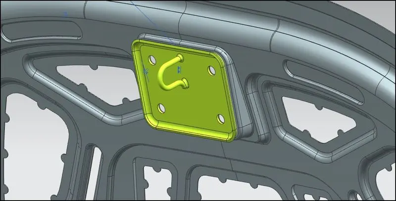
Fig.3.3 Striker
Now to start with our hood design some standard or master data is to be followed for deciding the dimensions of our hood such as thickness of inner and outer panel, heming data, etc.
4.0 Hood input data:
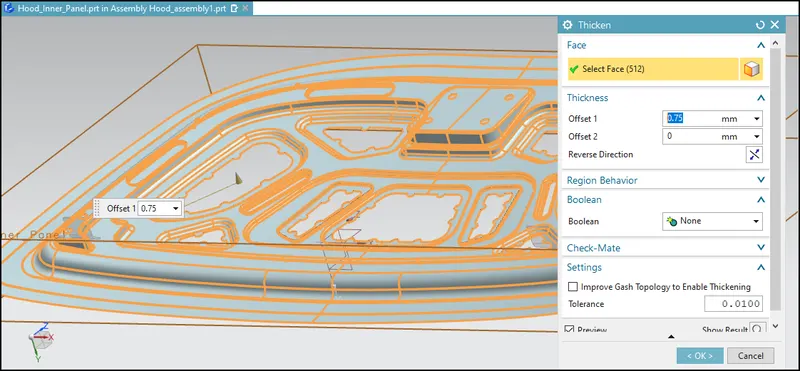
- Thickness of outer panel: 0.75mm
- Thickness of inner panel: 0.75mm
- Reinforcement thickness: 1.5mm
This thickness is to be followed throughout the hood design
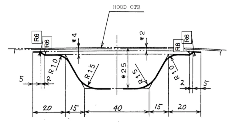
4.1 Master section:
This data is used for the design of our hood inner panel it gives all the information about the standard dimensions to be followed for the inner panel also information about radius values, maximum height of the hood inner panel from the top.
5.0 Manufacturing processes for production of hood inner & outer panel:
Hood inner & outer panels can be manufactured by performing forming operations on a thin metal sheet.
5.1 Deep Drawing:
Deep drawing is a sheet forming process in which a sheet metal blank is radially drawn into a forming die by the mechanical action of a punch. It is thus a shape transformation process with material retention. The process is considered "deep" drawing when the depth of the drawn part exceeds its diameter. This is achieved by redrawing the part through a series of dies. The flange region (sheet metal in the die shoulder area) experiences radial drawing stress and tangential compressive stress due to the material retention property. These compressive stresses result in flange wrinkles (wrinkles of the first order). Wrinkles can be prevented by using a blank holder, the function of which is to facilitate controlled material flow into the die radius.
Deep drawing processes are divided into three types:
- Deep drawing with tools
- Deep drawing with active means
- Deep drawing with active energy
In the automotive industry, deep drawing is usually carried out using rigid tools.
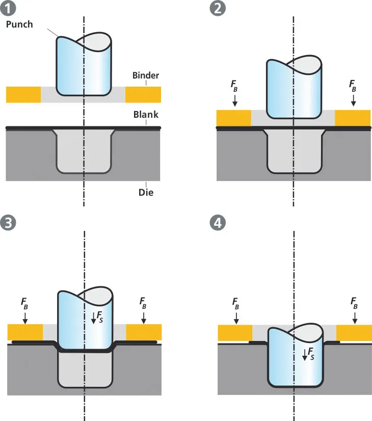
Illustration of the deep drawing process
The figure illustrates the deep drawing process. The rigid tools consist of a punch, die and binder. In deep drawing, the plate holder closes after the metal sheet blank has been inserted.
Next, the sheet is clamped between the die and the binder. This process slows down the flow of the sheet while it is being drawn and thereby prevents wrinkles from forming under the binder. The punch stretches the sheet over the die radius and forms it in the die. The amount of punch force necessary for forming is thereby continually increased up to the lower dead center of the punch.
Whereas in pure deep drawing there is no reduction of sheet metal thickness, forming is achieved in stretch forming purely as a result of a decrease in sheet metal thickness. Stretch forming is extensively used for the forming of only slightly curved parts with low depth of draw (e.g. roofs, doors).
When drawing complex car body parts in practice, there is usually a combination of stretch and deep drawing involved. It is necessary that the sheet metal is stretched as well as possible without reaching the material’s limits (e.g. splits, wrinkles).
There are approximately 300 to 400 sheet metal parts that fit together to form the body of a car. In order to manufacture high-quality sheet metal parts optimally for their particular use, specialized software simulates the complete deep drawing process.
5.2 Heming:
Hemming is a forming operation in which the edges of the sheet are folded or folded over another part in order to achieve a tight fit. Normally hemming operations are used to connect parts together, to improve the appearance of a part and to reinforce part edges.
In car part production, hemming is used in assembly as a secondary operation after deep drawing, trimming and flanging operations to join two sheet metal parts (outer and inner) together. Typical parts for this type of assembly are hoods, doors, trunk lids and fenders.
The accuracy of the hemming operation is very important since it affects the appearance of the surface and surface quality. Material deformations, which occur during the hemming process, can lead to dimensional variations and other defects in parts. Typical hemming defects are splits or wrinkles in the flange, material overlaps in the corner areas or material roll-in. This is why it is important to use simulation tools in order to, on the one hand, better understand the hemming process and, on the other hand, significantly reduce the number of “trial and error” loops during tryout and production.
There are two types of heming process use:
a) Conventional die Heming
b) Roll Heming
a) Conventional die heming:
Conventional die hemming is suitable for mass production. In die hemming, the flange is folded over the entire length with a hemming tool. Normally the actual hemming is a result of a forming operation in which the flange is formed with a hemming tool after the drawing and trimming operations have been completed. Production plants for conventional die hemming are very expensive, but the cycle times are very low.
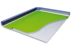
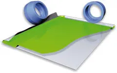
Fig. 5.2 Conventional die heming process, flange Fig. 5.3 Roll heming process, flanges are folded with the help of rollers guided by
is folded over entire length with a heming tool industrial robot
b) Roll Heming:
Roll hemming is carried out incrementally with a hemming roller. An industrial robot guides the hemming roller and forms the flange. Roll hemming operation can also be divided into several pre-hemming and final hemming process steps. Roll hemming is very flexible to use and tool costs are significantly lower as compared to those of conventional die hemming. However, the cycle times are much higher since the hemming is realized using a hemming roller that follows a defined path.
Now, let us discuss how to model the hood using NX-CAD software, which features to be used. NX-CAD provides several surface features and advanced tools for modeling of complex parts they are as follow:
6.0 Commands used in modeling of Hood assembly
To start with our modeling first understand what we have to model what are the end requirements of the product and then move on further.
In the case of our hood, we will first critically examine the given data for our hood i.e the required thickness the dimensions to be followed.
Following commands are used in hood modeling
- Offset surface: This feature is available in surface modeling commands by using this we can offset the surface by required distance along a vector or selected plane.
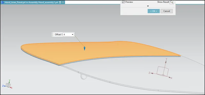
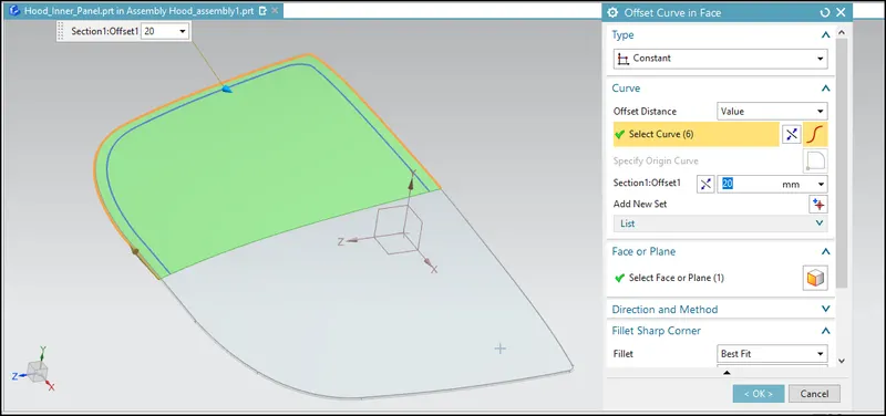
- Offset curve in face: This feature is very useful as it allows us to offset the curves or edges on the face by required distance & in the required direction.
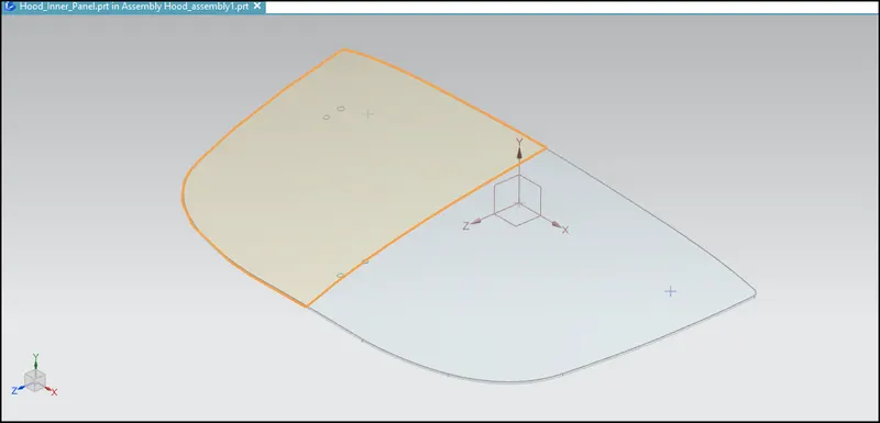
- Trim body: These features enable us to cut off the portion from a solid body or surface body to be removed along a vector or along a plane.
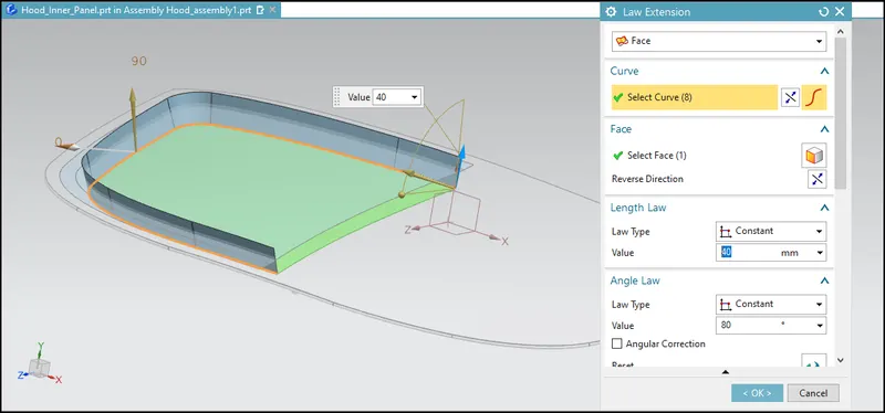
- Law of extension:
This feature extends the selected curve or edges of a base in a controlled manner i.e we can change the length, angle of the extended surface and also the law with which it gets extended.
- Through Curves:
This feature enables to create a body through multiple selected sections by following the path of form by sections and thus create a body underlying between this section.

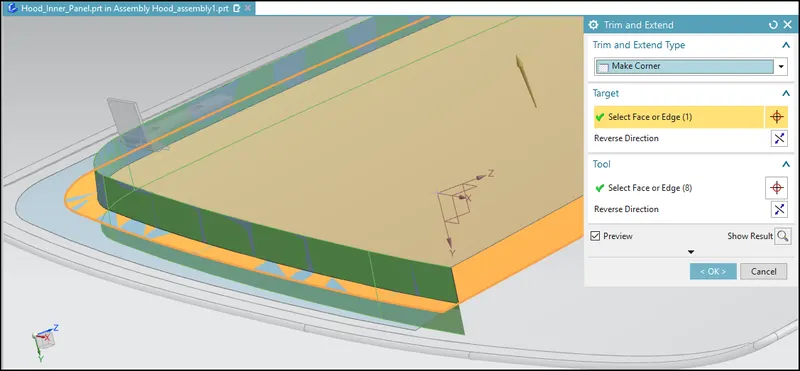
- Trim & Extend:
This feature extends or trims the set of faces & edges which get intersected with another set of faces & edges as shown below. by using this feature one can easily create emboss surface without using emboss feature tool in NX-CAD.
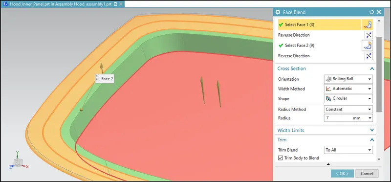
- Face Blend:
Adds tangent blend faces between a selected set of faces, the shape of blend face may be circular, conic, or law controlled. There are various types of face blends such as two face blend, three face blend it depends on our application to use the type of blend.
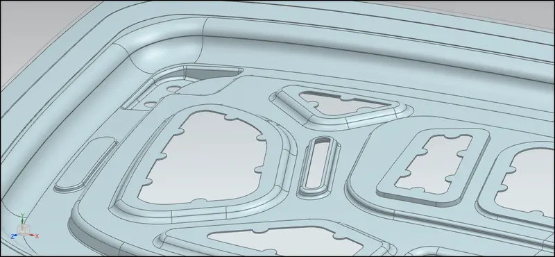
- Emboss:
Modifies a body faces by projecting a section along vector direction, with options such as end-cap location or shape for the emboss created.
- Mirror Assembly:
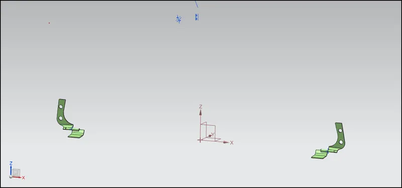
This tool is very useful with aid of this tool we can easily make a mirror copy of our assembly this tool is present in assembly workbench only. We have mirror the hinge assembly by using this feature tool.
- Thicken:
This feature is used to create a solid body from a thin face by providing a thickness value to it.
6.1 Deciding placement of Striker:
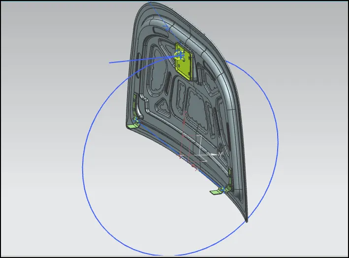
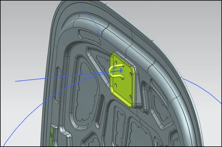
To decide the position of the striker on the hood inner panel, first we have to fixed the position of hinges on the hood inner panel. Once it is done then take construct two points one on each hinge by taking centre point of hinge. Then draw a line starting from one point to another point of hinge, this line forms our hinge axis along which our hood will rotate when we open or close the hood.
Now, by taking midpoint of this line draw a circle normal to the line take approximate diameter of the circle initially, after that draw a line which is tangent to the circle also draw a vertical line whose one end gets coincident with the end point of tangent line. This forms the trajectory path of our hood.
Furthermore, construct similar line on striker taking midpoint and constraint this line with the trajectory path as shown below.
6.2 Images of final assembly of hood
Front view
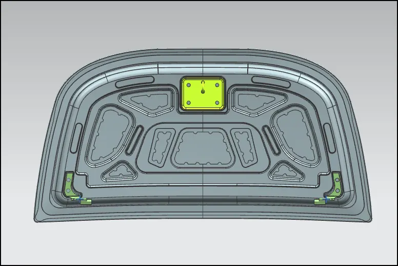
Top View
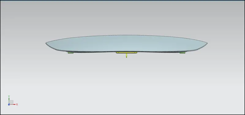
Side View
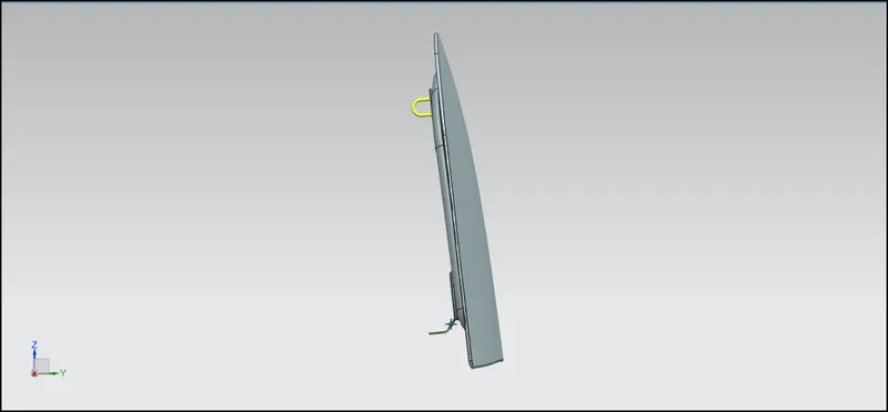
Isometric view
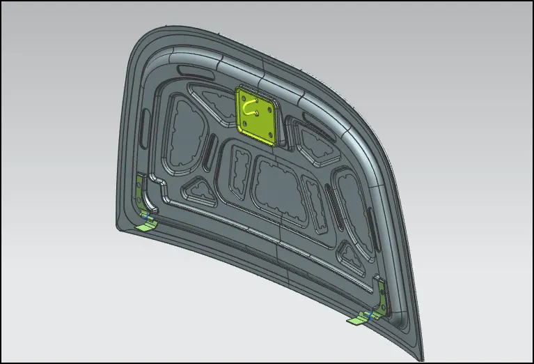
Cross section view
Conclusion: Hence, we have successfully completed our hood assembly by modeling all the components of hood that is hood outer panel & inner panel, striker and hinge assembly by following all the standard dimensions as given in input data of hood also learnt about heming process and manufacturing process of hood component i.e deep drawing, etc.