Hood design-Week 2
1. Project Name: Hood design
2. Aim: To design a complete front hood and its components as per the customers requirements.
The input data:
Outer skin data and Hood Thickness Information
- Outer Panel Thickness = 0.75mm
- Inner Panel Thickness = 0.75mm
- Reinforcement Thickness = 1.5mm
Master section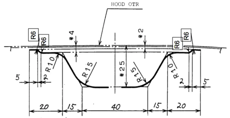
Hemming data 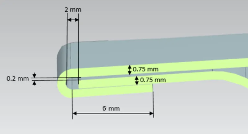
Mastic data 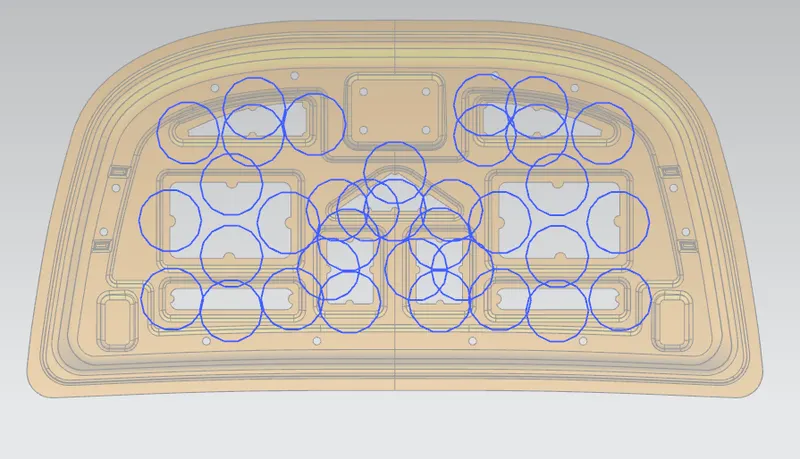
Hemming Front Relief: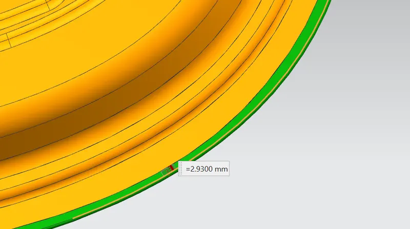
Rear relief: 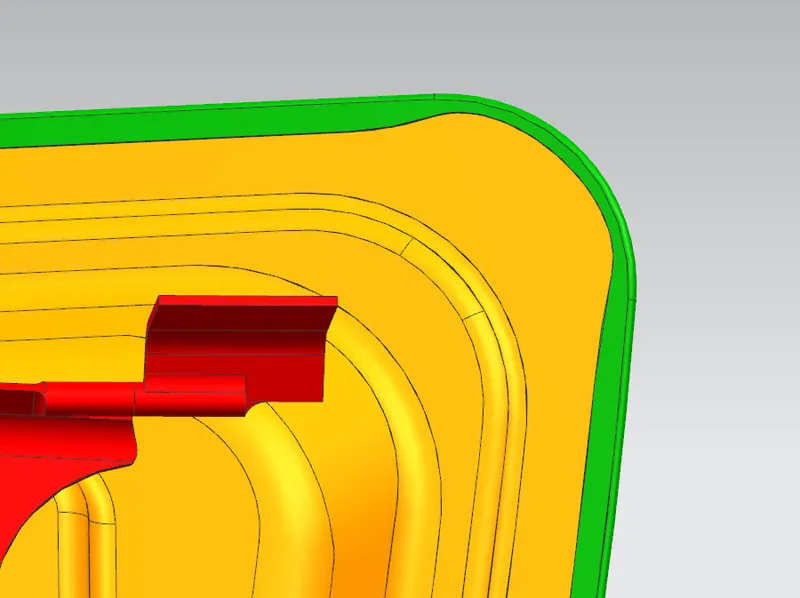
Hood and its components.
List of components:
1. Hood outer panel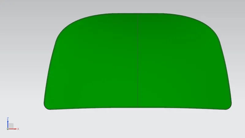
2. Hood Inner panel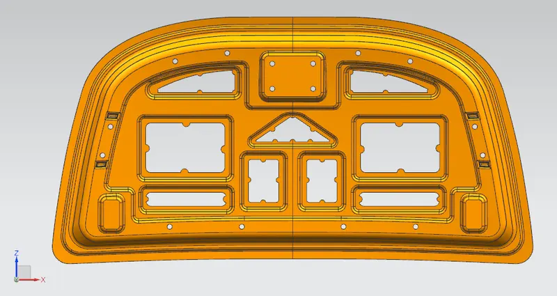
3. Hinges
4. Striker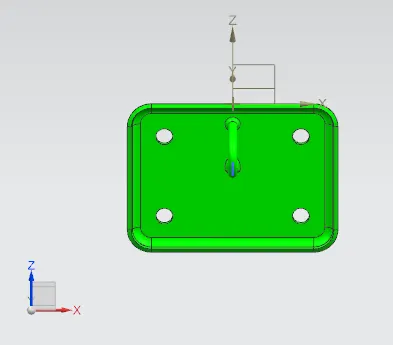
5. Reinforcement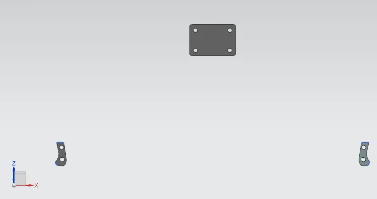
6. Mastic data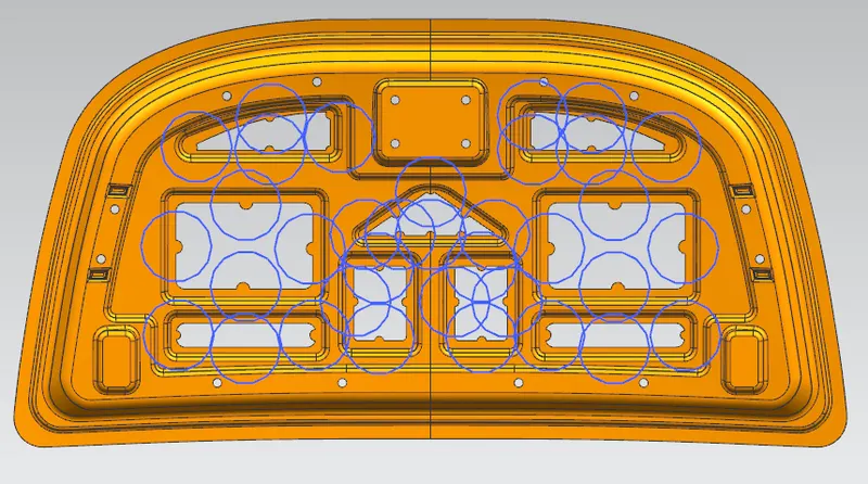
3. Description:
Designing of components:
A. Hood outer
1. Starting with Hood outer panel, the surface offests are created to obtain the working surface.
2. Trim the body to half using the cordinate planes ZY
3. Create surface offset and Trim extensions to create three surfaces at the heming region.
4. Using face blend option to create hemming the outer surface.
5. Use curves on the surface and trim sheet option to create reliefs at front and rear locations.
6. Add thickness of 0.75mm to the surface usign thicken option to the surface.
B. Hood Inner
1. Similar to outer pannel create a working surface and organise the tree into features groups.
2. First surface offset and following the master sections to create the required offsets.
3. First surface offset at 2mm, second surface at 4mm and the last surface at 25mm from the working surface.
4. Based on the Wrap Around Distance and Pedestrain safety requirements the embosses are created on the inner pannel of 5mm depth.
5. These embosses create lesser impact zones for the pedestrains in case of impact.
6. The embosses are created with a draft angle of 10 Degrees for the Deep Drawing of sheet metal stamping while manufacturing process.
7. The beading embosses are created in order to crumble the hood surface by pushing the outer pannel upwards in the +ve Z direction rather than intending into the cockpit.
8. Cosnidering the NVH the embosses for the Hinge are created with the embossed face straigth surfaces parallel to the outer surface skin for assembly of hinges.
9. Add thickness of 0.75mm by using thicken option.
C. Hinges Reinforcement
1. In assembly module using wave geometry linker extract the surface from the given Hinge assembly to create the reinfrocement.
2. Add thickness of 1.5mm to the material using thicken option.
D. Striker Reinforcement
E. Mastic data
1. The Mastic are the absorbing and supporting material between the Outer pannel and the Inner pannel.
2. The are semi solid material applied between the outer and inner pannels and after corrosion treatment the materials gets hardened creating the required support and also the vibration absorptions.
3. The applciation is basically are in circular sections around 80mm diameters and the location of the application are provided on the inner pannels.
Assembly of the components:
1. Add Outer pannel to the assembly module and fx the part.
2. Add Inner pannel and Use align option to align the CSYS of Inner pannel to Outer pannel at all the three planes.
3. Allign the hinges to the Hinges embosse created constraining in Z-axis and translating motion X-axis.
4. Using the hinges center axis parallel to X axis and mid point of the axis to create a circle in ZY-plane to locate the Striker location.
5. The Striker position is in tangency to the circle drawn through the hinge axis.
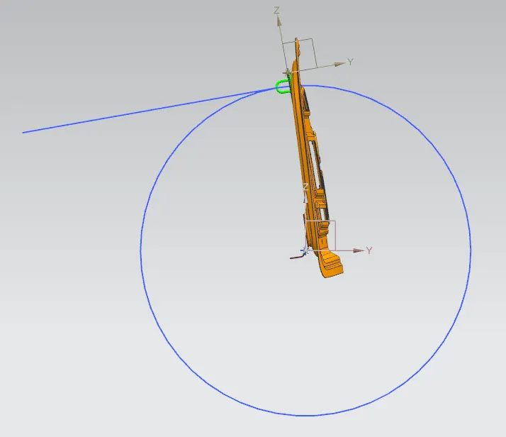
6. Now fixing the striker location using the prefer touch for the rear face of the striker to the striker embose on the inner pannel.
7. Similarly fix the Hinges to the Hinge embose using the prefer touch for the surfaces and align option for the planes and coordinate system.
8. Hinge and striker reinforcemens are placed on the behind of the inner pannel to support the hinges and striker (convert the point loads to locally distributed loads)
4. Conclusion:
The Hood design is executed along with the Input requirements for the Wrap Around Distance, Pedestrian safety, Hemming relief and Deep Drawing of Sheet metal stamping. The each components are design as per required input parameters.