Hood design-Week 2
Project Report - HOOD DESIGN
A car bonnet, or hood, is the hinged cover that rests over the engine compartment of a car. It is designed to provide access to the engine for maintenance and repairs.
While "car bonnet" and "car hood" are often used interchangeably, they refer to the same component. Located at the front of the car, the car bonnet acts as a protective cover for the engine and other vital elements.
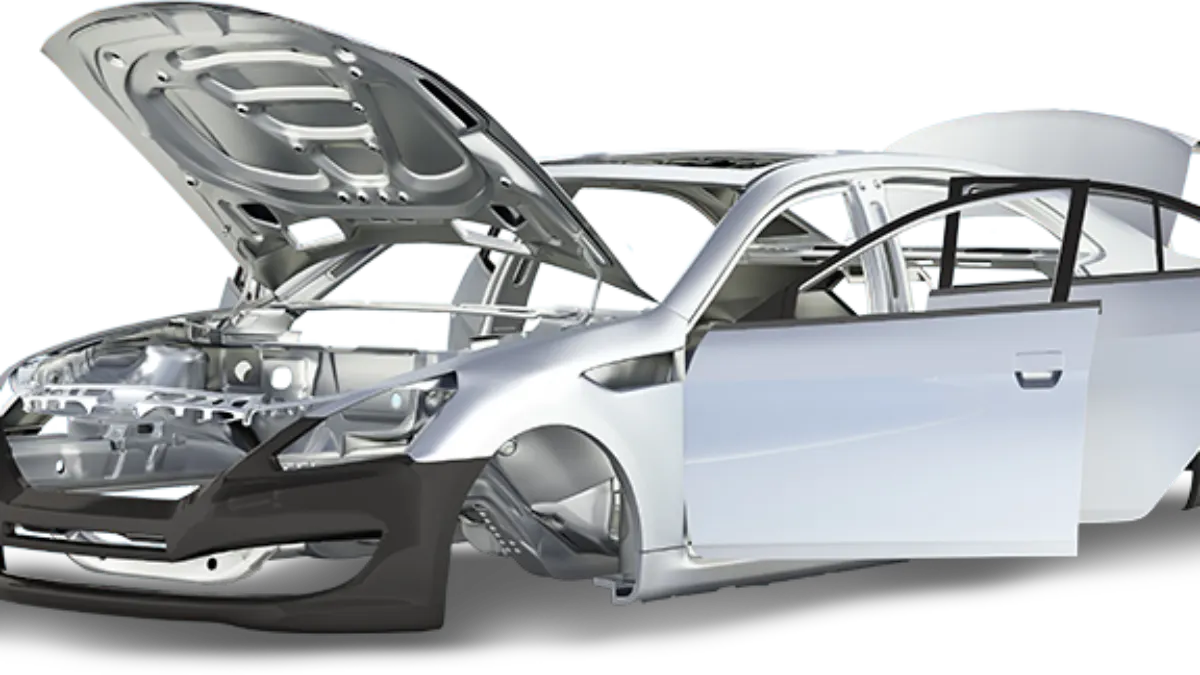
The following main parts considered in Hood assembly.
i. Hood Outer. ii. Hood Inner. iii. Hood Latch System. iv. Hood Hinge System.
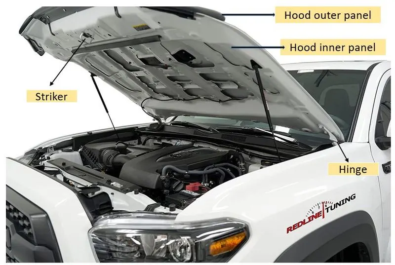
1.Hood Outer Panel
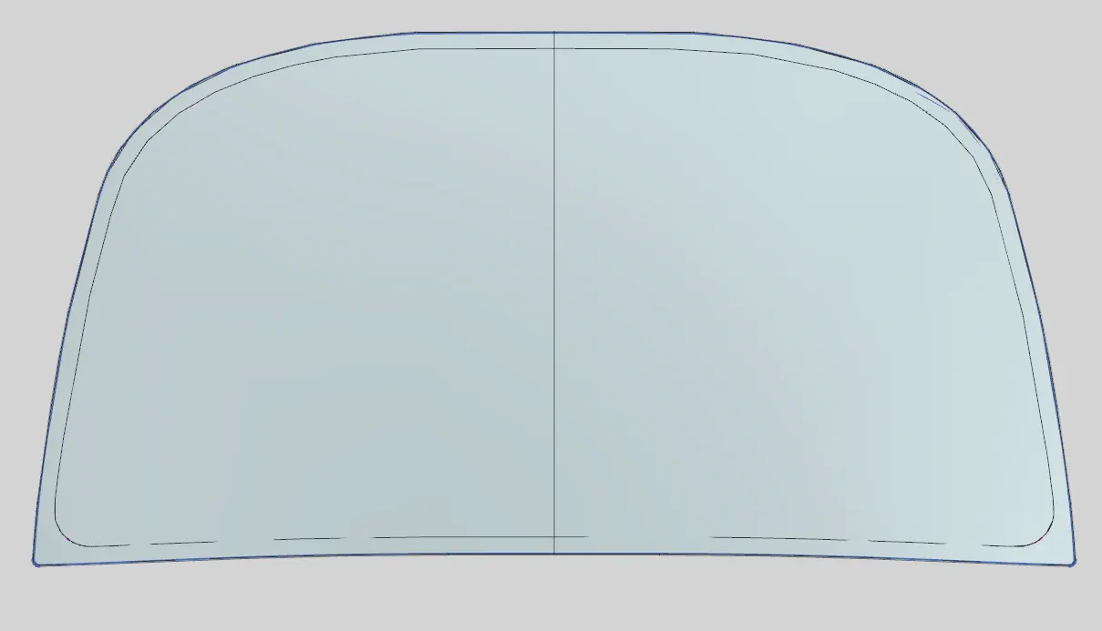
The Outer Panel has the aesthetic Look to hood assembly but on its own it is very weak and not capable of handling force during Impact. The outer panel is designed with an aerodynamic shape to minimize resistance.
2.Hood Inner Panel
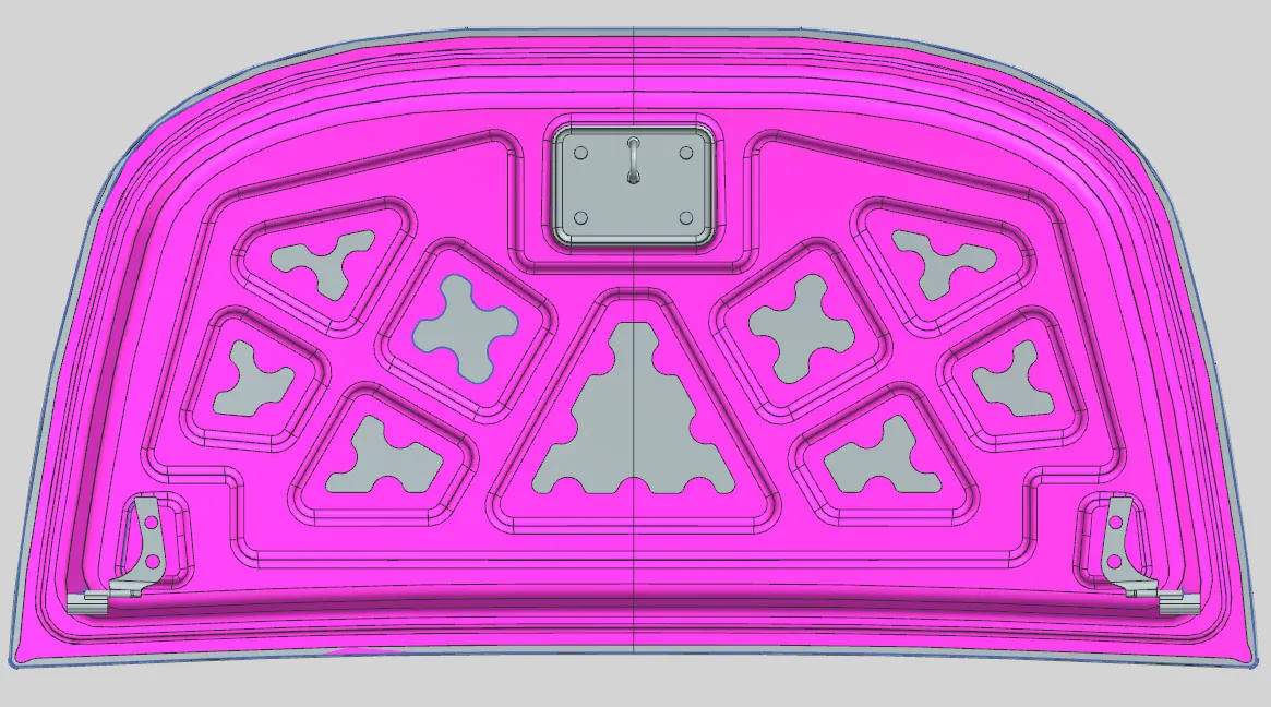
the inner pannel of the Hood is not visible to customer but this is the engineering feature of the outer panel. it act a a reinforcment to hood outer pane, its providing structure support and strength to outer panel. the hood outer and inner panel
3.Hinge
hinges are essential components that allow the hood to pivot open and closed smoothely. hood hinges are typically made of sturdy materials like aluminum or steel to withstand the weight and stress of hood.
4. Striker
The striker plays a crucial role in insuring that the hood remains securely closed while the vehicle is in motion, thereby preventing it from unexpectedly opening and potentially causing accidents or damage. it provides a reliable point of connection for the hood latch mechanism, maintaining the integrity of the hood latch sycstem.
Design Consideration In Hood Design:
Pedstrian Safety Rating, Crash Regulations, NVH, Opening Angle, Hinge Reinforcement, latch and striker reinforcement, mastic seals and stiffner pad, hood Stray these are points to consider while design hood.
1.Pedestrian Safety:
Design features such as hood deformation zones and energy absorbing materials help reduce the severity of injuries in pedestrian collisions
2.Crash Regulations
the hood should be designed to crumple and absorb impact energy in frontal collisions, protecting occupants and minimizing damper to the vehicle's structure. the embosses also provided to hood inner panel in such direction that the force generated due to collision go along embosses towards the hinges for passenger sefety.
3. NVH
design feature to minimize noice, viabration, and harshness (NVH) levels during hood operation and while driving. NVH analysis helps identify where a sound is coming from and why .Engineers can then reduce or eliminate unwanted noices as well as inhance beneficial sounds. To reduce NVH level in hood mastic seals and stiffner pads also use in between hood outer panel and hood inner panel.
4.Opening Angle
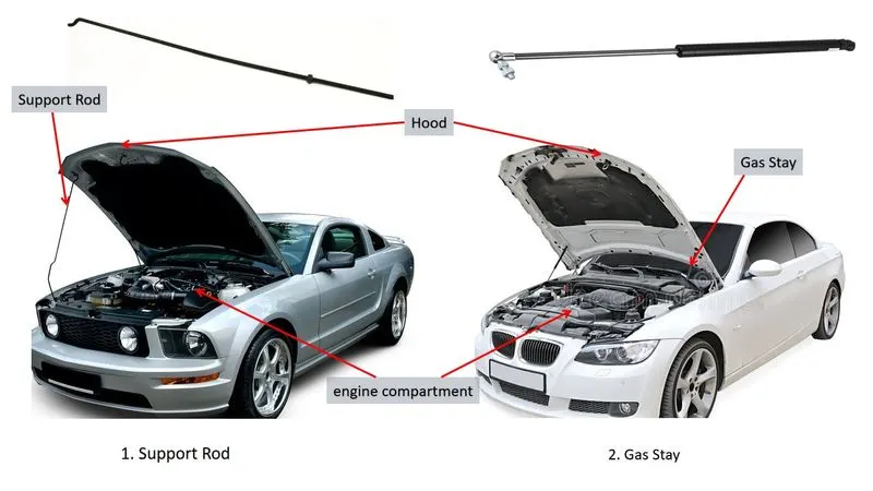
the human height should consider for deciding hood opening angle. the head of the human should not strike on the hood striker. The opening angle differs from region from region as average height are different. The hood stay is used for supporting the engine hood of motor vehicle in its open position. this hood stay Rod defines hood opening angle.
There are Two methods of hood stay 1.Support Rod 2. Gas Stay
Manufacturing Processes:
1.Blanking:
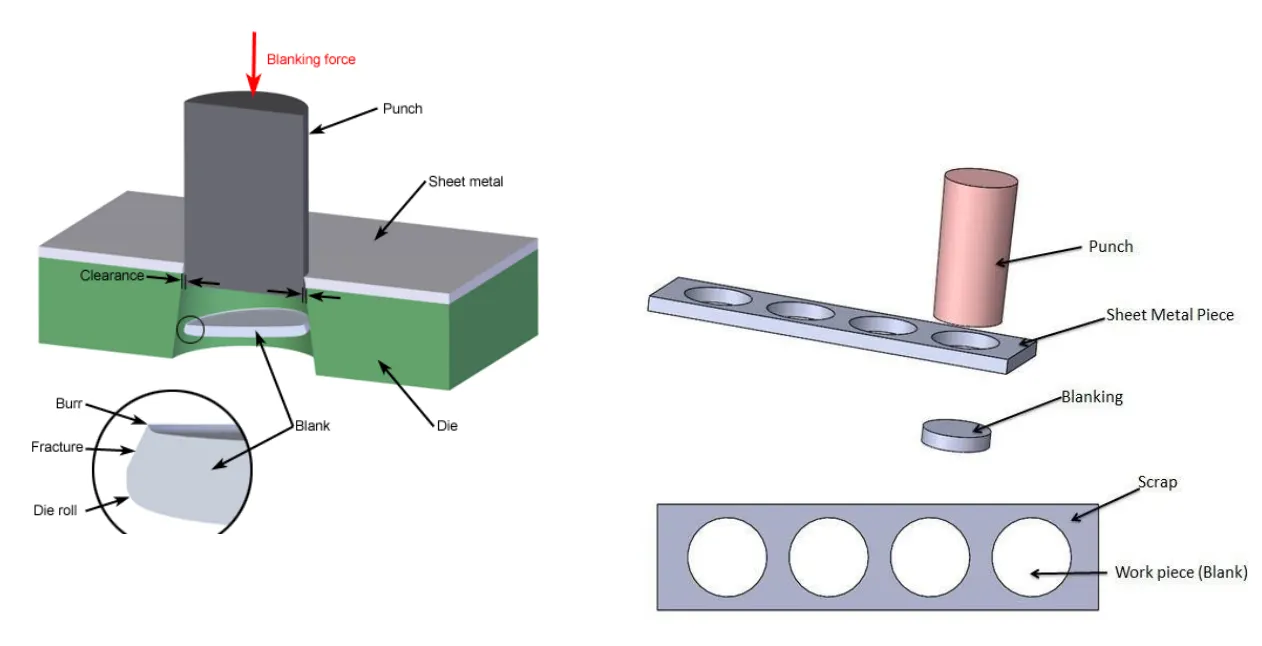
Blanking is a cutting process in which a piece of sheet metal is removed from a larger piece of stock by applying a great enough shearing force. in this process the piece removed, called the blank, is not scrap but rather the desired part.
blanking can be used to cutout parts in almost any 2D shape But most Commonly used to cut work pieces with simple geometries that will be further shaped in subsequent processes.
the blanking process requires blanking press, sheet metal stock, blanking punch and blanking die.The sheet metal stock is placed over the die in the blanking press. The die, instead of having a cavity, has a cutout in the shape of the desired part and must be custom made unless a standard shape is being formed.
2. Deep Drawing
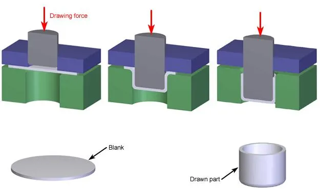
Deep drawing is a metal forming process in which sheet metal is stretched into the desired part shape. A tool pushes downward on the sheet metal, forcing it into a die cavity in the shape of the desired part. The tensile forces applied to the sheet cause it to plastically deform into a cup-shaped part.
The blank is clamped down by the blank holder over the die, which has a cavity in the external shape of the part. A tool called a punch moves downward into the blank and draws, or stretches, the material into the die cavity. The movement of the punch is usually hydraulically powered to apply enough force to the blank. Both the die and punch experience wear from the forces applied to the sheet metal. The process of drawing the part sometimes occurs in a series of operations, called draw reductions. In each step, a punch forces the part into a different die, stretching the part to a greater depth each time. After a part is completely drawn, the punch and blank holder can be raised and the part removed from the die.
3.Hemming
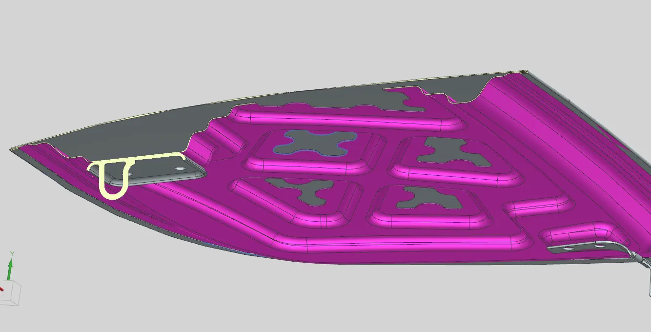
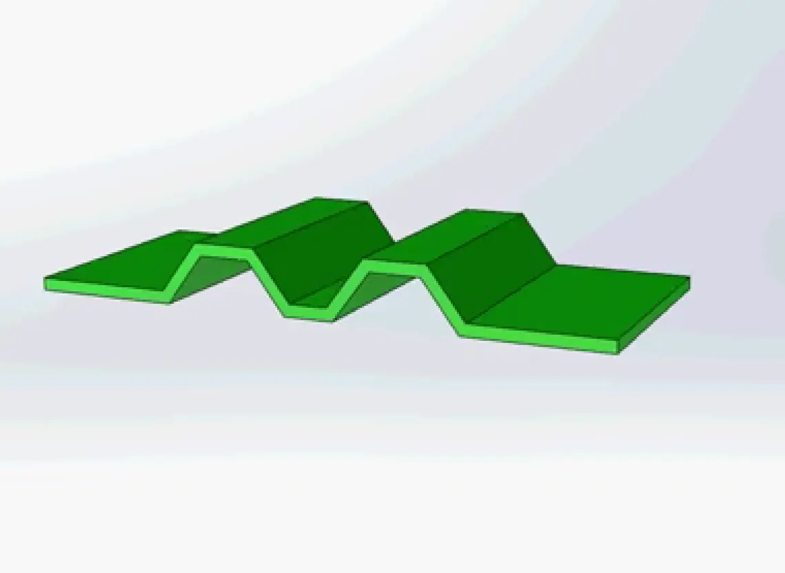
Hemming is a forming operation in which the edges of the sheet are folded or folded over another part in order to achieve a tight fit. Normally hemming operations are used to connect parts together, to improve the appearance of a part and to reinforce part edges. Hemming increase the stiffness of the part, improves its appearance, and eliminate sharp edges.
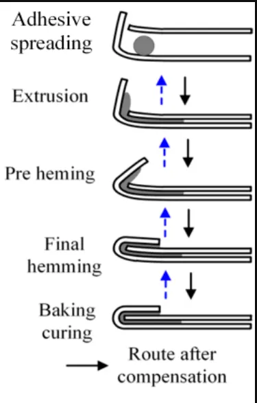
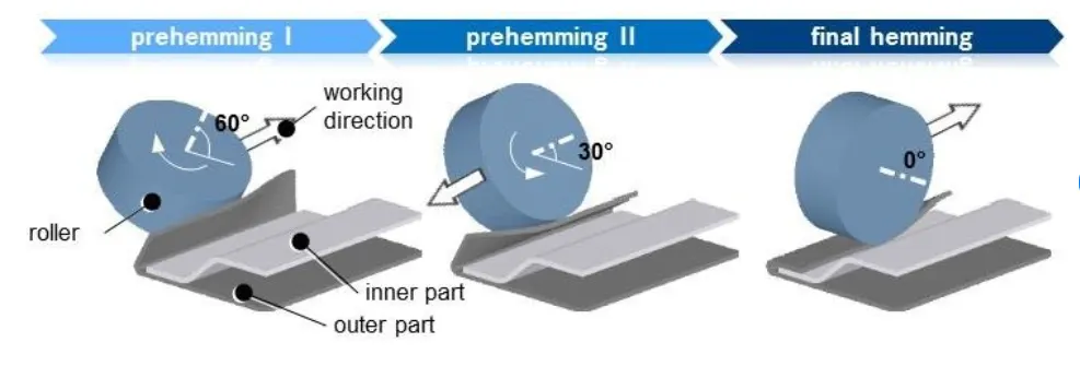
There are many techniques to hemming of sheet. hemming by rollers technique is commonly employed in automotive manufacturing for creating stiffened edges on vehicle body panels, such as doors, hoods,and trunk lids. here is how hemming rollers works shown in image.
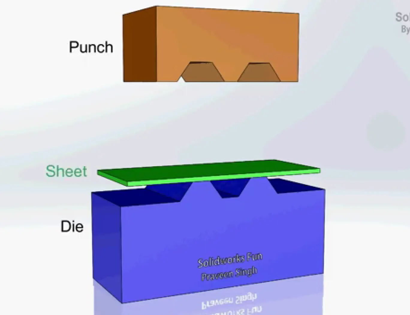
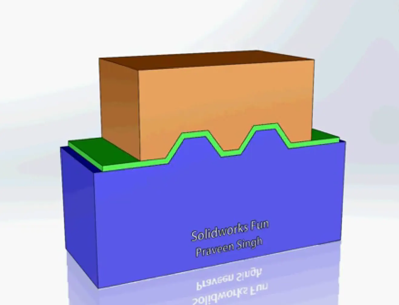
4. Embossing
embossing is a stamping process for producing raised or sunken designs or relief in sheet metal. This process can be made by means of matched male and female reoller dies, or by passing sheet or a strip of metal between rolls of desired pattern.
Hood Design Procedure:
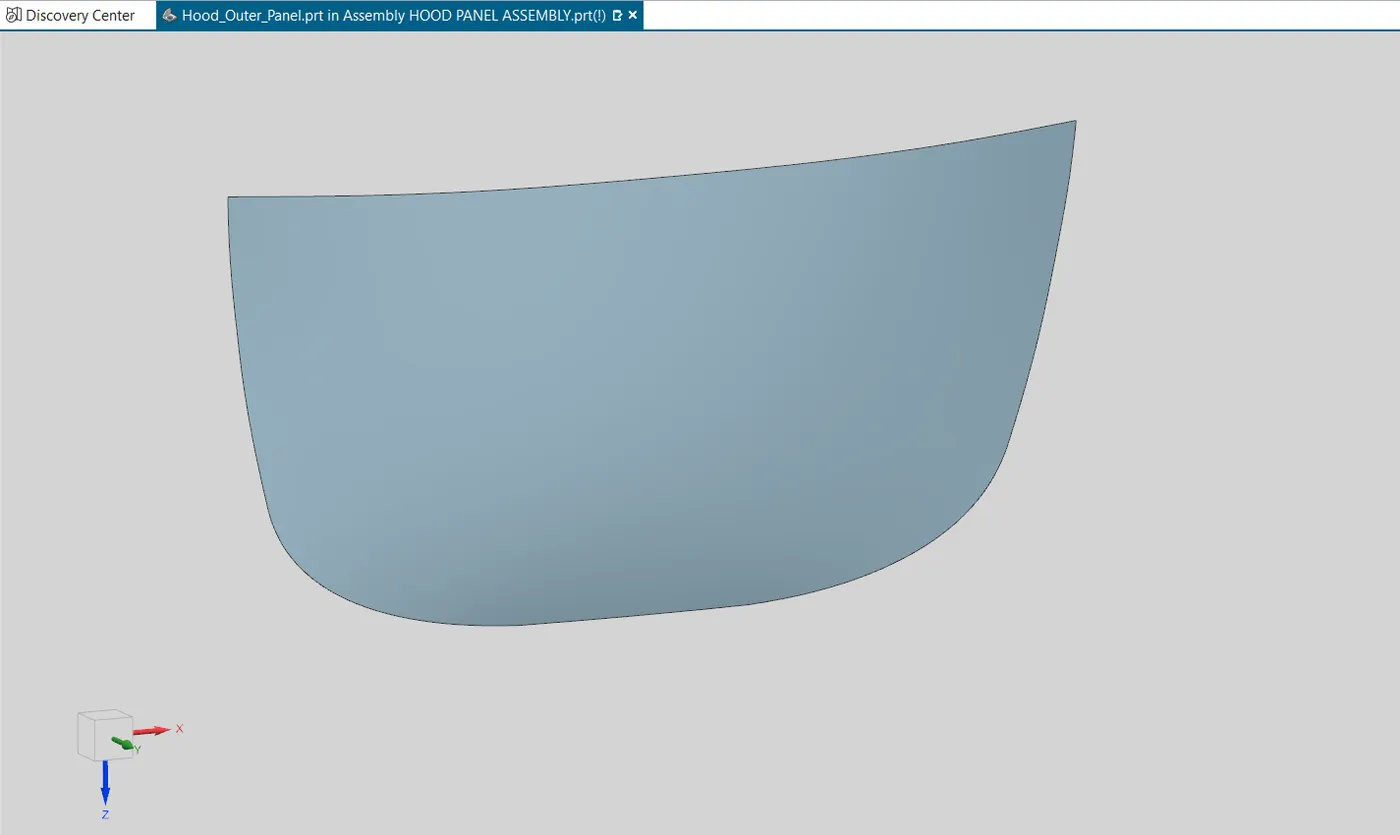
Input: here skin surface of hood outer panel and master section of hood inner pannel given as input.
Hood thickness information
1. Outer panel thickness = 0.75 mm
2. Inner panel thickness = 0.75 mm
3. Reinforcement thickness = 1.5mm
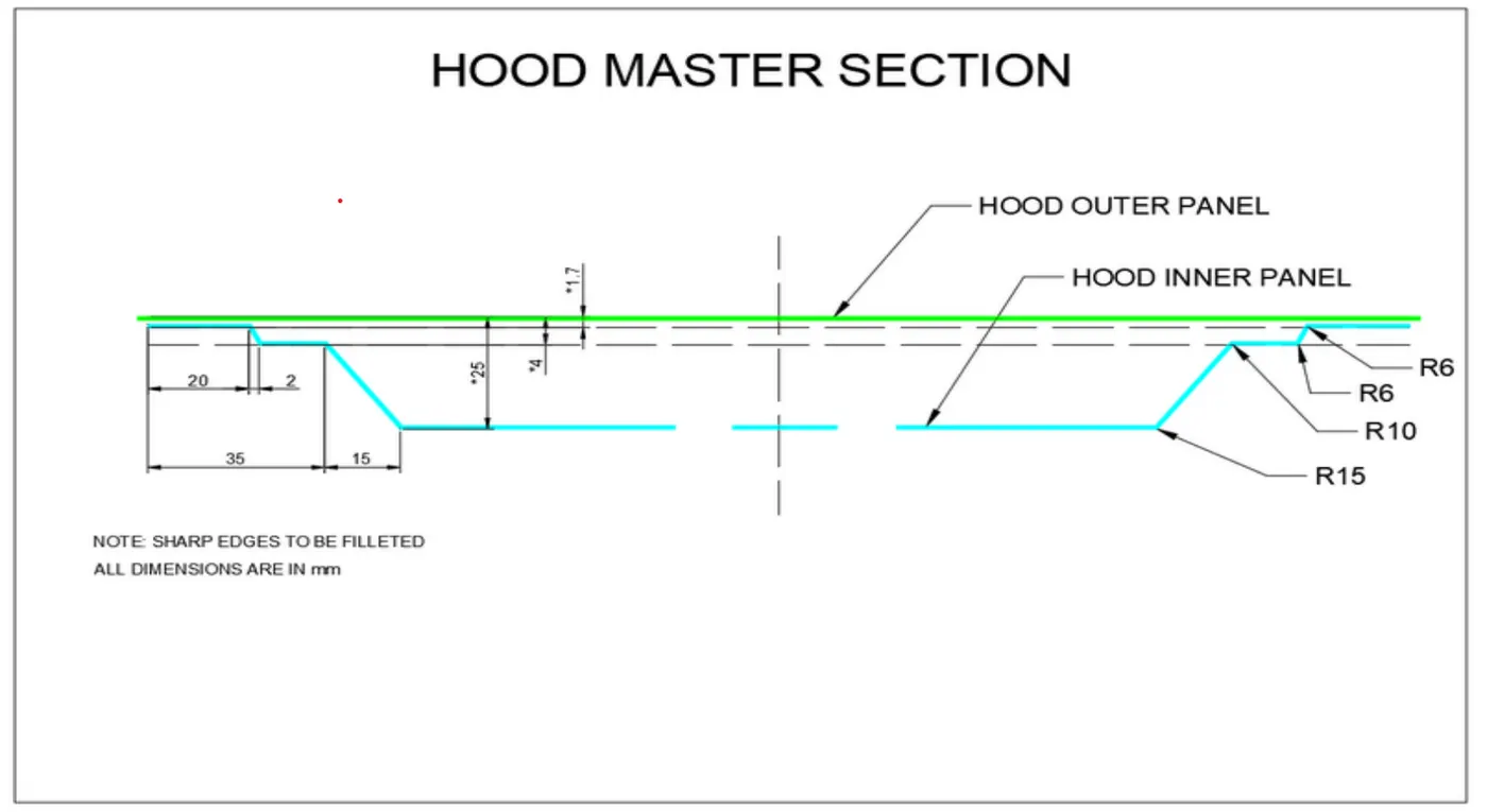
this data is used for the design of our hood inner panel, here we use the dimensions from carry out study which has been proven in last projects.
Created New assembly called Hood Outer Panel Assembly. imported Hood outer Panal part file into assembly and given Fix Constaint to hood outer panel part.
created new part hood inner panel by using New Component command.
then Activated hood inner panel part and import hood outer panel surface into hood inner panel part by using Wave Geometry Linker Command. Wave Geometry Linker is powerful command that facilitates Associativity and parametric modeling by establishing relationship between different parts or features within an assembly.
1. Tooling Direction
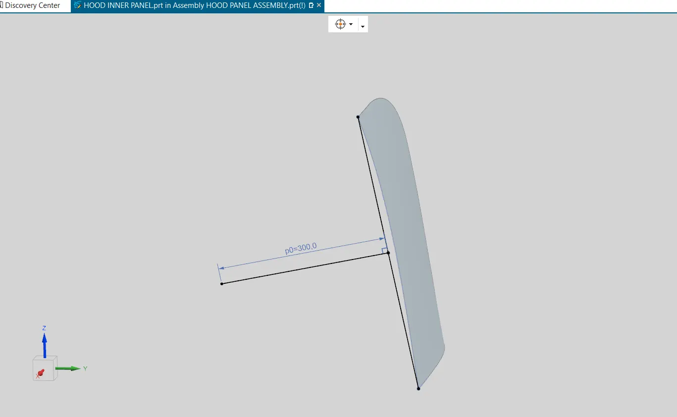
The hood inner panel is manufactured by stamping process, In stamping the direction about which tool advance toward the die called tooling direction. The faces to be stamped needs draft minimun 7° with tooling direction for manufacturing feasibility.
trimed the half to the Wave Geometry linked Surface and drawn tooling line which are perpendicular to this surface.
2. Flanges Design
To create flanges of hood inner panel i followed master section. this master section is the section of hood inner panel which has taken from carry over study. i created flanges by dimentions given in master section such as flanges depth and flanges width. Here commands used is offset, ofset in face, trim sheet, through curves, face blends.
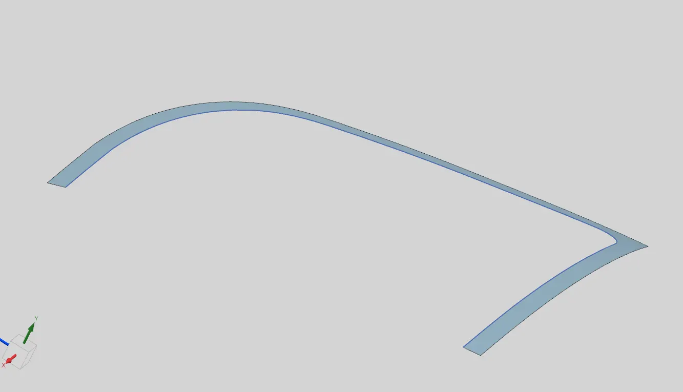
first offseted half trimed hood outer panel surface 1.7 mm, trimed half it and create edge on ofsetted surface by Offset in face command at 20 mm Offset from outer edge. and trimed first flange throuth offset surface by using Trim Sheet command.
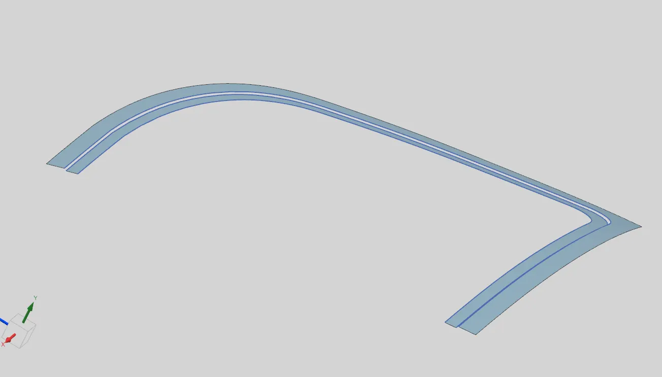
created second flange like same procedure as followed above.
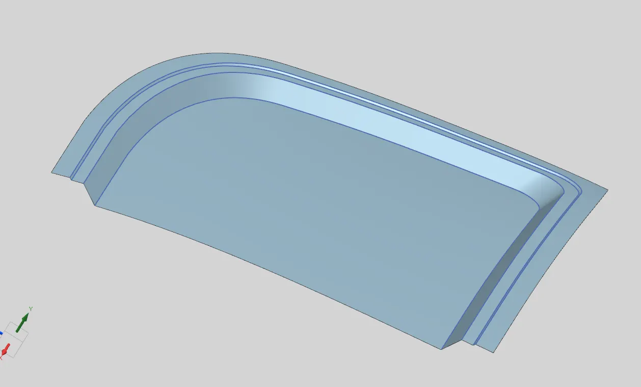
created third offset flange and joined three flanges by using through Flange Command.
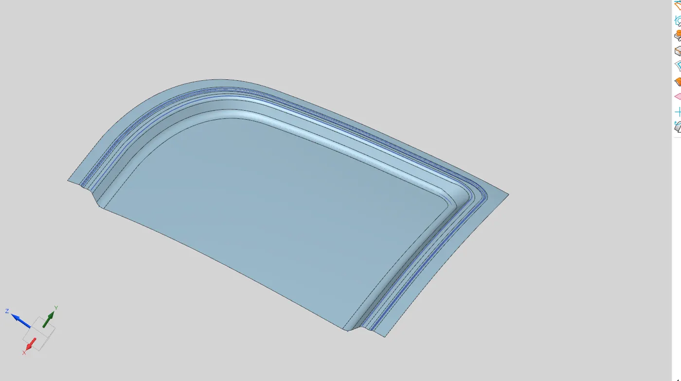
given fillets by face Blend command.
3. Embosses and Cutouts
here the hood outer panel and inner panel are seperated by mastic points or stiffner pad which having thickness about 5 mm, so emboss is provided toward hood outer panel side.this emboss we will give in two steps.
To give first emboss sketched the shape of emboss on XZ plane. keeped space and clearance for hinge mounting and striker mounting.
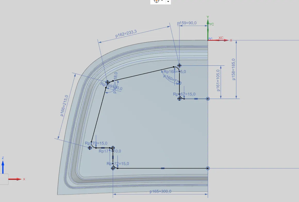
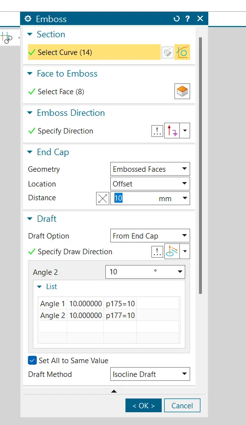
projected sketch on surface by using Project Curve Command and embossed 10mm this sketch on surface using draft 10° with tooling axis by using Emboss Command.
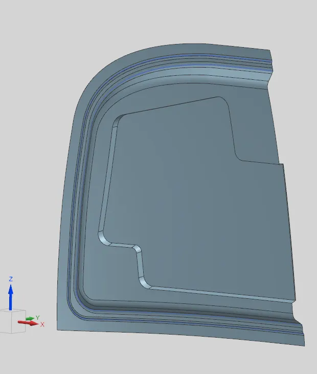
given fillets to the embossed edges of first emboss by Using Edge Blend Command.
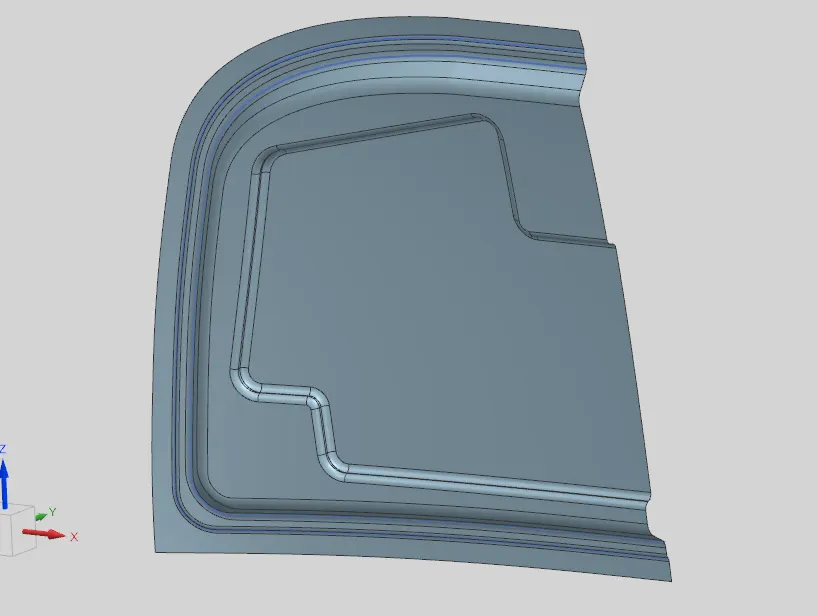
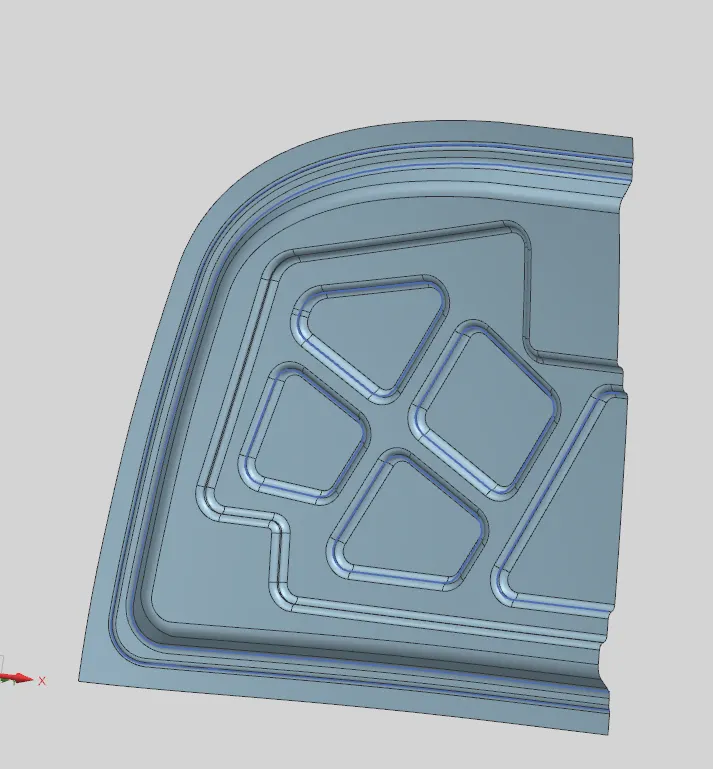
The Second emboss to be in specific manner by considering Crash Regulation. during the Crash Hood inner panel should distribute forces away from inner cabin and towards the hinges of hood for passanger safety. this enboss should act as a skelton and shold provided strength.
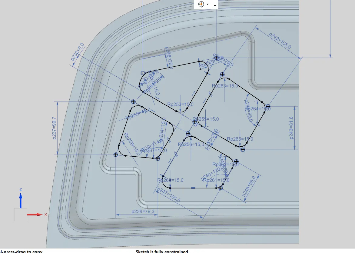
drawn the sketch which want to emboss and projected that shape on hood surface and embossed by Emboss Command. and blends given to edges.
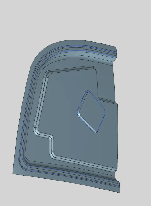
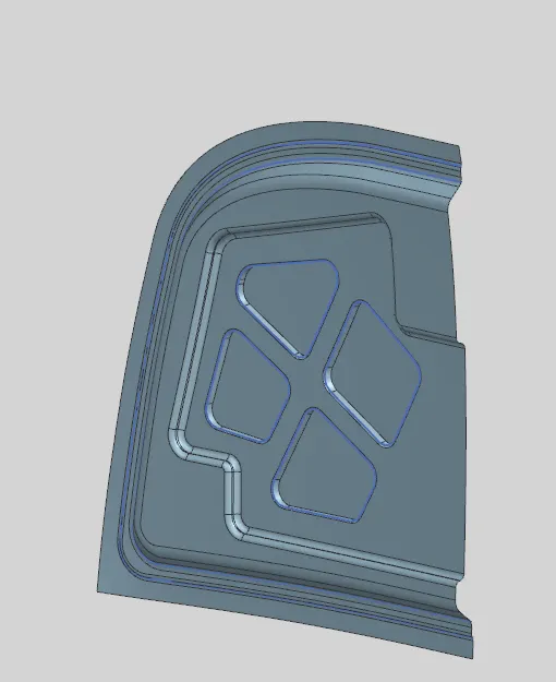
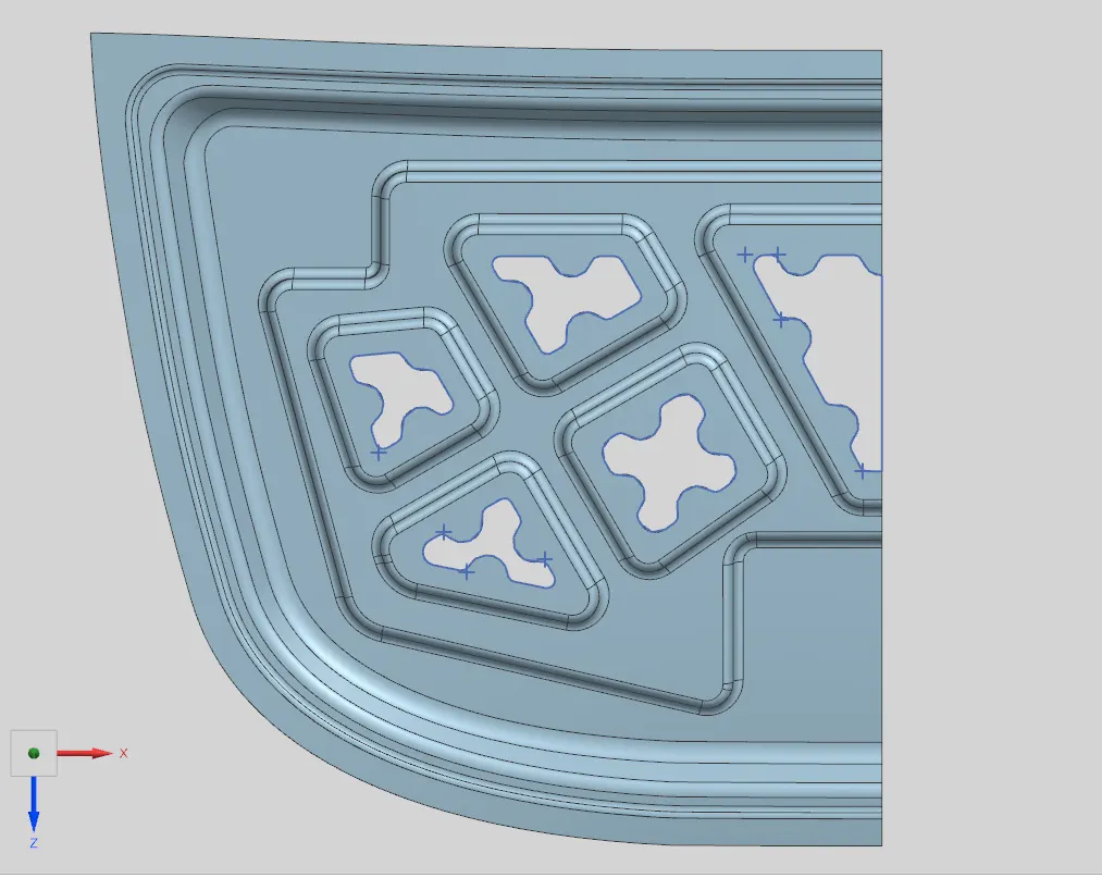
for pedestrian safety we have to give cutouts to the hood inner panel to reduce stiffness of hood. if the padestrians head get striked on hood, hood should get absord that impact by deflecting.
by using Trim sheet Command Trimed the shape and we have to keep the space for mastic points.
4. HInge Mounting
activated assembly and insert HInge assembly and Striker into Hood assembly.
for Mounting the Hinges we need Flat surface. so activated hood inner panel and created plane At angle and closer to hood inner panel. that plane we will use to create hinge reinforcement surface.
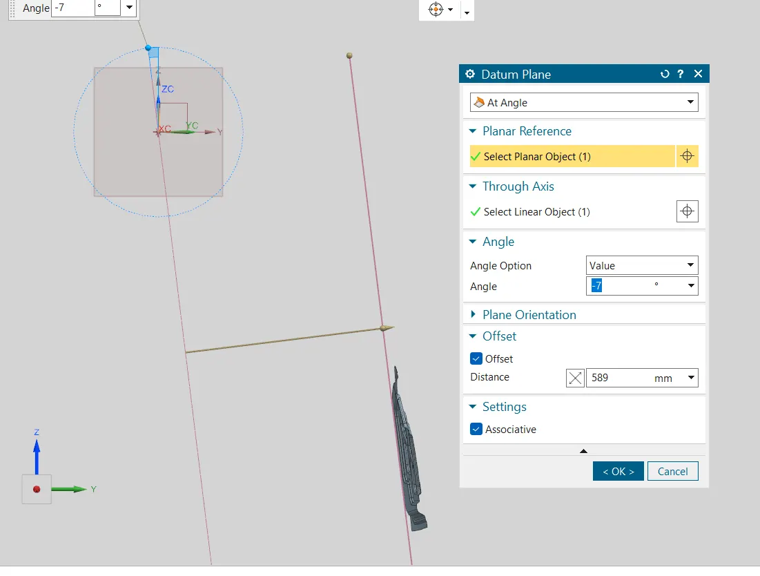
sketched the profile for hinge mounting reinforcement emboss. and embossed Hinge mounting emboss, thr embossed end cap selected a plane drawn at an angle.
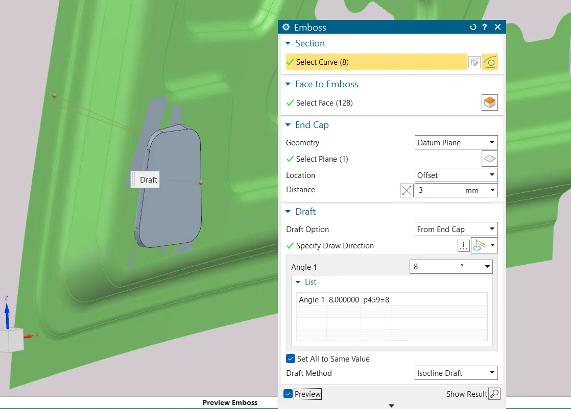
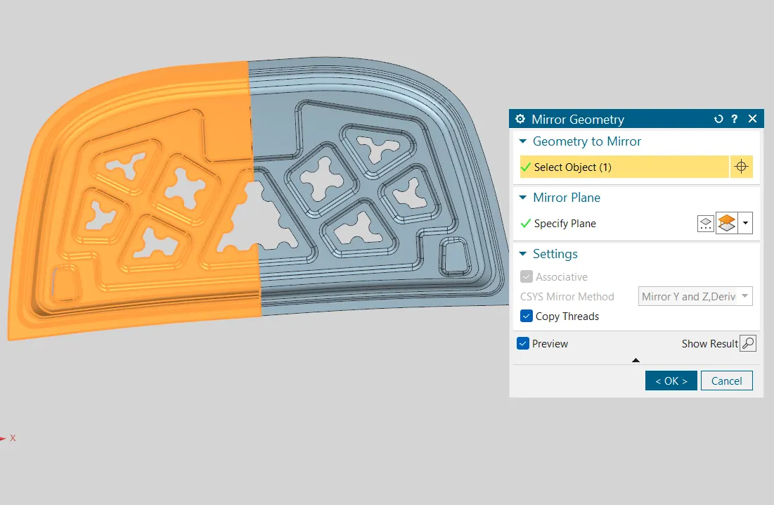
then mirrored half hood inner panel by Using Mirror Geometry Command with associative enabled. and joined mirror surface and half hood inner panel by sew Command.
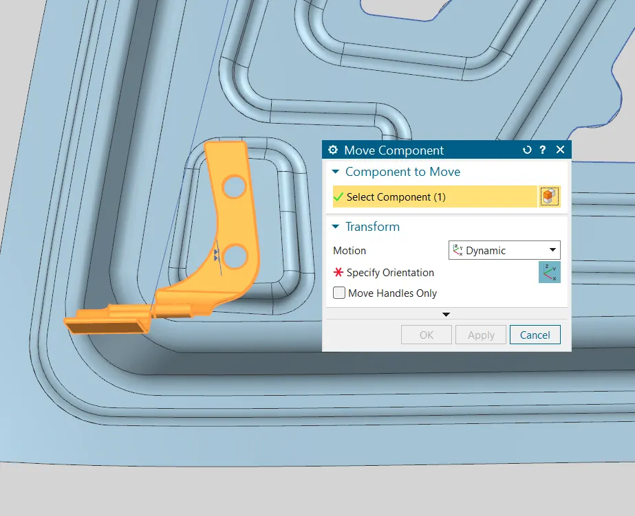
to fixing hinges at proper position, activated assembly and moved component by Move Component command as we want to mount hinge.
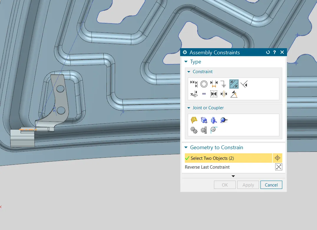
and given constraints to hinge assembly. touch constraints to hinges flats and hinge mounting reinforcement flat. parallel to hinge axis and x axis of assemby.
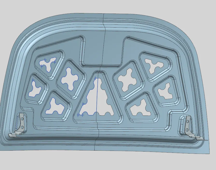
then mirror the hinge assembly by using Mirror Component Command With enabling Assoiciativity.
5. Striker Mounting
The striker mount should be always tangential to the tragectory of hood about hinge Axis. The path followed by Hood about hinge axis while opening and closing is called Trajectory. and it is in circular shape. if C Hook is properly aligned with latch then hood will properly lock, so we need striker always tangetial to hood trajectory.
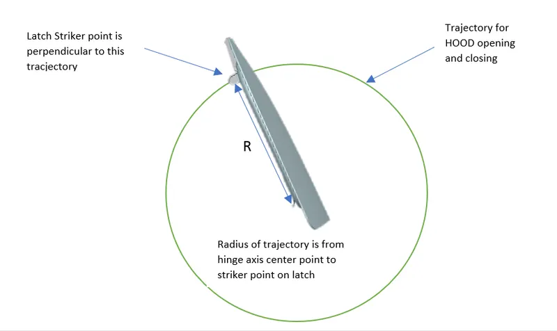
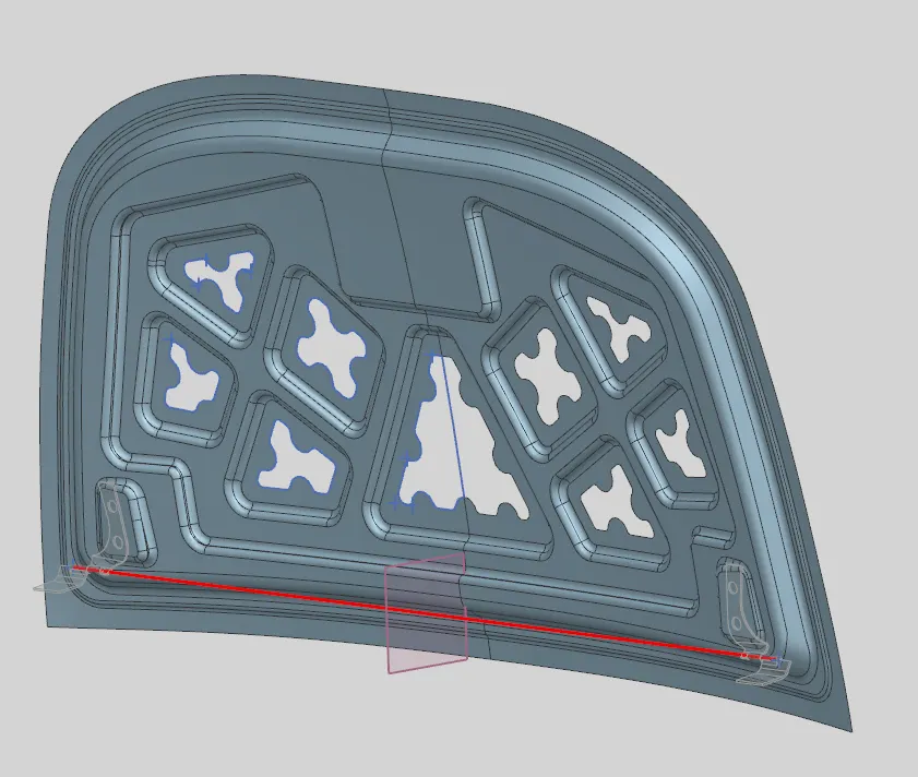
created Hinge Axis in Hood Inner Panel. To create Hinge Axis Taken Two referance Points from Hinge Part By using Wave Geometry Linker Command. and created Line throuth that two point as a Hinge Axis. created datum plane between center of hinges to draw trajectory.
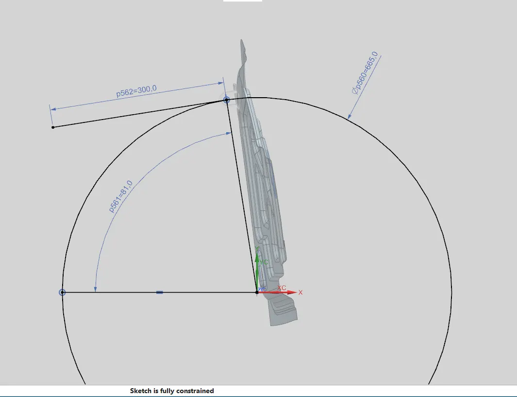
drawn trajectory circle, centerpoint taken at hinge Axis.
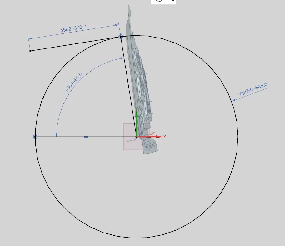
now constraint to striker with trajectory. to constraint striker lets draw the line to get align with tangent line of trajectory. Activate striker, create datum plane at center of striker and draw center axis line.
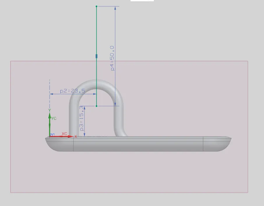
activated assembly, given align constraint of striker center plane with inner panel center plane. constraint strikers center line with trajectory tangent line and. and center point of striker with intersection point of trajetcory and tanget line.
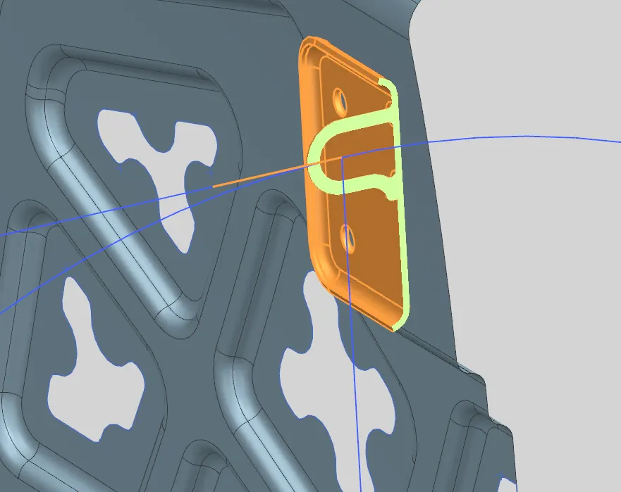
now striker fixed on its postion, we can move strker by changing the parameters in trajectory profile like angle, trajectory diameter.
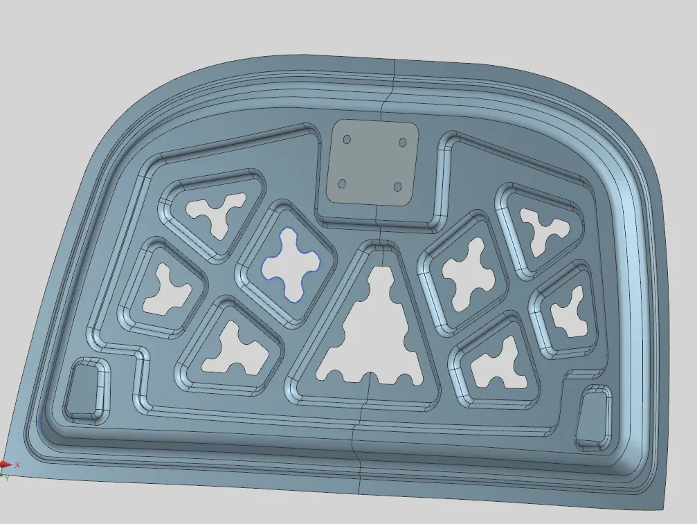
now we have to create striker mounting reinforcement to striker mounting. so lets extract rear face of Striker. By using Wave Geometry Linker Command with enabling Associativity with parent extracted the rear surface. and extended extracted sheet 8 mm using Extend Sheet Command so after giving blends to striker reinforcement there should be enought surface Contact between striker and striker reinforcement.
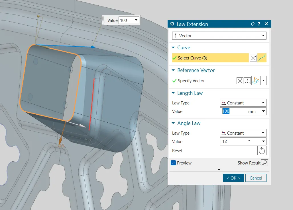
then created 100 mm Surface using Law Extention Command at 12° with tooling direction. and then joined extended mounting surface with Law Extended Surface by Using Sew Command. and then trim unwanted extra surface of joined surface by using Trim And Extend Command. and then given blends to edges.
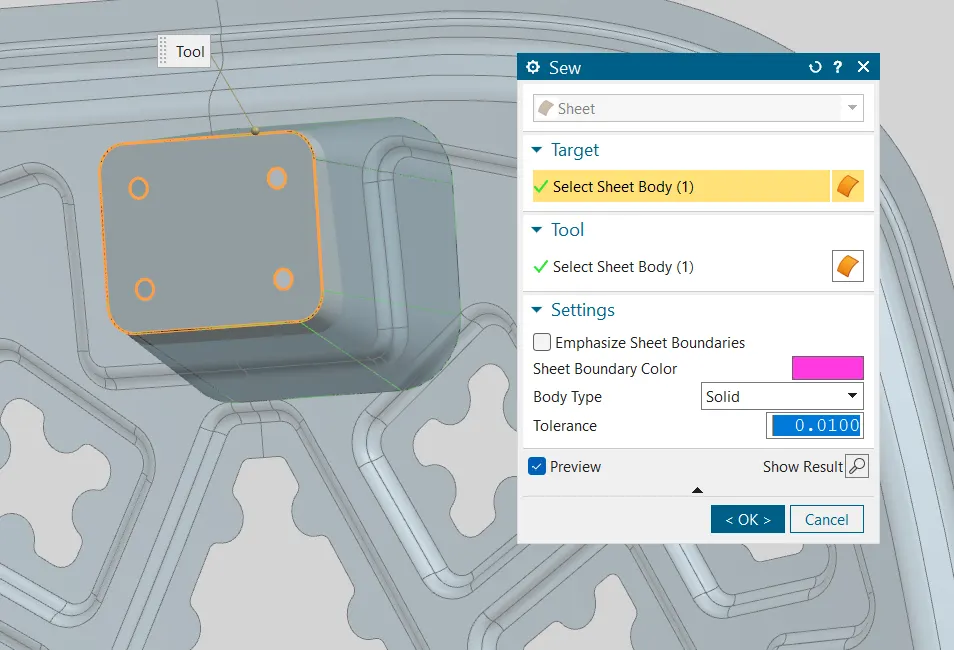
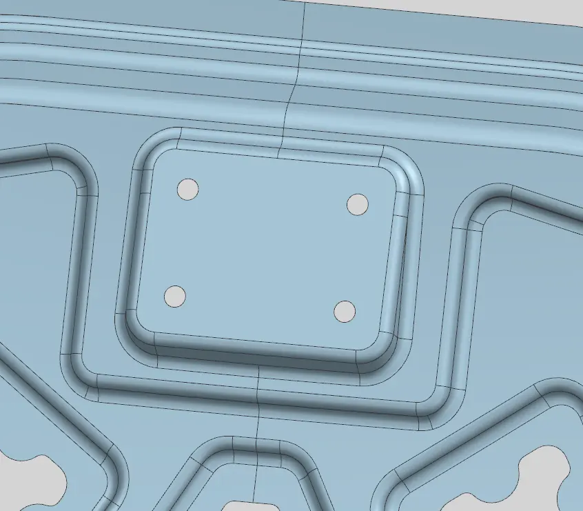
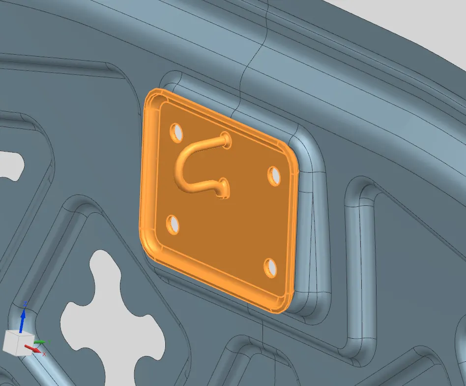
now there is a two sharp corners on sheet, let trim it. drawn curve By Bridge Curve Command at one corner. mirror this Curve by Mirror Feature Command from Associative Copy option. and trimed that corners.
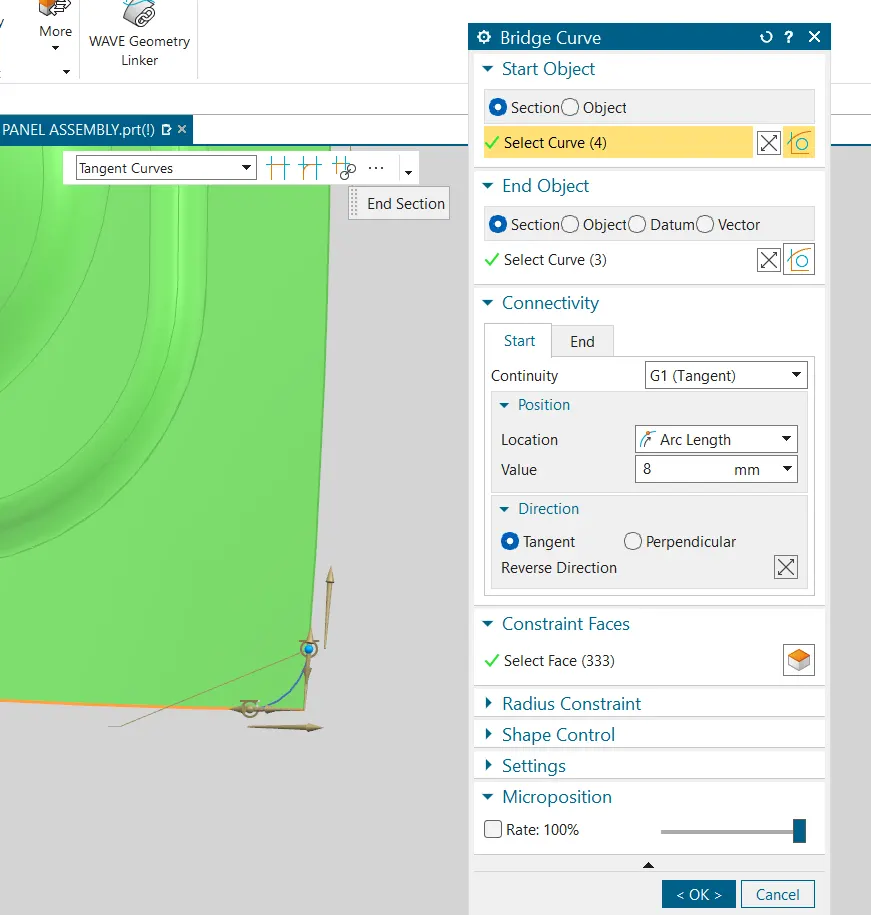
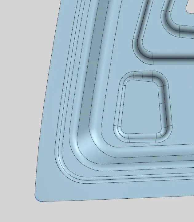
create offset in face curve and trim sheet 2 mm outer so that portion should not interfare with hemming surface.
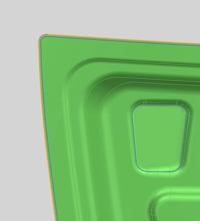
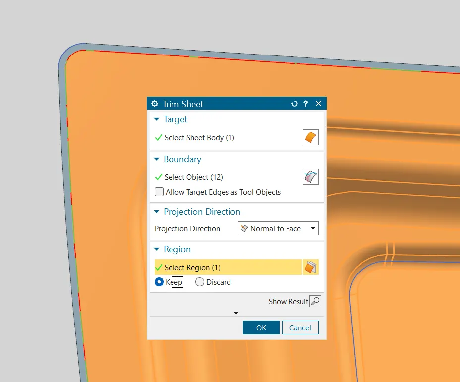
now we want to thicken the hood inner panel in direction of hood outer panel.
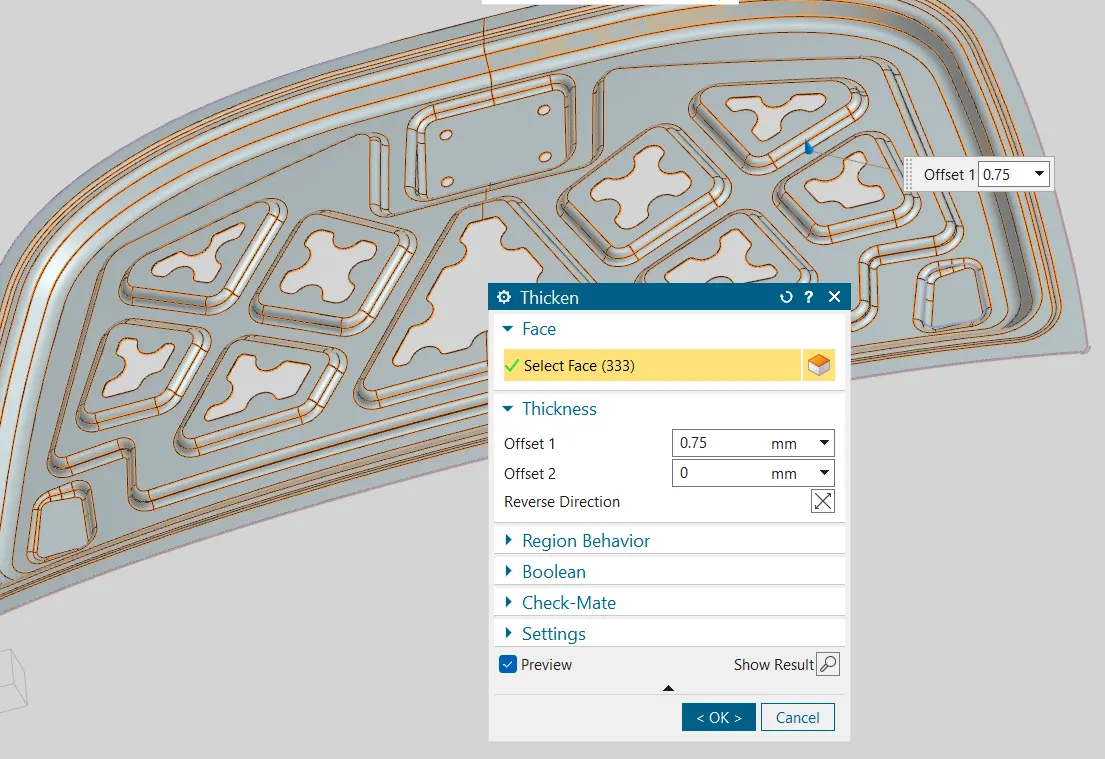
6. Hemming To Hood Outer Panel
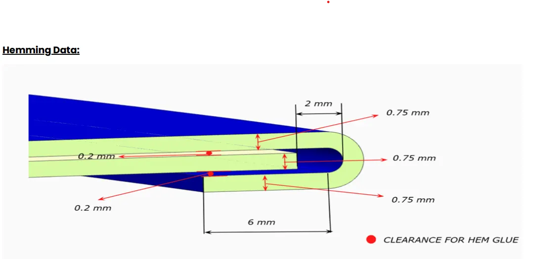
for diamension of hemming lets refer hemming data given for referance.
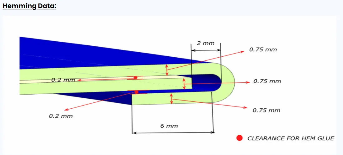
here sheet sthickness is 0.75 mm for inner and outer pannel and hemming glue appllied thickness is 0.2 mm. we will thicken the hood outer panel inside towards the hood inner panel. so create offset surface 2.65(0.75+0.75+0.75+0.2+0.2 mm)for hemming and for 6 mm width.
offset the hood Outer panel 2.65mm by using Offset Surface Command and create curve on offseted face by using Offset in face. i taken offset distance 8mm. and then trim by using Trim Sheet Command.
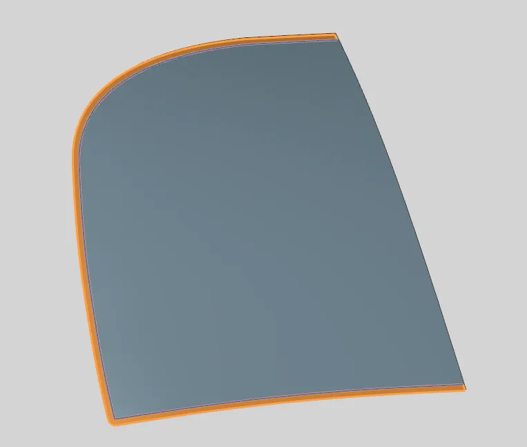
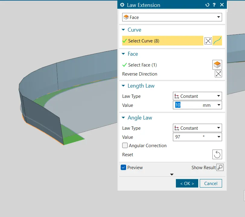
then created surface upside from trimmed offset which intersecting to the obove surface by using Law Extension Command.
then created curved surface which joining two surface by using Face Blend Command with three face.
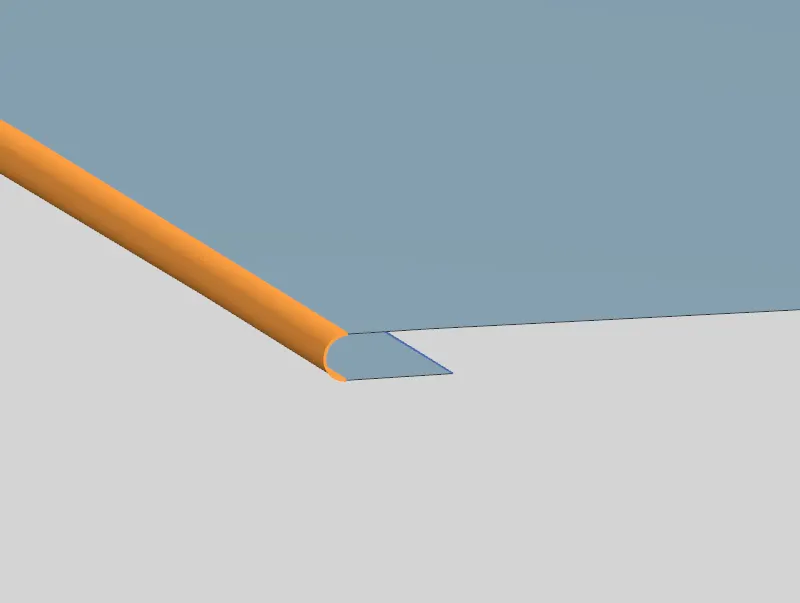
then creating hemming relief at corners. drawn curve on Surface to trim hemming felief. and trim required section.
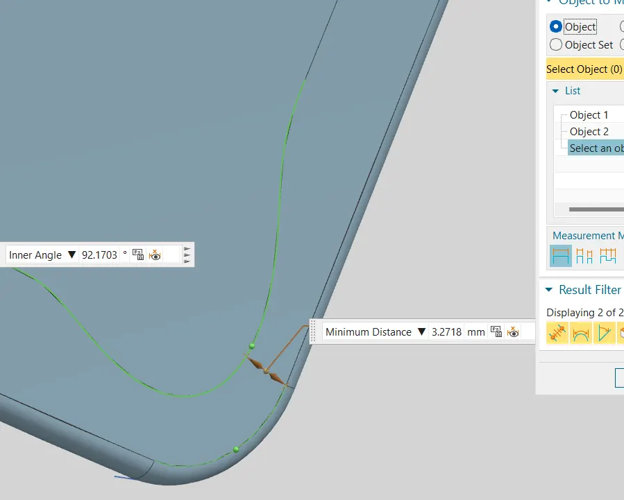
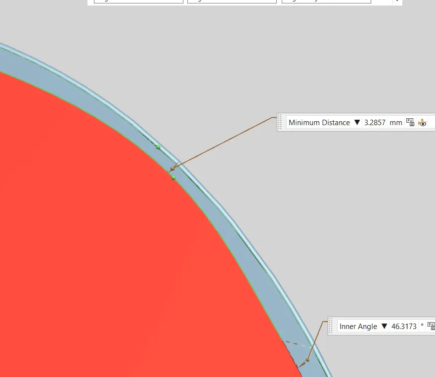
now create mirror of half outer panel with associative copy. sew the surfaces and thicken the outer panel inside.
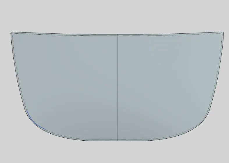
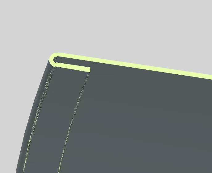
Assembly of Hood: