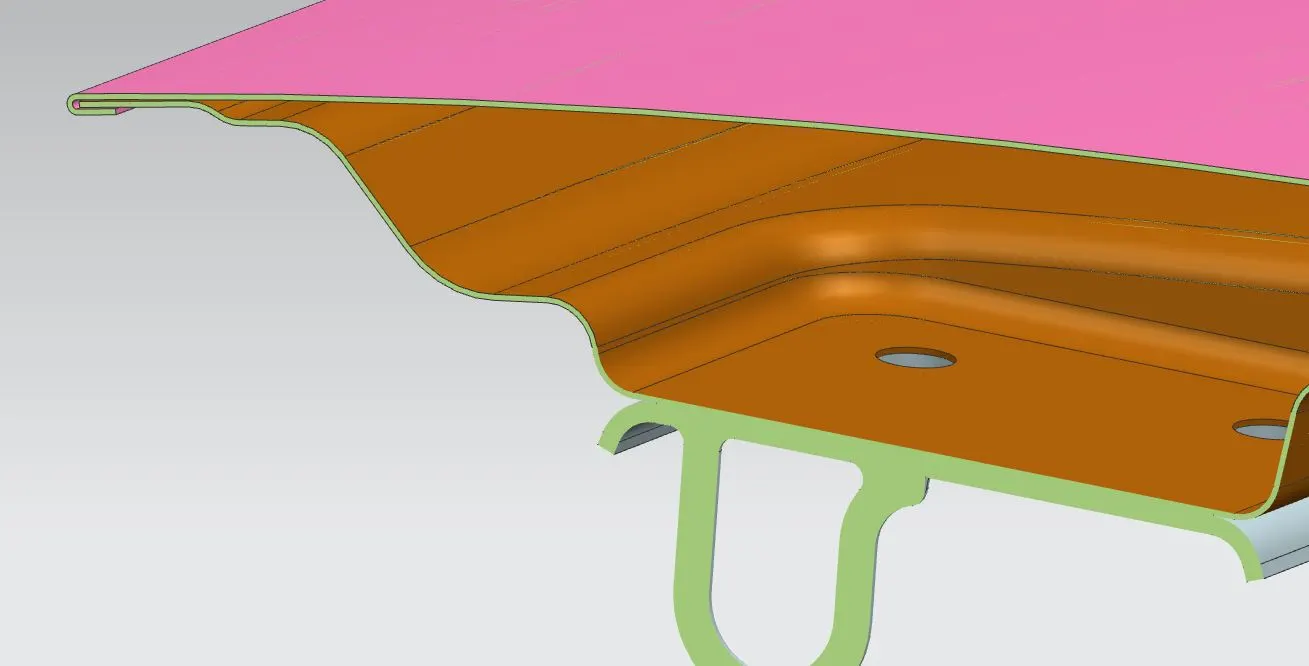
Hood design-Week 2
Objective:
The main objective of this challenge is to Design Hood outer panel, inner panel and the necessary reinforcements by following the Master section mentioned with the design parameter explained in the videos. Submit an assembly of Hood inner panel, outer panel, latch, hinge, and the reinforcements.
HOOD:
A car hood also referred to as a bonnet in some other countries is the hinged cover that rests over the engine of a front-engine vehicle. Its purpose is to provide access to the engine for repair and maintenance. A concealed latch is typically used to hold down the hood. On vehicles with an aftermarket hood and on racecars, hood pins may be used to hold down the car hood. Hoods sometimes also contain a hood scoop, wiper jets, power bulge, and/or hood ornament. Car hoods are typically constructed from steel and sometimes from aluminum. Aftermarket car hoods may be constructed from various other materials, including carbon fiber, fiberglass, or dry carbon. The hood design may vary from one make and model to another, including SUV, truck, minivan,, and passenger-car models.
Concerns regarding the severity of a potential pedestrian head injury during a collision with a motor vehicle have led to advanced hood designs on many models. Such designs may include a multi-cone inner hood panel design. An active structure that is capable of pushing the surface of the hood away from the vehicle's hard motor components in the event of a pedestrian crash is also in use. Pyrotechnic or spring force designs are often used in the the the active-hood design.
HOOD DESIGN CONSIDERATION:
The hood of a car is considered the frontal BIW enclosure component. Bonnets are designed to reduce air resistance as the air flows around the car. Apart from this, bonnets are also designed to meet several other requirements. They serve a great deal of purpose in protecting the passengers inside the car & the pedestrians in the event of an accident. It also acts as the cover for the engine.
The European New Car Assessment Programme (Euro NCAP) is a European car safety performance assessment program that has developed test specifications & rating systems for assessing pedestrian injuries during impacts with the front of vehicles such tests include a series of tests using impacts designed to bio-mimic a collision at speed of 40 km/h.
- They describe a situation in which a pedestrian is situated laterally & a car first hits one of his legs. Tests are conducted on the leg, upper leg & most importantly the head, as head trauma is most commonly responsible for casualties.
- So to avoid severe injuries to the head, the high impact area for adults & children is subjected to less thickness. Also, no reinforcement should be provided in that area as during head collision, the hood will absorb the head impact energy leading to the collapse of the hood & thus protecting the severe head injury.
- Another important criterion for the hood design is the protection of the occupants inside the car during a front collision. The design of the hood should be in such a way that during the collision, the force should travel in the upward direction through the embosses & directed towards the body of the car. Thus protecting the occupants inside.
Heming:
Hemming is a forming operation in which the edges of the sheet are folded or folded over another part to achieve a tight fit. Normally hemming operations are used to connect parts, improve the appearance of a part, and reinforce part edges.
In car part production, hemming is used in assembly as a secondary operation after deep drawing, trimming, and flanging operations to join two sheet metal parts (outer and inner) together. Typical parts for this type of assembly are hoods, doors, trunk lids, and fenders.
The accuracy of the hemming operation is very important since it affects the appearance of the surface and surface quality. Material deformations, which occur during the hemming process, can lead to dimensional variations and other defects in parts. Typical hemming defects are splits or wrinkles in the flange, material overlaps in the corner areas,,, or material roll-in. This is why it is important to use simulation tools to, on the one hand, better understand the hemming process and, on the other hand, significantly reduce the number of “trial and error” loops during tryout and production.
PROCEDURES OF DESIGN HOOD:
Hood is one of the major components of the Vehicle body. It mainly covers 2 major power transmitting components i.e. Engine and Radiator assembly. Along with covering them through its inner panel, the hood outer panel also serves a major role in the aesthetics and ergonomics of the vehicle.
It has 3 supportive components Viz.
- A) Hinges- for easy opening and closing of the hood
- B) Latch- to keep hood in correct closed position &
- C) SupportRod- helps in keeping the hood in the open position.
We will be mainly discussing
- Hood outer panel
- Hood inner panel
- Hinge Assembly
- Latch assembly
Hood inner panel is designed as per the given Master Section sketch concerning the Hood outer skin provided.
Given Input from the above link:
Hood Thickness Information
- Outer Panel Thickness = 0.75mm
- Inner Panel Thickness = 0.75mm
- Reinforcement Thickness = 1.5mm
Master Section:
Hood Outer Panel:
By using the hood outer panel we can offset the surfaces and make the inner hood panel in the assembly as a new part.
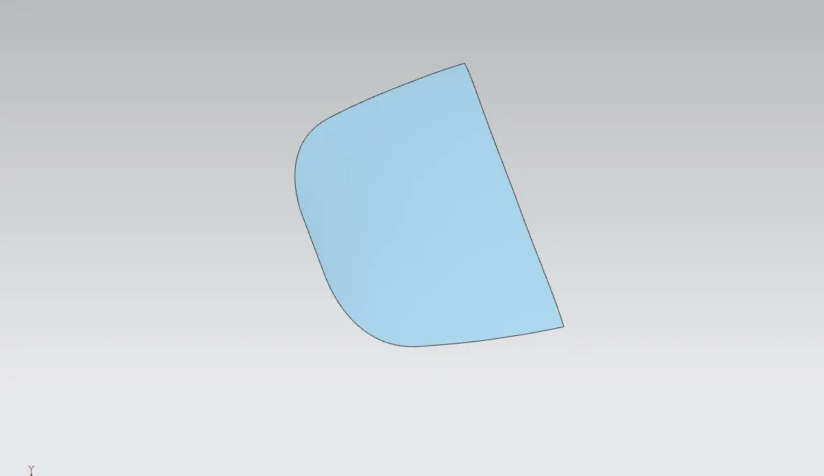
Inner_Hood_Panel:
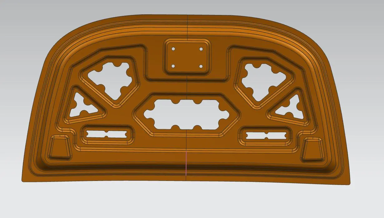
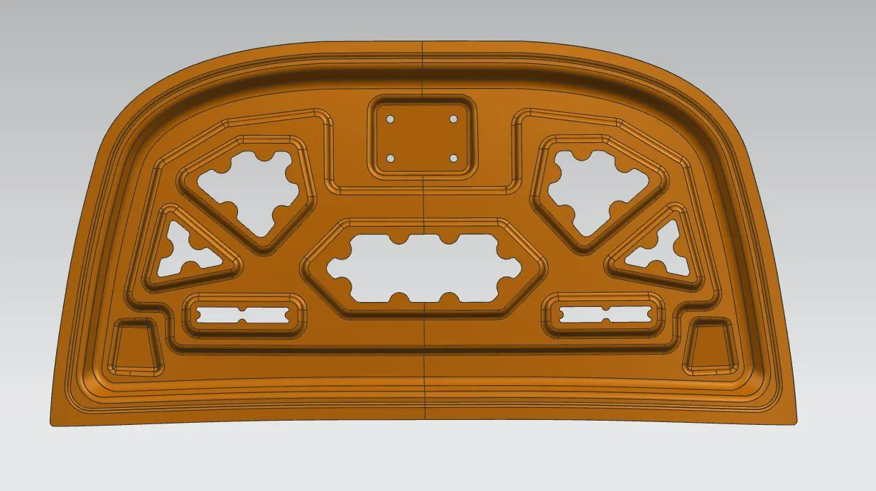
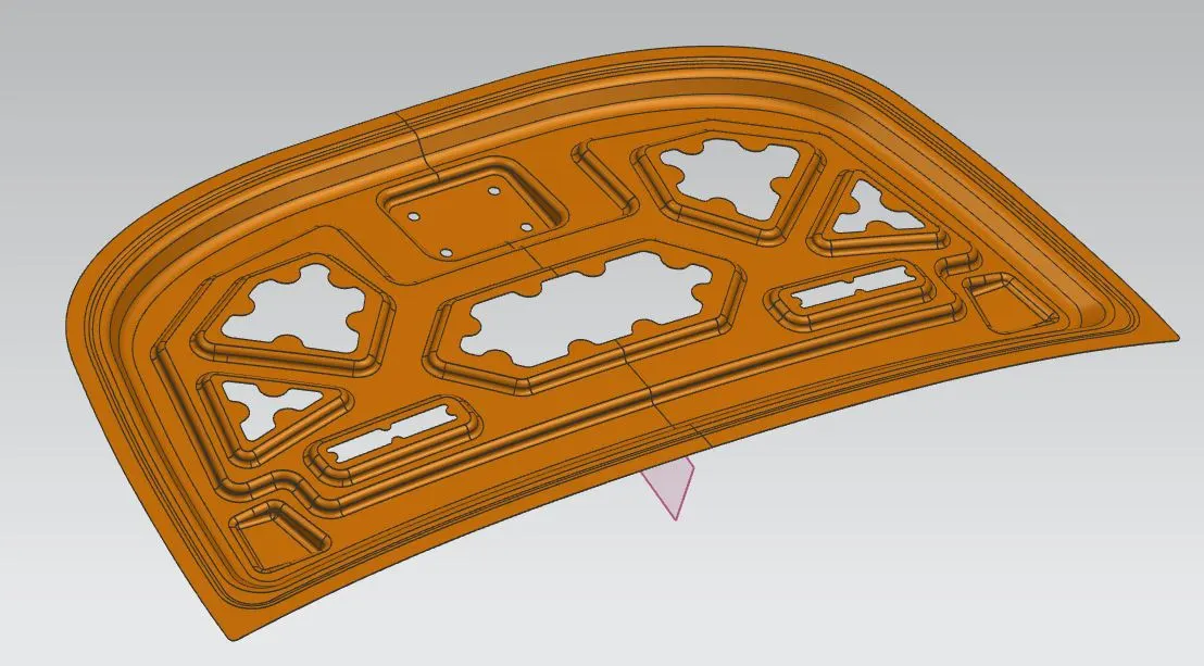
- In the inner panel only we can research & implement the safety of pedestrians & as well as the driver. In this panel only we can attach the reinforcement, embossed, mastic points, etc.
- It is an object of the present invention to provide a hood inner panel capable of reduction of a reaction force of the hood inner panel even if a level of deformation of a hood of a vehicle increases, & ensuring a sufficient energy absorption capacity.
First we want offset the surface to the inward direction by 1.7mm, 4mm, and 25mm. Then offset the curve in the surface and then trim off the surfaces to get the Flanges. By using the offset trimmed surfaces and then create intermediate surfaces by using the through curve option. Then finally we can uisng the blend options to join the surfaces in the right way to create the Mastic section inner panel.
Hinge_Assembly:
Hinge is a component that fixes the hood to the fenders of the car. The latch must be fixed perpendicular to the hinge axis so that the hood opens or closes properly.
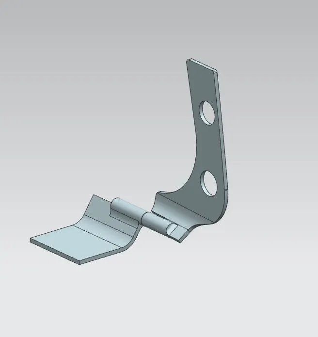
Hinge Positioning:
Hinge positioning is needed to be properly designed so that the opening and closing of the hood will occur correctly. Also, it will decide if the latch and striker get closed correctly or not.
To have proper hinge location, align hinges on the inner panel such that the midpoint of an axis passing through both hinges with striker center point be radius which will create a trajectory.
Mastic creation:
Mastic Data
To reduce NVH i.e. noise vibration and hardness between the hood inner panel and an outer one, mastic sealants are needed to be applied. Every mastic sealant improves the strength locally by around 80mm. It joins the inner panel with the outer panel also reducing the vibrating noise.
Thus while designing embosses on the inner panels we have to design mastic portions where sealant can be applied as shown in the image: Mastic Data.
Mastic regions are designed such that they will be closer to the outer panel. Rubber sealant is applied on the mastic regions of the Hood's inner panel which will glue both panels together.
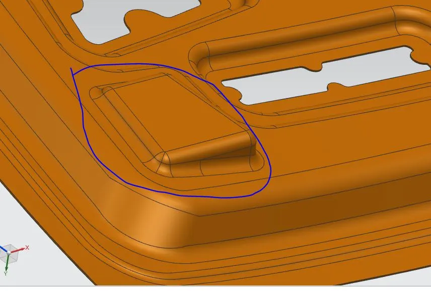
Striker Mount Emboss - Similar to hinge emboss we have to design Striker mount emboss to improve the local strength of the inner panel providing a support structure for latch mounting.
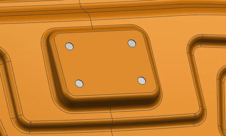
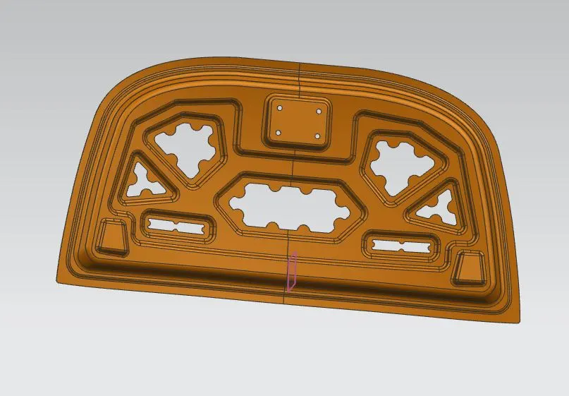
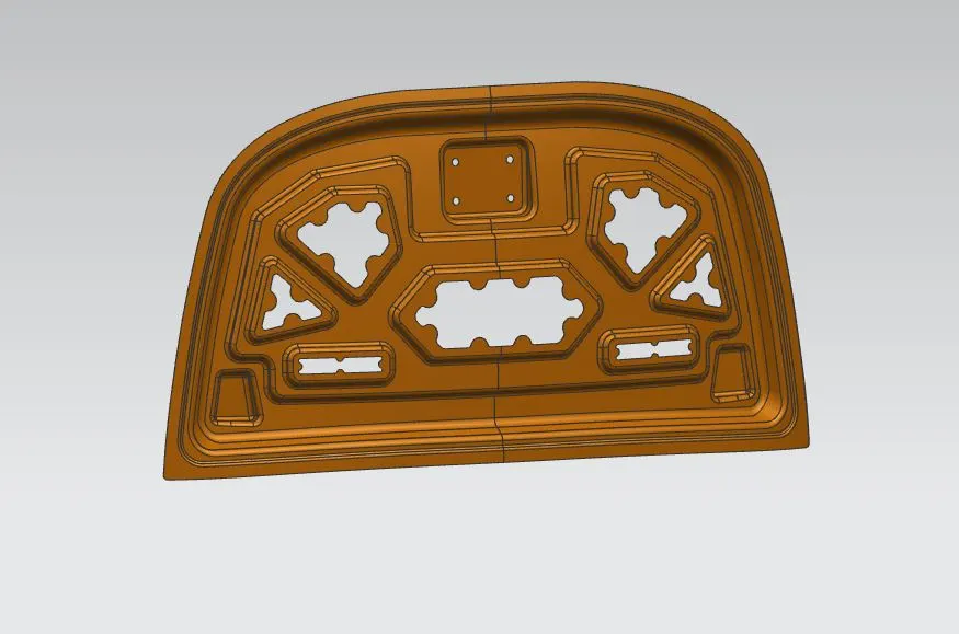
Final Inner Panel:
After creating all the mastic embosses on the inner panel then we can give the thickness to the panel. The final part will become like this,
Assembly :
After creating the inner panel in the required dimensions, then we can make the assembly and add the components on it, then give the constraints to it.
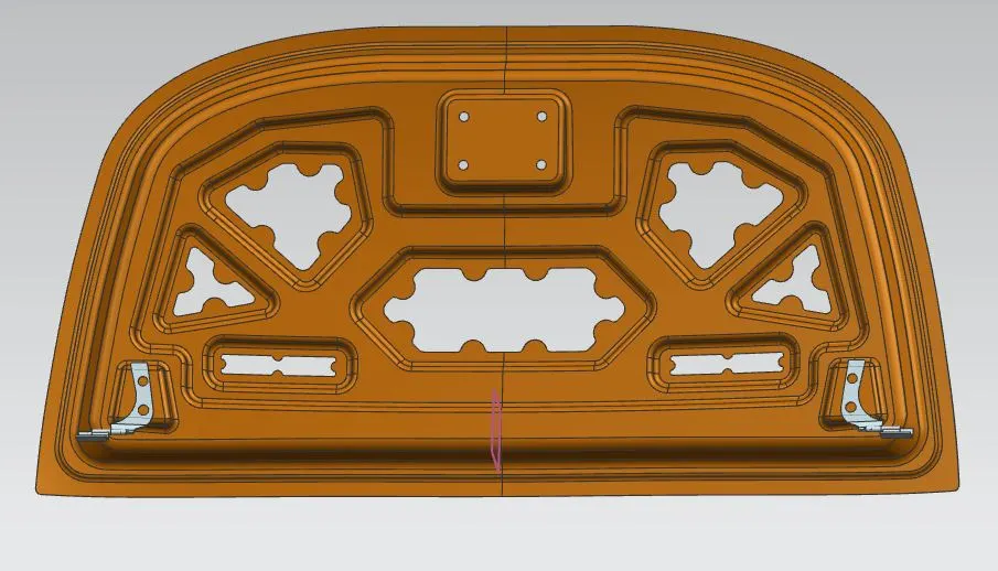
First we are going to add the hinge assembly, and make constraint as touch constraint to the back surface of the hinge with the hinge emboss on the inner panel. And another one constraint is given for make it parallel with the x axis. Then by using the move component tool, we can move to the required position of the assembly.
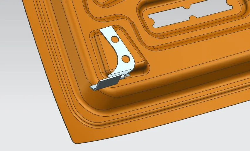
This hinge assembly is on the left side, and we want another one asembly which was present in the right side mount. So we are using the Mirror Assembly for mirror this assembly and made it as associative mirror.
Striker:
Latch & striker is used for locking the hood with the car. It is usually placed on the space provided on the inner panel.
We are having the striker in the download link. After adding it to the assembly, we can give give the constraints. But in this striker we are using the sketch for mounting it on the specific place. Because the hook is placced on the bottom position of the cavity in the car front area.
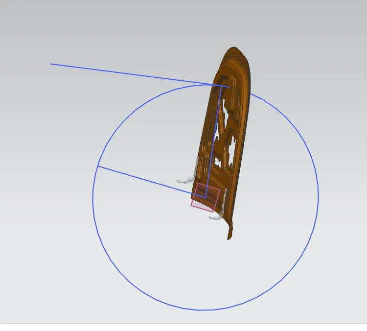
By using this sketch on the middle of the hinge axis plane, we create one circle for the downward direction of the door. The striker is tangential to the circle and perpendicular to that cavity present on the bottom portion.
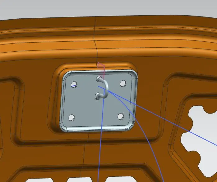
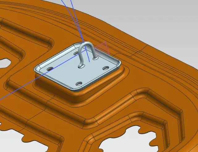
Therefore we are adding all necessary parts to the asembly, then we want to work on the outer panel hemming process.
Hemming-
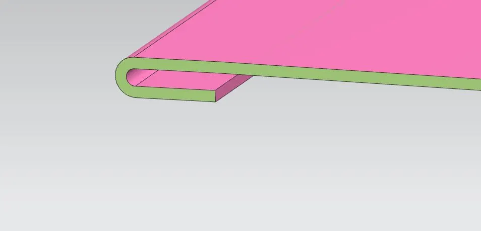
- Hemming is a sheet metal forming process in which sheets are joined by bending it usually to 180 degree. Automotive body panels & parts such as deck-lids, trunk-lids, doors, hoods & tailgates are formed by hemming processes.
- Roll hemming is carried out incrementally with a hemming roller. An industrial robot guides the hemming roller & forms the flange. Roll hemming operation can also be divided into several pre-hemming & final hemming process steps.
- Coventional die hemming is suitable for mass production. In die hemming, the flange is folded over the entire length with a hemming tool. Normally the actual hemming is a result of a forming operation in which the flange is formed with a hemming tool after the drawing & trimming operations have been completed.
Outer panel Hemming process:
Hemming Data:
We have the hemming data for creating the surface for the outer panel.
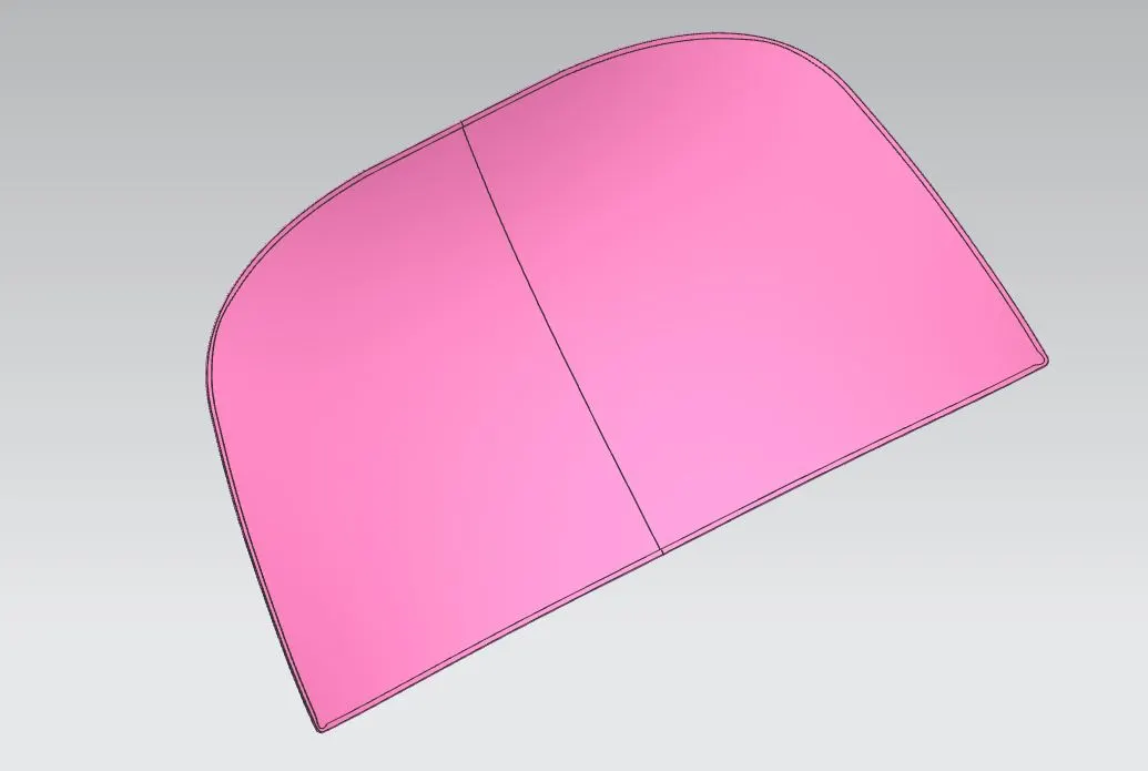
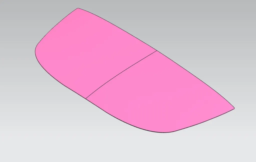
Here we use the offset surface to 2.65 mm and give the offset curve on surface to trim the bottom portion of the surface. Then by using the law extension, we can make surface perpendicular to the bottom and the top of the outer panel. After creating it we'll use the three face blend for getting the bend surface on the edges. It will create the smooth edge.
Edge relief:
Relief rear section:
Front relief:
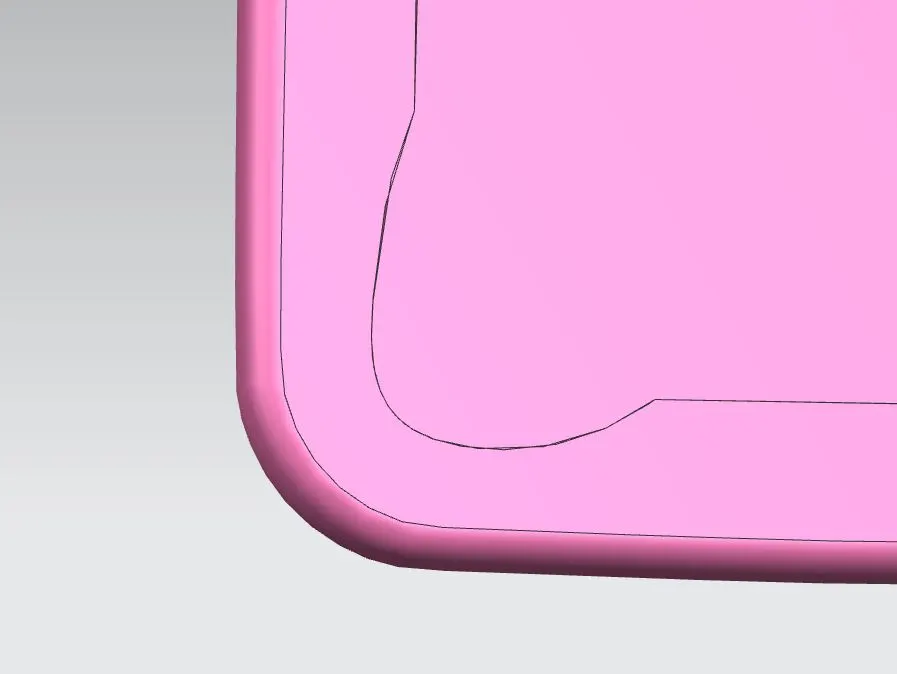
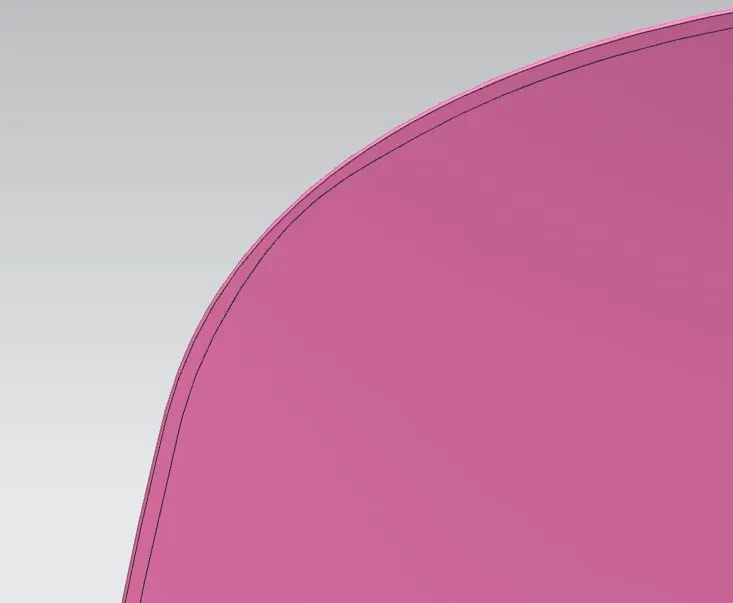
By using the curve on surface tool in the curves section, we can use theat to create the curves and then trim if off with the surface of the outer panel, later we'll get it like this panel.
After creating all the necessary dimensions on the panel we can give the thickness to the outer panel as 0.75mm.
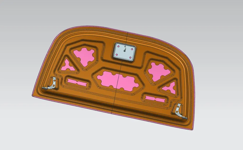
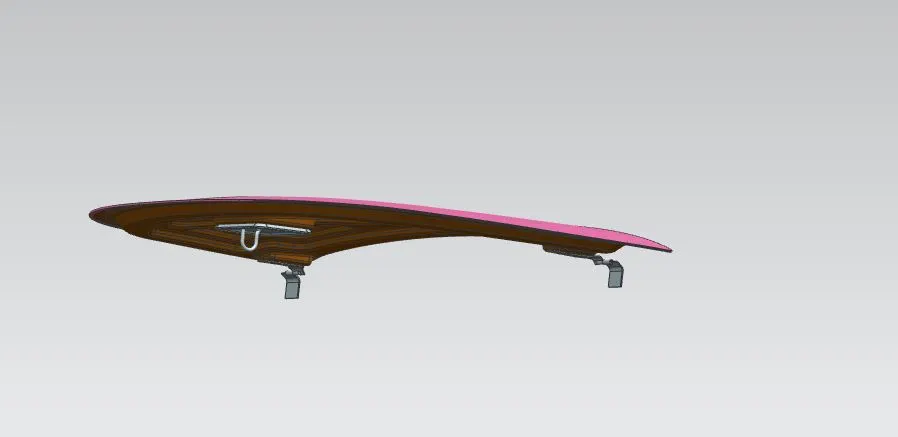
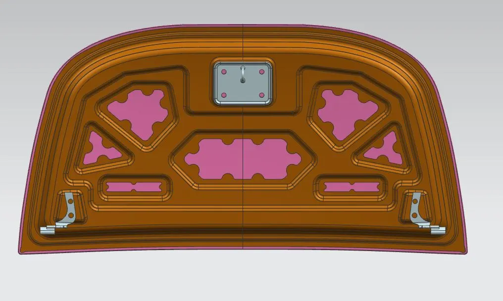
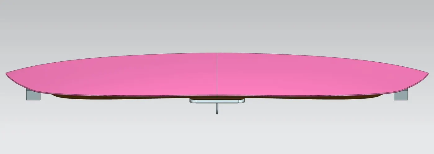
Final Assembly Output:
After adding all the necessary parts on the assembly we'll give the constraints to it to get the final assembly.
3D orientation of the Assembly:
Front View:
Top View:
Side View:
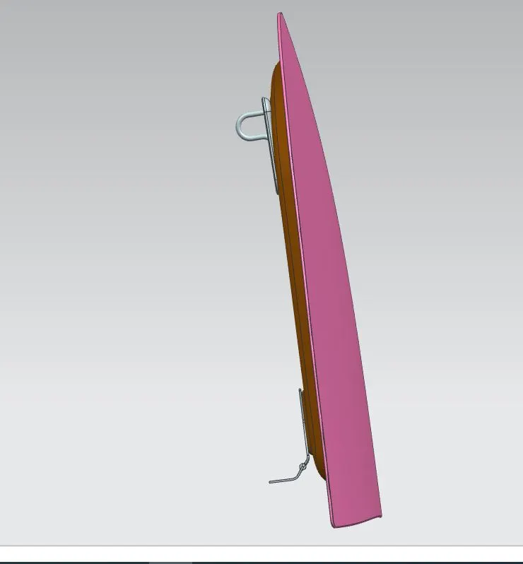
Isometric View:
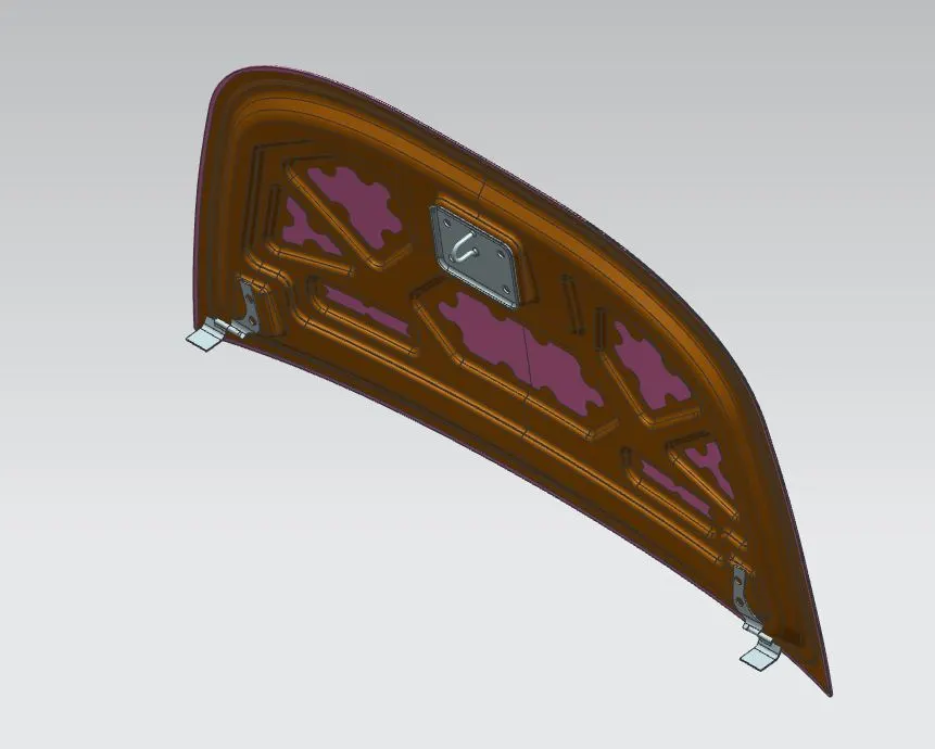
Cut Section for Checking:
So finally our assembly has the exact same clearance on the two surfaces on the Hood_Design_Assembly. It satisfies all the necessary requirements.