Hood design-Week 2
Hood Design Using Siemens Nx
Objective:
The Main objective is to design a hood inner panel, outer panel, positioning the hinge assembly, striker and its reinforcements with latch trajectory option using Siemens Nx application.
Introduction:
Here, we are going to study about how to create a hood inner panel, outer panel, positioning the hinges, striker and its reinforcements in siemens Nx Application. Using this application, how we are going to use tools step by step to complete the design. Then complete explanation about tools used to create hood and its safety considerations to be followed in designing a hood.
Hood:
A car hood, also referred to as a bonnet, is the hinged cover that rests over the engine of a front-engine vehicle. Its purpose is to provide access to the engine for repair and maintenance. A concealed latch is typically used to hold down the hood.
Points to be considered before designing hood:
- Opening angle of hood
- N CAP Crash Test
- Wrap Around Distance (WAD)
- NVH (Noise, Vibration, Harshness)
Opening Angle of Hood:
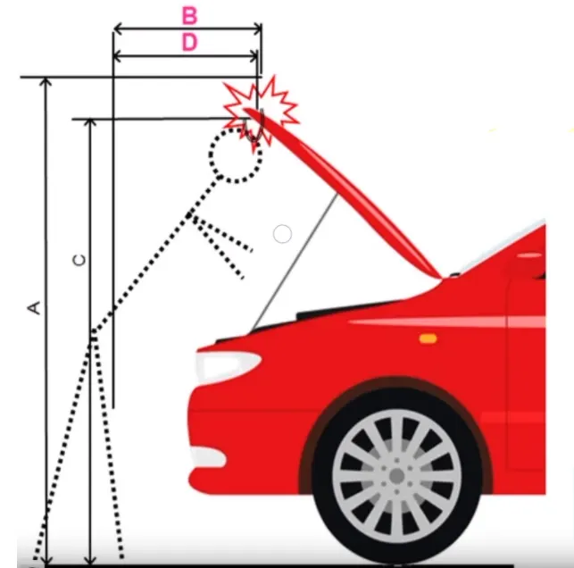
This is one of the main criteria in designing of the hood. This opening angle varies from person to person and country to country. For example, the average height of the Indians is 5.8 feet whereas in the European countries the average height will be 6 feet, based on these heights the opening angle may varies. The opening angle is considered important criteria because when the opening angle is less there is a chance of head injury to the human. The hood need supports to set an open angle according to the countries. There are two types of supports were there to hold hood. They are
- Support Rod
- Gas Stay
Support Rod:
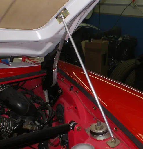
This support rod is quite simple in design and cheap in cost. This is widely used in many low budget cars. In this type, we have to lift the hood by ourselves and place the support rod in the space provided in the hood or engine compartment. In support rod, small bend needs to provide in the rod to strengthen the support rod. We need to consider this point into an account, the battery must be fixed in the engine compartment before providing space for support rod. If the above point didn’t consider, it results in failure, because we can’t able to access the battery part, because the rod will be hinderance to handle the battery.
Gas Stay:
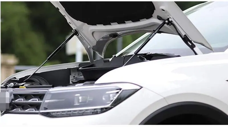
The gas stay is also used to lift the hood or bonnet automatically by means of gas pressure. Here, no man power required to lift the hood. This type is used where the car bonnet size is heavy to lift. The only disadvantage is costlier.
NCAP Crash Test:
Euro NCAP, or the European New Car Assessment Programme to give it its full name, is an independent crash-test safety body, which rigorously assesses the safety of cars, and helps to further the advancement of car safety technology. With safety at the forefront of all car makers minds, and many firms and organisations signing up to the ‘Vision Zero’ initiative – which aims to eliminate all deaths and serious injuries from our roads – Euro NCAP’s test programme is an ever-evolving one, with its architects periodically updating crash-test regimes to ensure cars are assessed using the most stringent criteria possible. The current Euro NCAP safety regime includes a dual rating, with cars tested both with and without various high-tech safety features. This means some cars may get five stars if they are configured with autonomous emergency braking, for example, but drop to four stars for the second rating if this feature is not standard.
Wrap Around Distance (WAD):
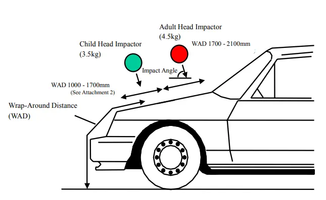
When a car crashes on the pedestrian, the whole human body wraps around the front shape of the car, and the head impacts on the bonnet or the windscreen. The distance at which the head impacts on the car from the ground is mentioned as wrap around distance (WAD).
To be specific the Wrap Around Distance is a measurement of the distance from the ground to the head impact zone over the outer surface of the car. The wrap around distance is measured longitudinally in the centre of the vehicle from the ground.
The severity of the injury caused by the frontal crash depends on the type and shape of the vehicle, the speed of the vehicle, and the movement of the pedestrian relative to the vehicle. In addition to these parameters, the wrap around distance plays a major role in the safety measures of a pedestrian.
During crash analysis, based on the wrap around distance, two test areas will be created namely the Child Head Impact Zone and the Adult Head Impact Zone.
Test Area:
- The child and adult head impactor test will be considered for the regulation.
- Test area for child head impactor: 1,000mm ≤ WAD ≤ 1,700mm
- Test area for adult head impactor: 1,700mm ≤ WAD ≤ 2,100mm
Impactor:
- Child head impactor: Diameter 165mm, weight 3.5kg
- Adult head impactor: Diameter 165mm, weight 4.5kg
NVH (Noise, Vibration, Harshness):
Noise, Vibration and Harshness (NVH) is the study and modification of the noise and vibration characteristics of vehicle, particularly cars and trucks. To improve NVH, mastic sealants were provided on the inner panel to attach with outer panel. Here mastic points on the inner panel plays a major role to avoid Noise and Vibration into the cabin. NVH is measured by the instruments, namely microphones, accelerometers and force gauges, or load cells. Component and subassembly NVH tests are most commonly performed using a vibration shanker while entire vehicles usually on the test track or road stimulator testbeds.
Design Methodology:
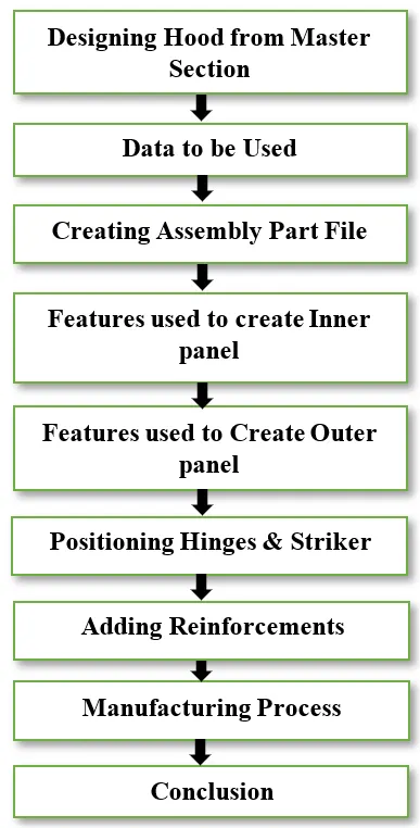
The design methodology of hood design is explained through flow charts.
Description:
Designing Hood from Master Section:
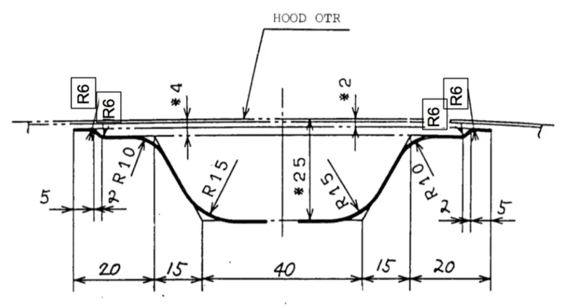
Master Sketch:
Data To be Used:
Hood Thickness Information
- Outer Panel Thickness = 0.75 mm
- Inner Panel Thickness = 0.75 mm
- Reinforcements Thickness = 1.5 mm
Creating Assembly Part File:
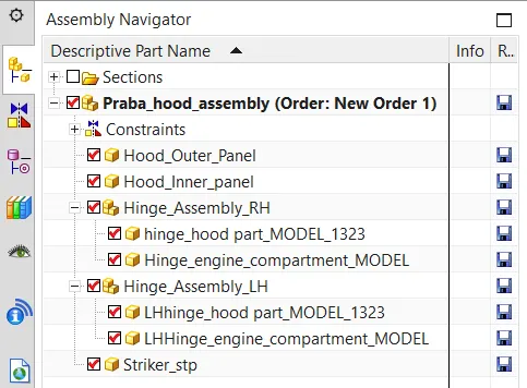
- Start Siemens Nx application to create assembly sheet. Then click ok to start design.
- Clicking on the assembly tab, importing the given parent files and assigning names to the part files in the assembly navigator section tab.
- Sample image were attached below for the reference.
Features used to create Inner Panel:
- Clicking on the Assembly navigator tab, double click on the create part file to start sketching.
- Clicking on the part navigator tab, creating the datum coordinate system to start inner panel design.
- Adding feature group name as Parent Geometry to secure the design.
- Again, extracting the body file from the parent geometry and adding feature group name as Working geometry.
- Trim body command is used to trim the body from imported part file to start creating inner panel.
- Offset surface command is used to offset surface. Clicking on the offset surface icon the dialog box appears. In that select face to offset at distance of 2 mm as per master sketch. Then Click ok to validate.
- Offset Curve in face command is used to offset one or more curves from the faces. By clicking on this icon, the dialog box appears. In that select face edges to select curves, provide offset curve distance to 13 mm, selecting face and providing radius as 20 mm in the fillet sharp corner. Then click ok to validate.
- Trim Sheet command is used to trim sheet bodies to intersecting faces and datums, and projected curves and edges. Clicking on this command trim sheet dialog box appears. In that select sheet body as target, select offset curve as boundary, select region as discard and click ok to validate.
- Again, clicking on offset surface icon to offset surface from working geometry at a distance of 4 mm downwards and click ok to validate.
- Same offset curve in face command is used and following the same steps but the offset curve distance changed to 20 mm and click ok to validate.
- Again, following the same trim sheet command procedure, here the region has to be changed to keep and click ok to validate.
- Through curves command is used to create a sheet body through multiple section where the shape changes to pass through each section. Sections are curves, points, solid edges, solid faces. Clicking on the through curves icon dialog box appears. In that select curves from trim sheet bodies, set Alignment as Arc length and click ok to validate.
- Again, offset the surface from the working geometry at a distance of 25 mm downwards and click ok to validate.
- Following the same steps mentioned above and setting offset curve distance to 43 mm and click ok to validate.
- Following the above trim sheet command and its procedure to get the required shape.
- Law Extension command is a powerful tool to create surfaces from curves, lines, faces and sheet edges. Clicking on this icon dialog box appears, in that select curves, faces and providing length law value as 45 mm, angle law value as 95 degree and extension side as one-sided. Then click ok to validate.
- Trim and Extend command is used to trim and extend one or more surfaces using a set of tool objects composed of edges or surfaces. Clicking on this icon dialog box appears, in that select trim & extend type as Make corner, select target as face of the second trimmed sheet and select tool as extended sheet. Then click ok to validate.
- Face Blend command is enhanced to provide a dedicated type for blending along intersection edges of bodies combined with a Boolean feature. It is primarily used to blend between faces of separate bodies. It can also be used to blend between faces of a single body. Clicking on this icon the dialog box appears, in that select Type as Two-face, select face 1 and face 2, provide radius of 6 mm. Then click to validate. Again, following the same steps to blend the faces to avoid sharp edges as per master sketch. The third applying face blend radius as changed to 15 mm and click ok to validate.
- Edge Blend command used to round sharp edges between faces. The radius can be constant or variable. Clicking on this icon the dialog box appears, in that select edges to blend and set required radius as 6 mm. Then click ok to validate.
- Sketch on the Front plane and create some shapes, which can stiffen the sheet body after embossing it. Make sure the sketch is fully constrained. Then click finish sketch to exit from sketch mode.
- Project Curve command is used to project drawn curves from datum plane to the required face, which is parallel to the datum plane. Clicking on this icon the dialog box appears, in that select drawn sketch curves and select face, specify vector as Y-axis, Projection direction as Along Vector and click ok to validate.
- Emboss command is a powerful tool to lift sheet material from projected sketches to form different shapes. Embossing is a metal forming process for producing raised or sunken designs or relief in sheet material by means of matched male and female roller dies, theoretically with no change in metal thickness, or bypassing sheet or a strip of metal between rolls of the desired pattern. The metal sheet is drawn through the male and female roller dies producing a pattern or design on the metal sheet. Depending on the roller dies used, different patterns can be produced on the metal sheet. Emboss should be in 7 degrees to 25 degrees incline in angle and it should not be in 90-degree angle, because when we do stamp in manufacturing process the stamping tool fits the sheet metal. Hence, it will not come out of that sheet metal. So, this is the main reason why the emboss face needs an angle.
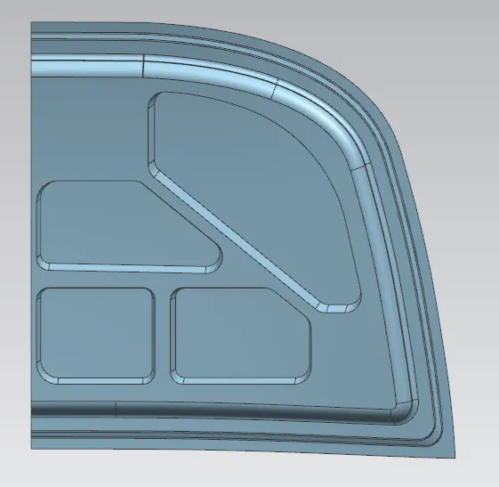
- Clicking on the Emboss icon the dialog box appears, in that select connected curves from drawn sketch, select face and direction, click End Cap Geometry as Embossed faces, set distance value as 22 mm, set draft angle as 10 degree. Then click ok to validate. Follow the same steps to complete the remaining sketch curves to produce emboss.
- Face Blend command is used to blend sharp corners to the embossed faces. Follow the same steps mentioned above and change the radius according to the required places.
- Again, sketch on the Front plane to make cut-outs on the embossed faces and providing space for Mastic sealants to attach with outer panel.
- By making cut-outs reducing the inner panel weight.
- Mastic Sealants is a type of liquid sealants that cures in an elastic state, thus making it flexible while holding the bond of the surfaces that have attached together. It adheres to just about any material making an all-purpose type of sealant. The main purpose of the outer panel is for aesthetic looks. Thus, we cannot use bolts or welding. This has to be done with the help of hemming and mastic sealants. Mastic sealants are elastic compound that behaves like the rubber. It is placed between the outer and inner panels. Initially is it in the paste form, but after the hot furnace bath, it gets hardened thus joining the outer and inner panel. Mastic sealant has the tendency to increase the strength of the panel and the influence of 80 mm diameter.
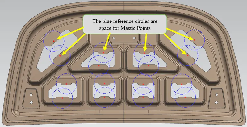
- Clicking on the Project curve icon the dialog box appears, select drawn sketch to project on face of inner sheet. Then click ok to validate.
- Clicking on trim sheet icon the dialog box appears, select sheet body as target, select sketched curves as boundary and specify region as keep. Then click ok to validate.
- Following the same steps for offset curve in face to the edge of inner panel to avoid sharp corners and providing offset curve distance to 3 mm.
- After finishing the above step and Trim sheet command is used to trim above offset curve. Then click ok to validate.
- Again, creating sketch on YZ plane. Draw an approximate length of parallel line to the inner sheet panel to create a plain surface using law extension command. This sketch is needed for hinge attachments.
- Creating sketch on XZ plane with some shapes. This sketch is used to create emboss for hinge attachments and hinge reinforcements.
- After creating emboss, face blend command is used to blend the sharp corners.
- Then creating hinge reinforcements to stiffen the inner panel sheet where the material loss occurs.
- Offset Curve command is used to take reference line from hinge attachment place and providing offset distance as 0.75 mm.
- Law extension command is used for the offset curve. Setting the length law as 70 mm and angle law as 0 degree. Then click ok to validate.
- Following the above two steps to get a required shape to attain hinge reinforcements. Providing 1.5 mm thickness to that reinforcement as per the given data.
- Clicking on the Assembly Navigator tab to unhide the Hinge assembly LH. Again, click on Part navigator tab, select assemblies tab. Click on Wave Geometry Linker to add sketches from other assembly parts. Clicking on circles taken from Hinge hood part model to the hinge reinforcements. Trim sheet command is used to make holes in the hinge reinforcements.
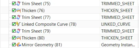
- Thicken command is used to add thickness to the sheet metal. Clicking on the thicken icon the dialog box appears, selecting face to be thicken of 1.5 mm and click ok to validate.
- Edge blend command is used here to eliminate sharp corners and providing radius value as 5 mm after selecting the edges.
- Following the same procedure to create point on the hinge axis by selecting centre circle in the hinge assembly.
- Mirror Geometry command is used to copies geometry and mirror them across a plane. Clicking on this icon, select the whole body to mirror in YZ plane. Then click ok to validate.
- Examine Geometry command is used before Sew command to examine the mirror geometry. If any problem occurs at mirror geometry, we can identified through examine geometry method. After that we can solve the problems faced in joining of inner panel.
- Sew command is used to combine sheet bodies by sewing common edges together, or combines solid bodies by sewing common faces. The selected sheet bodies must not have any gaps larger than the specified tolerance.
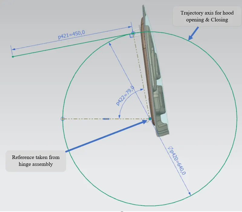
- Creating circle with the help of point created on the YZ plane. Here Latch trajectory method plays a major role to position the striker and hinge assemblies in perpendicular axis.
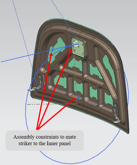
- Top of the circle, creating tangent line and adding striker to the inner panel through wave linker geometry option. Creating perpendicular line on the striker. Clicking on the geometric constraints icon to align striker to the inner sheet in correct position.
- With the help of striker position, offset the base face of striker to create emboss in the inner panel.
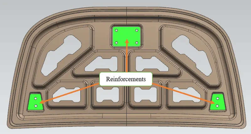
- Adding striker reinforcement to the striker. Adding thickness to the striker reinforcement as 1.5 mm as per given data.
- Thicken command is used to thicken the sheet material. Clicking on this icon the dialog box appears, in that select sew body to be thickened at the thickness of 0.75 mm as per master sketch.
- Attaching reference part navigator images.
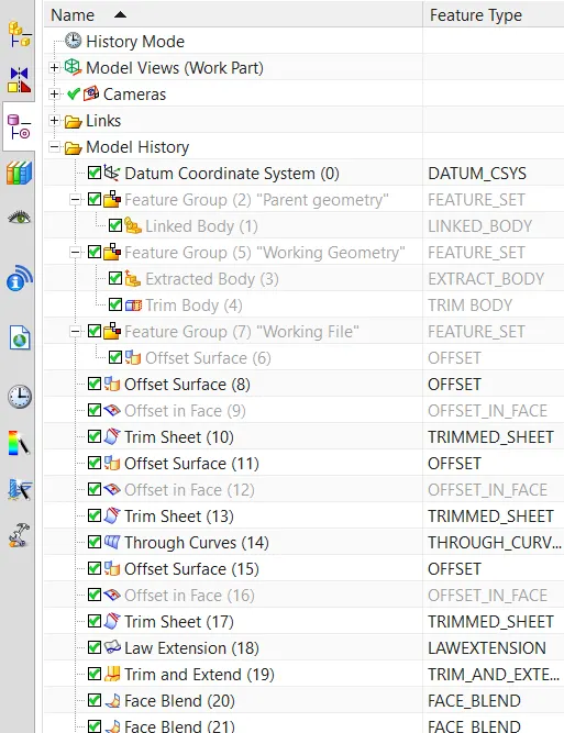
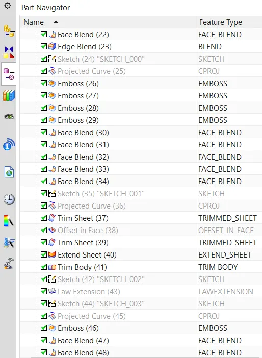
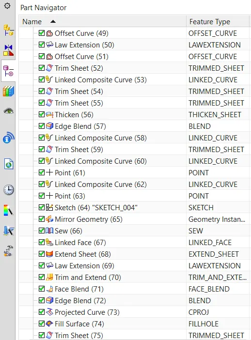
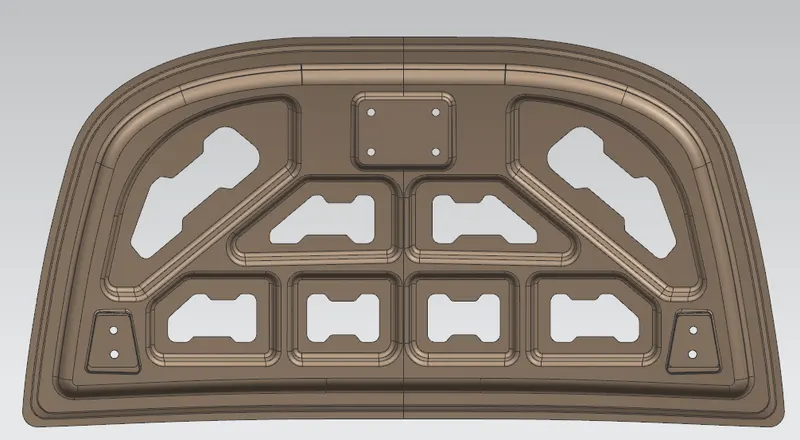
Front View of Inner Panel:
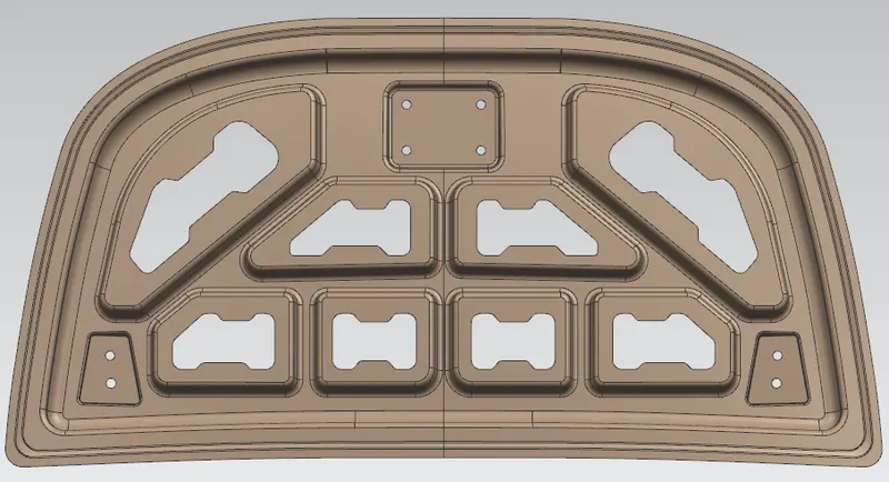
Back View:
Top View:

Bootom View:

Isometric View:
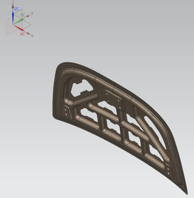
Finally, the inner sheet design was completed.
Features used to create Outer Panel:
The outer panel is nothing but the outer skin of the inner panel. Otherwise called as a cover of the inner panel. It is the part, which gives luxurious look to the hood or bonnet. The outer panel and inner panel cannot join by any welding process like spot welding or rivet, which spoil the outer look of the car.
The following commands were used to complete the outer panel design and attaching the image for the reference.
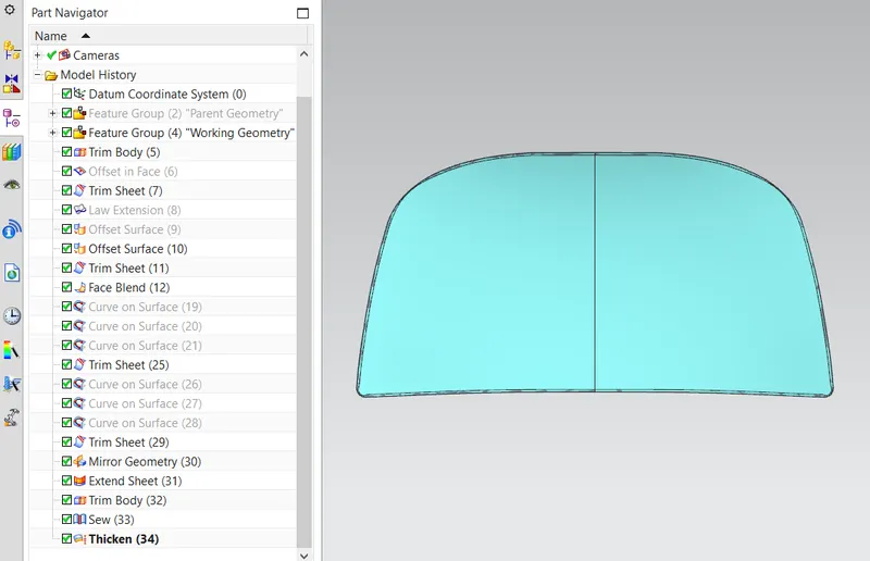
- Clicking on the part navigator tab, creating the datum coordinate system to start outer panel design.
- Adding feature group name as Parent Geometry to secure the design.
- Again, extracting the body file from the parent geometry and adding feature group name as Working geometry.
- Trim body command is used to trim the body from imported part file to start creating outer panel. Clicking on the trim body icon the dialog box appears, in that select sheet body as Target and specify plane as XC, reverse direction and click ok to validate.
- Offset Curve in face command is used to offset one or more curves from the faces. By clicking on this icon, the dialog box appears. In that select face edges to select curves, provide offset curve distance to 0.5 mm, selecting face and providing radius as 20 mm in the fillet sharp corner. Then click ok to validate.
- Trim Sheet: Clicking on this command trim sheet dialog box appears. In that select sheet body as target, select offset curve as boundary, select region as discard and click ok to validate.
- Law Extension: Clicking on this icon dialog box appears, in that select curves, faces and providing length law value as 15 mm, angle law value as 80 degree and extension side as Symmetric. Then click ok to validate.
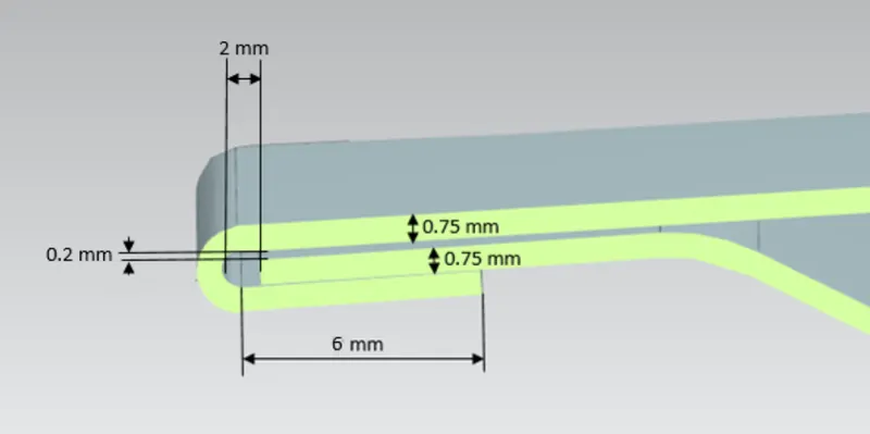
- Offset surface: Clicking on the offset surface icon the dialog box appears. In that select extended face to offset at distance of 6 mm as per master sketch. Then Click ok to validate.
- Again, clicking on the offset surface icon the dialog box appears. In that select face to offset at distance of 2.95 (0.75+0.2+0.75+0.75+0.5) mm as per master sketch. Then Click ok to validate.
- Trim Sheet: Clicking on this command trim sheet dialog box appears. In that select sheet body as target, select offset curve as boundary, select region as discard and click ok to validate.
- Face Blend: Clicking on this command trim sheet dialog box appears, in that select Type as Three-face, select face 1 as bottom 6 mm trimmed surface, face 2 as top surface and middle face as extended faces. Then click ok to validate.
- Hemming Process: Hemming is a forming operation in which the edges of the sheet are folded over another part in order to achieve a tight fit. Normally hemming operations are used to connect parts together, to improve the appearance of a part, and to reinforce part edges. Conventional die hemming.
- Hemming is the process in which the edge is rolled flush to itself, while a seam joins the edges of two materials.
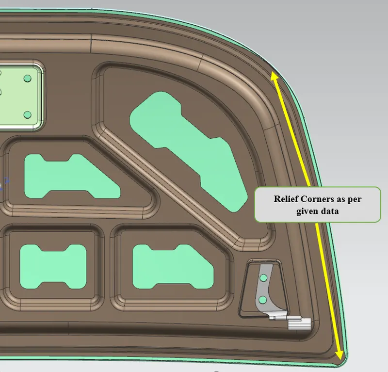
- Curve on surface command is used to relief corner on the hemming process. Clicking on this icon the dialog box appears, in that select face and spline constraints as specifying two G1 points on the face to make an arc.
- Trim sheet: Clicking on this command trim sheet dialog box appears. In that select sheet body as target, select offset curve as boundary, select region as keep and click ok to validate.
- Again, same steps were followed for curve on surface and trim sheet command to make a corner relief on the upper corner of outer panel.
- Mirror Geometry command is used to copies geometry and mirror them across a plane. Clicking on this icon, select the whole body to mirror in YZ plane. Then click ok to validate.
- Examine Geometry command is used before Sew command to examine the mirror geometry. If any problem occurs at mirror geometry, we can identified through examine geometry method. After that we can solve the problems faced in joining of inner panel.
- Sew command is used to combine sheet bodies by sewing common edges together, or combines solid bodies by sewing common faces. The selected sheet bodies must not have any gaps larger than the specified tolerance.
- Thicken command is used to thicken the sheet material. Clicking on this icon the dialog box appears, in that select sew body to be thickened at the thickness of 0.75 mm as per master sketch.
Sreen Shots of Outer Panel Views:
Front View:
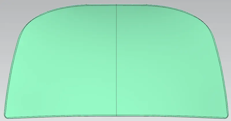
Back View:
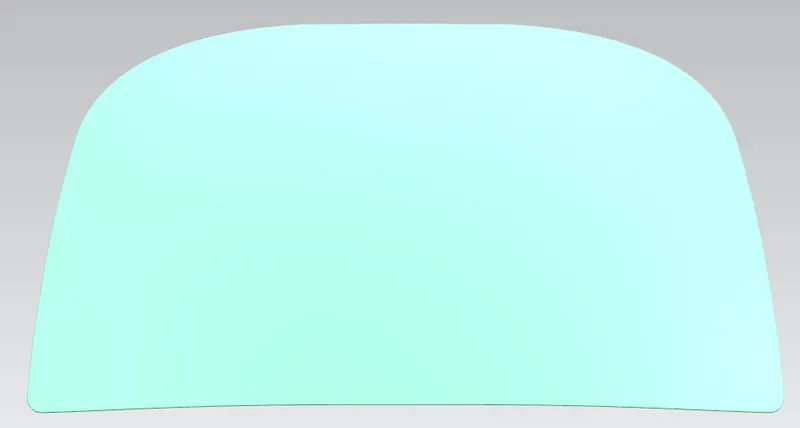
Top View:

Bottom View:

Right Side View:
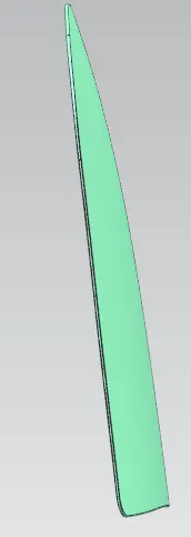
Isometric View:
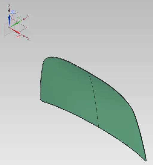
Finally, the outer panel design has been completed.
Positioning Hinges & Striker:
For the proper opening and closing of the hood, the striker should be perpendicular to the trajectory of the hood. For this, the hinge is to be assembled at its position. After placing hinge assembly at one position, adding wave geometry linker to select mid circle on the hinge assembly to create centre point in it. Using that point creating a circle on the YZ plane to position the striker to the perpendicular of hinge axis. The detailed explanation is given above in creating inner panel section. Here, attaching the reference image.
Assembly Striker Constraints:
Adding Reinforcements:
Adding Hinge reinforcements and Striker reinforcements are mainly used to compensate loss occurs at the hinge & striker areas. The material loss information was got from CAE team. Material loss can be compensated by adding reinforcements to the hinges & striker parts.
Manufacturing Process:
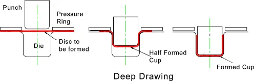
- Deep drawingis a sheet metal forming process in which a sheet metal blank is radially drawn into a forming die by the mechanical action of a punch. It is thus a shape transformation process with material retention. The process is considered "deep" drawing when the depth of the drawn part exceeds its diameter.
- We give a positive draft or an angle for a better drawing process.
- Deep drawing processes are divided into three types:
- Deep drawing with tools
- Deep drawing with active means
- Deep drawing with active energy
Hemming Process:
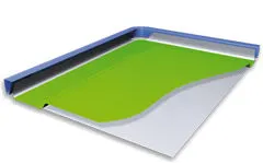
Hemming is a forming operation in which the edges of the sheet are folded over another part in order to achieve a tight fit. Normally hemming operations are used to connect parts together, to improve the appearance of a part, and to reinforce part edges. Conventional die hemming. Hemming is the process in which the edge is rolled flush to itself, while a seam joins the edges of two materials. In hood Design, hemming is used in assembly as a secondary operation after deep drawing, trimming ang flanging operations to join two sheet metal parts (Outer and Inner) together. In between the outer and inner panel, there will be gluing after or before the hemming process because to reduce NVH and also sticking the two panels.
Types of Hemming:
Conventional Die Hemming: The Flange is folded over the entire length with a hemming tool.
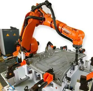
Roll Hemming: The hemming roller is guided by an industrial robot to form the flange. For manufacturing the hood, we choose Roll Hemming process for smooth finishing.
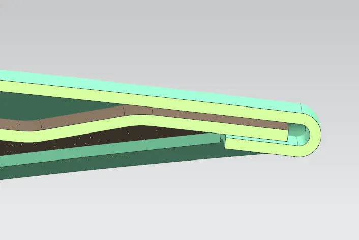
Hemming parameters:
Relief Corner:
Relief is provided onto the part in order to remove any stresses developed in a particular area, i.e., sharp corners that take place during hemming processes are carried out. Thus, corners are rounded or chamfered. Here, we are leaving 2 mm from sheet metal edge for roll hemming process.
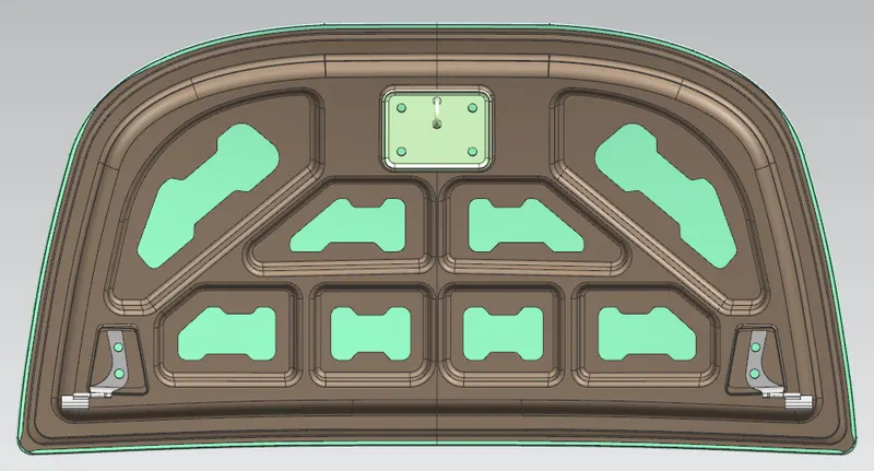
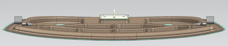
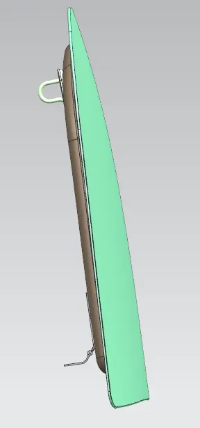
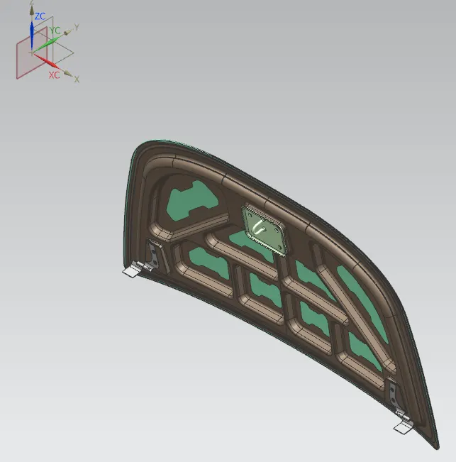
Hood Assembly Views:
Front View:
Back View:
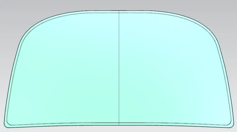
Top View:

Bottom View:
Right Side View:
Isometric View:
Conclusion:
Finally completed the Hood Design using Siemens Nx application as per the Master sketch and design parameters provided to complete design.