Hood design-Week 2
REPORT ON HOOD DESIGN .
AIM: TO CREATE THE HOOD INNER PANEL ACCORDING TO THE MASTER SECTION AND THE REINFORCEMENTS AND DRAWING THE LATCH AND STRIKER TRAJECTORY AND ASSEMBLING THE STRIKER AND HINGE ASSEMBLY.
PROCEDURE: First we will recieve a hood outer panel from that we have to create the inner panel and neccessary things. the picture of hood outer panel iss as follows:
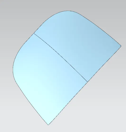
from this we have to make the inner panel. tonot make things complicated we have to trim outer panel into two so we will use trim command to trim the outer panel and we will recieve the output as follows:
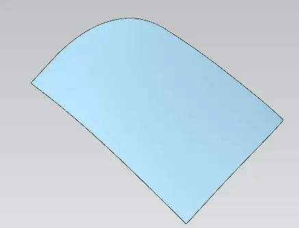
so our first step will be we will do the wave geometry linker and then we will hide the outer panel and then we will first offset the surface to 1.7 mm as per the master section and then we will offset curve in face to get the first layer of the inner panel and we will offset the curve to a distance of 20 mm and then we will do the trim and then we will get the outptu as follows:
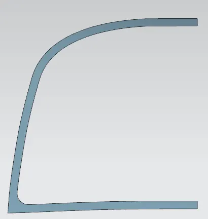
but here we will get an sharp edge inside to avoid that we will do the best fit option while doing the offset curve .
after getting the first layer we have to get the second layer and the 3rd layer to get those layer we will follow the same procedure as we did for the first layer just we will change the values of the offset curve.
after getting all the layer as per the master section we have to create one more surface which will close the 1st and 2nd and 3rd layer to create that surface we will use through curve command and we will recieve the output as follows:
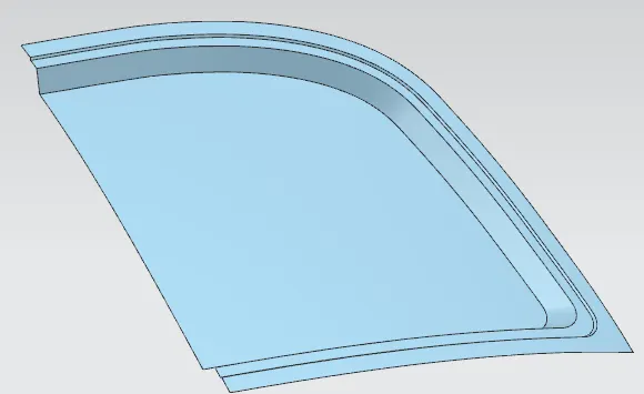
after getting the inner panel as per the master section we have to create embosses to strengthen the inner panel but before creating the emboss we have to do the blends for the corner a per the master section so for creating the blend we will sew all the layers and make it as a single component and then we will use the edge blend as we will give the radius value as per the master section and we will recieve the out put as follows
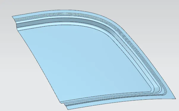
after getting the output as above image we will hav eto create the embosses for creating the emboss first we have to know that the minimum distance between the edge of the 3rd layer and the emboss should be 6-8 mm so we will offset the curve in face to a distance of 6 mm and we will recieve an output as follows:
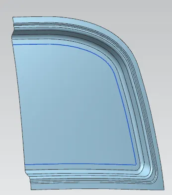
after getting the output as above image we have to create the emboss sketch.
to create the sketch we will go to sketch option and then we will selct the required plane and then we will do the sketch as per the ofset curve and we have to leave gap for striker emboss and the hinge emboss for leaving that gap first we have to measure the striker length and breadth and the hinge length and breadth and then we have to create a sketch in such a way the striker emboss and the hinge emboss will have required gap and an extra space of 6-8mm for clearence and we will recieve an output as follows:
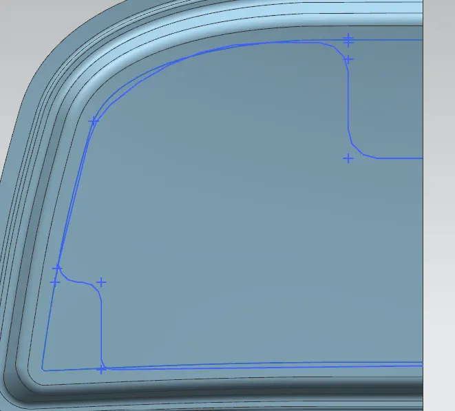
but the sketch which we created is not on the surface it on the plane but we want it on the surface to get it on the surface we will use 3D project curve command and we will project our sketch on the surface and then we will use emboos command to create the emboss but here we have to give draft and the height of the emboss as per our instruction the draft for sheet body is going to be more than 7 degree and the height of the emboss is our wish but we have to create two emboss primary emboss and the secondary emboss the both emboss height should be 18.5 why because the thickkness of our inner and outer panel should 0.75 mm and the gap for mastic sealents should be 5 mm keeping in mind all these things we have to give the height for emboss so here we have created the primary emboss to a height of 10mm and our out put will be as follows:
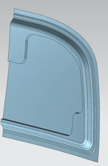
after getting the primary emboss we should give blends for it also and the blend value is 3+the thickness of our component so that the blend value is 3.75 m radius and ou output will be as follows:
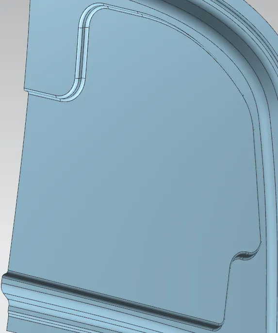
after craeting the primary emboss we have to create the secondary emboss on the primary emboss the secondary emboss shape is not given so we can create as we want and the creating methods all same as the primay emboss including blend value on the height should be 8.5 mm.
after creating the secondary emboss we have to create the cutout on the secondary emboss so to create cutout we have to do the sketch in such a way that we have to provide semi circles for the masrtic sealents and after creating tthe sketch we have to trim sheet with the sketch and our output will be as follows:
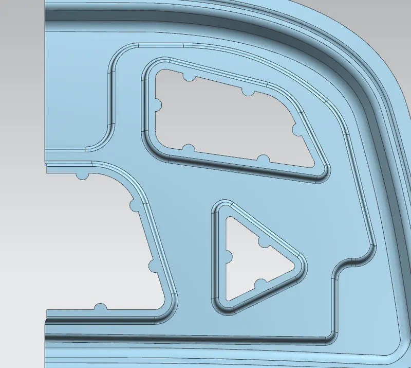
afteer creating cutouts on the secondaary emboss we have to create the hinge emboss on the other side for creating the hinge emboss we will create a datum plane which is from the surface at a distance of 6-8 mm and then we have to claculate the hinge l*b and then we have to make a sketch and we will project and we will use emnbosss command to create the hinge emboss but we have used embossed face in previous embosses but here we will use upto datum plane and we have to give the blend valuse as same as the previous embosses and then we will recieve output as follows:
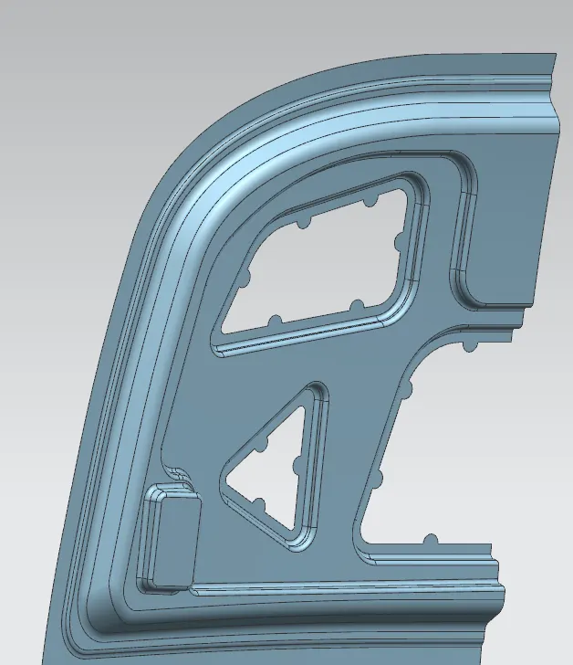
after creating upto this much our inner panel is 90% ready.
after getting the hinge emboss we have to create the striker emboss but before that we have to extend our sheet a little bit and then we have trim the sheet with respect to a middle plane and then we have to mirror geometry the inner panel and we have sew them to make single component and we will recieve the output as follows:
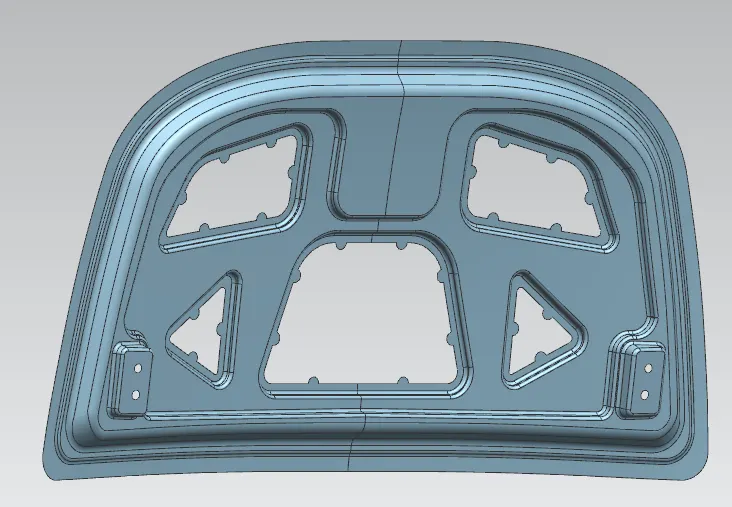
after getting this much we have create the striker emboss for creating the striker emboss we have apply latch and striker trajectoy to make the striker perfectly lock.
but before creating all these we have assemble our hinge assembly to the hinge emboss and then we have to create the latch and striker trajectory
after assembling the hinge assembly perfectly we have to create a point on the hinge circle and then we have to create the line on the two points of the hinge assembly and then we have to create a mid point between those two points and then we have calculate the claearence and the measurement of striker and then we have to create a perpendicular line upto the claculated distance and then we have to create a centre point circle we have to use the mid point between the two points as the centre point of the circle and then the radius should be upto the end of perpendicular line after thet we have create one more line tangent to the circle form the striker and our output will be as follows:
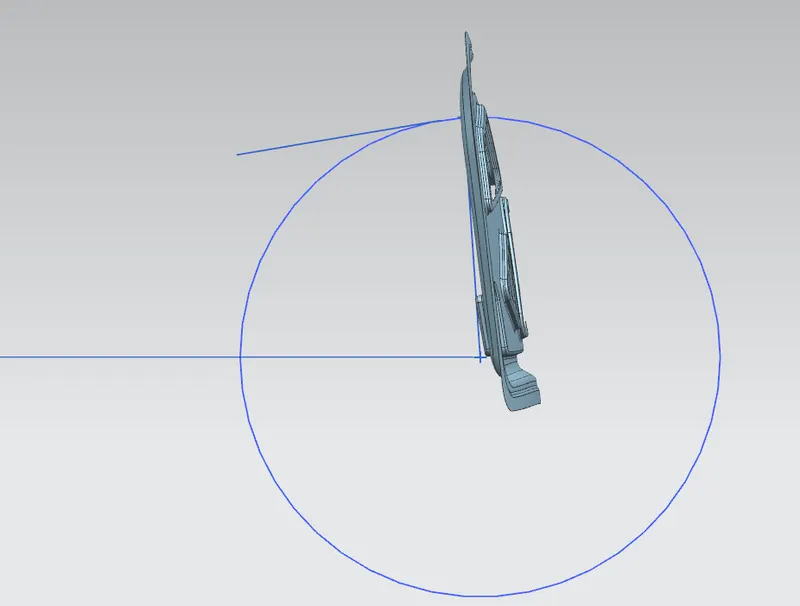
after this we have to move our striker perfectly to the circle and the tangent line and our out put will be as follows:
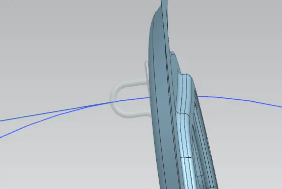
after this we have to create the striker emboss for creating it we will do wvae geometry linker for the base of the striker and then we will hide the striker and then we will extend the the base upto 3 mm and then we will use law extension on the curves of the extended surface and then we will sew the law extension and the extendes surface and we will use the trim and extend command on the sew of extended surface and the law extension and the inner panel and we will recieve the output as follows:
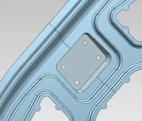
after this we will give blend to the sharp edges and then we will give reinforcement to the striker emboss and the hinge embosses.
for giving reinforcement we will simply extract base of the inside of the striker and hinge emboss and then we will thicken it as per the requirement.
once if we completed this much our inner panel is ready.
after getting the inner panel ready we have to focus on the outer panel the outer panel should cover the inner panel as per the master section.
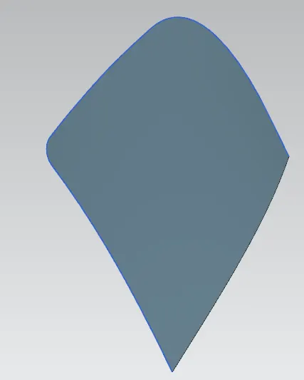
so first we will offset the curve in face of the outer panel and then we will offset that curve to a 0.5mm distance to get a curved surface and we will trim the sheet and we will recieve the output as follows:
after getting this we have to create the other surface which is the hemming surface for creating it as per the master section it is offset at a distance of 0.75+0.2+0.75+0.2+0.75 mm and the curve is offsetted at a distancee of 6 mm so we will offset the surface to the required distance and then we will offset the curve in face to a distance of 6 mm and then we will trim shett and our output will be as follows:
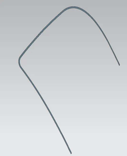
after getting this we want another surface which is wrapping the two surface to create that surface we will do the law extension the first surface and then we will apply three face blend to all the three faces and we will recieve the output as follows:
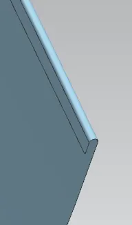
after getting the wrapped surface we will extend the sheet upto a distance of 3 mm and we will trim sheet and then we do the corner relief for corner relief we will do the sketch on the rquired plane and the project the sketch on the suface and trim sheet after this we will do the mirror geometry and then we will sew thgem to make it as single component and we will recieve the output as follows:
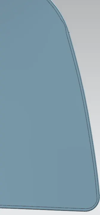
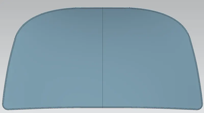
after getting this we will thicken our outer and the inner panel and then we will assemble all the parts and we will recieve the output as follows:
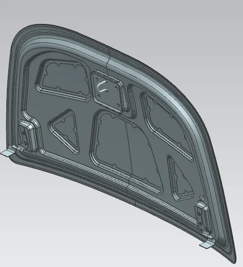
once if we get the output as above image ou component is ready.
NOTE: KINDLY OPEN AND SEE THE FILE