Hood design-Week 2
Hood Design
Objective:
To create a detailed 3D model of Automobile Hood using siemens NX.
Introduction:
In this project a detailed model of an automobile hood is created using Siemens NX in-order to understand and familiarize with different tools and methods of modelling. Hood is an important part of an automobile as it provides safety to the passengers. The hood is designed in such a way that on impact on the front of the car would redirect the forces away from the passengers. The hood panel consists of three main components.
- Inner panel: Inner panel is the main component of the hood as it is designed for dissipating the force of impact to the side of the automobile body. The inner panel consists of the reinforcements as well as the mastic points.
- Outer panel: The outer panel serves as an aesthetic component while also providing extra strength to the inner panel. The curvature of inner panel is based on the design of the outer panel.
- Reinforcements: The reinforcements provide additional strength to the inner panel at the points where other components such as the latch and hinge will be placed. These reinforcements ensure that the hinges and the latch have better support to avoid failure.
Design Methodology:
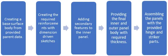
Description:
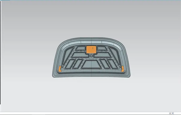
The hood design along with the inner and outer panel has other important parts such as the latch trajectory, the mastic points and reinforcements.
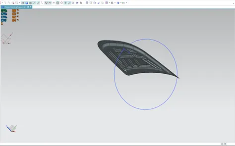
- Latch trajectory:
The latch trajectory shows the path of the striker when the hood is opened and closed on a vehicle.
The radius of the circular trajectory is determined by the set standard based on the average height of a person. The radius is measured from the hinge axis up-to the latch.
- Mastic points:
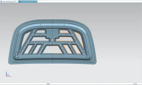
The mastic points are areas where the mastic is placed to attach the outer panel to the inner panel. We cannot use spot welding as it would give a less aesthetically pleasing result. Hence mastics are used to join the panels together as it does not melt the metal itself.
- Emboss Definitions:
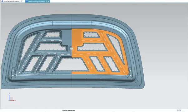
The inner panel consists of various embosses which help dissipate the force during impact.
The width and depth of the emboss is determined by simulations and analysis to check for failure.
These emboss definitions are created at an angle so that they point away from the centre of the hood when viewed from the front of the vehicle.
- Reinforcements:
The area near hinge and latch has more chances of failure in the hood panel. Hence to avoid any failure, the hinge and latch areas are reinforced with extra material whose thickness is usually determined by the type of vehicle.
To produce the hood in a manufacturing plant various processes are used. A few of these processes are deep drawing and hemming.
- Deep Drawing: In this process a sheet is drawn to desired shape using a punch and die apparatus. The sheet is forced into the shape of the die by forcing the punch down on it. To avoid the sheet to fold on itself, the sides of the sheet are held down by binders.
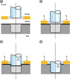
This process is the most common and efficient process in automobile manufacturing industry.
- Hemming: The hemming process is used to lock two sheets together by folding one sheet around the other sheet. The hem is created by first creating a perpendicular flange. The flange is then bent beyond 90 degrees in pre-hemming process. Finally the hem is created by pressing the flange back on the sheet completely. Hems can be open type or closed type. To lock two sheets together, generally open flanges are used.
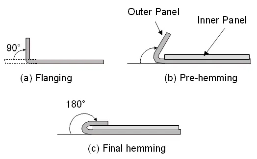
To create these hems and drawn surfaces in a 3d software, we use features such as emboss and offset surface.
The hood design requires designing the outer panel, inner panel and the assembly. We use Siemens NX for creating the complete model of the hood.
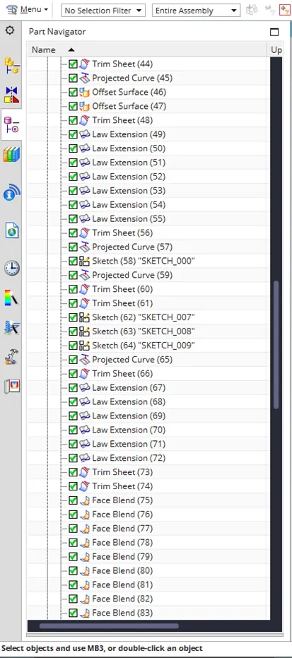
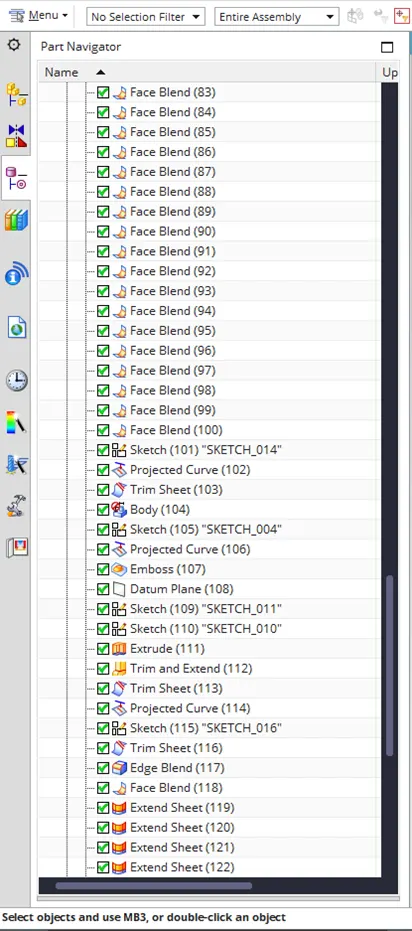
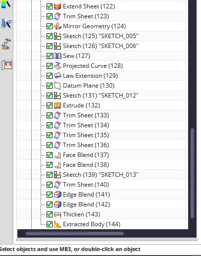
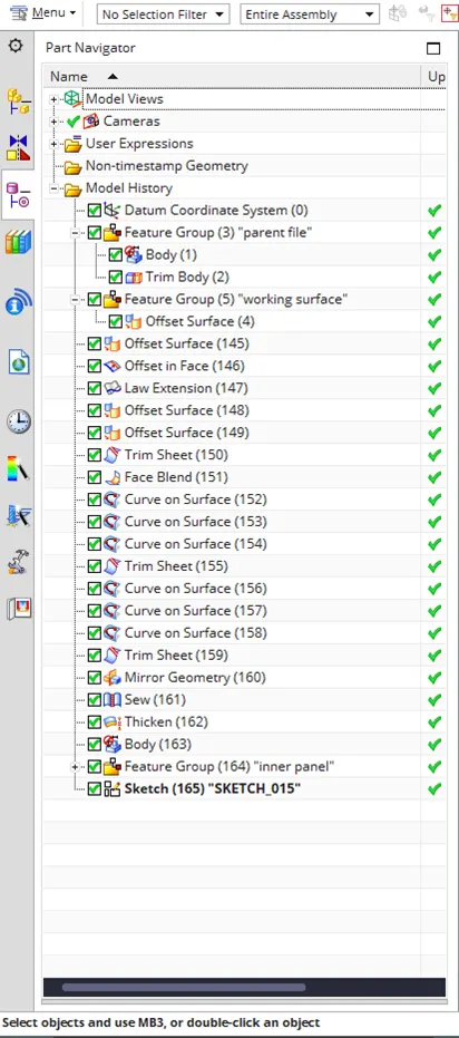
Below are the features used in creating all the parts of the hood design.
- Offset surface: The offset surface tool creates a copy of the selected surface at a provided distance and direction.
- Emboss: The emboss tool creates a punched surface of the selected closed contour. The punch is created from a selected surface containing the contour sketch/curve. A draft can be provided for the punch from either the end cap or the base surface.
- Trim sheet: The trim sheet tool splits the target surface along the intersection curve of target surface and the tool surface. The part of surface on either side of the intersection can be either discarded or retained as per the requirement.
- Through curves: This tool creates a surface between two different surface sections where the shape can change in between sections.
- Law extension: Creates an extended surface based on an open chain contour or a closed contour on the selected target surface. A draft can be provided for the extension.
- Face blend: Creates a curved blend or fillet along two selected surfaces in a provided direction vector. The curve of the blend can be adjusted in terms of radius, width and continuity.
- Extend sheet: Creates an extension of the selected sheet up-to a provided distance.
- Offset in face: Creates an offset of a curve or edge on the target face up-to a provided distance and direction.
- Bridge curve: Creates a, arc between two intersecting or non-intersecting curves. The start and end points of the arc can be adjusted by providing a distance value.
- Project curve: Creates a projection of a selected curve profile onto a target surface. The surface can be linear or curved. The direction of projection can be adjusted by providing a suitable vector.
- Extrude: Creates a surface or a solid based on the selected sketch. The distance and direction vector can be provided manually. Extrude tool can only create a linear profile along a provided direction.
- Sew: The sew tool merges two or more surface bodies into a single sheet or a solid based on the requirement. Any gaps between the surfaces can be closed if they are within the set tolerance range.
- Mirror geometry: This tool mirrors a selected geometry along a plane or a face.
- Curve on surface: Creates a curve on a selected surface by providing the start and end points and their relation i.e., G1 Tangent or G2 curvature.
- Thicken: Creates a solid body with provided thickness and direction.
- Extracted body: Creates a body of the selected geometry that cannot be edited. It can only be changed by editing the parent features and rebuilding the extracted body.
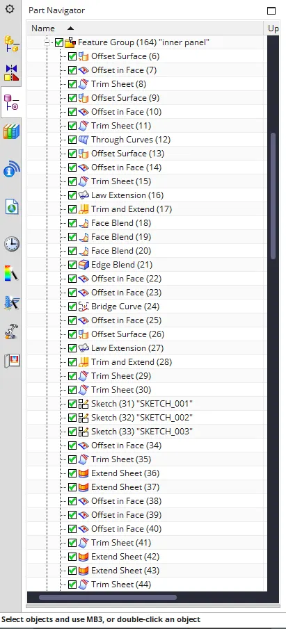
The below images show all the tools used for creating the box assembly model.
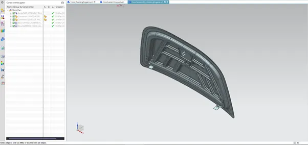
Hood assembly views:
Front view
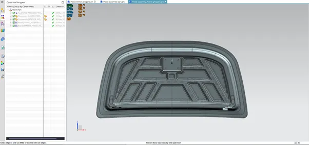
Top view
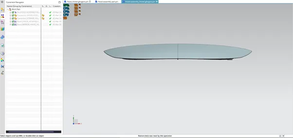
Bottom view
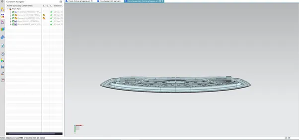
Side view
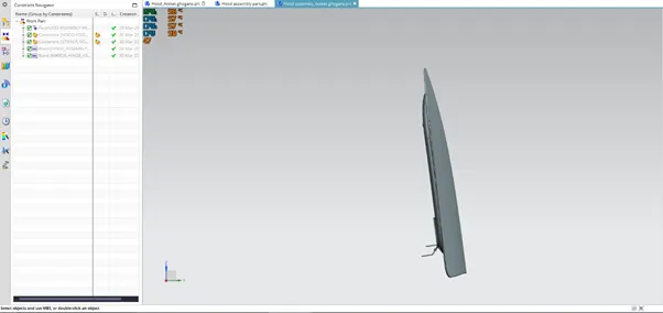
Isometric view
Conclusion:
Thus after following the steps of design methodology and using the tools mentioned above, the assembly of the hood design is complete.