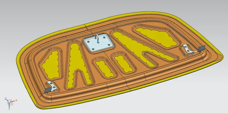
Hood design-Week 2
CREATION AND EXECUTION OF DESIGN BY USING MASTER SECTION
(HOOD DESIGN WITH ENGINEERING FEATURES)
OBJECTIVE:
The main objective is to create a Hood design using Siemens NX 12. The design of Hood includes HOOD IMMER PANEL, OUTER PANEL, LATCH, HINGE and REINFORCEMENT. Combination of these includes the asssembly of HOOD.
MASTER SETION:
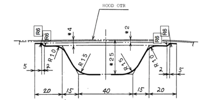
STEPS TO BE FOLLOWED ARE;
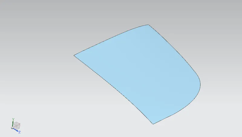
STEP 01 – INSERT THE OUTER PANEL
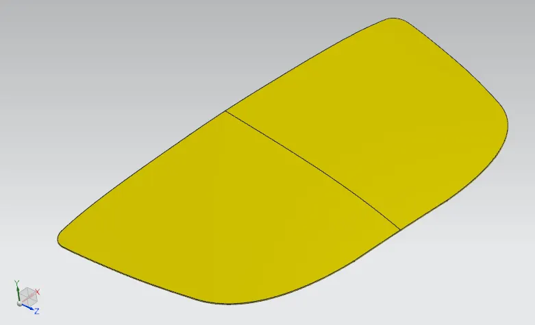
Insert a basic component like no thickness element into NX 12 and name it as OUTER PANEL and check for the boundary condition. The boundary condition is used to identify the continuity of the component.
STEP 02 – WORKING SURFACE CREATION (INNER PANEL)
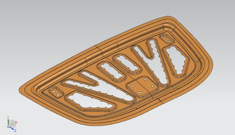
After this panel outer surface insert make the copy of the face by using ofset section and start the outer panel development with the help of master section.
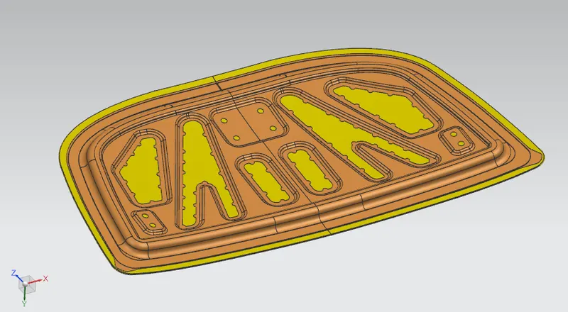
Develop the outer surface with ofset and trim comment. Then make the EMBOSS option and the proper profile creation as mentioned in the master section.
These steps are followed for only half section and make sure that the mirror face is correct postion.
Now make the sketch and cut the embossed area are not required and as well as the Mastic profile creation.
After this make the second half of inner pannael by using mirror geomtery option and finally go for the sew option to make the two featires into a single format.
STEP 03 – WORKING SURFACE CREATION (OUTER PANEL)
Now show the outer surface and offset with the value needed and make the surface as a working surface.
STEP 04 – HEMING AREA CREATION
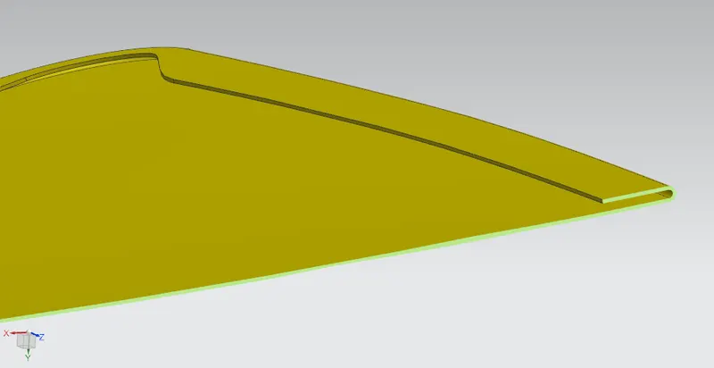
Offest the outer edge of the surface to 15 mm and make sure that the interference is not there. Now make the law of extension option and go for the needed value. Finally make the curve surface by using face fillet option to create a heming curve profile. create a second half by using mirror symmetry option and sew the two face into single.
STEP 05 – SURFACE TO SOLID CREATION
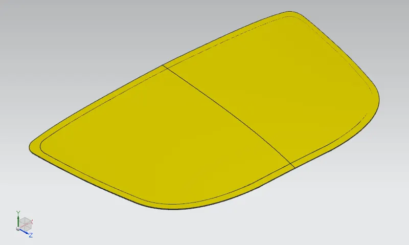
By using the thicken option use the sew profile into thick solid upto 0.75mm. Same option will go for Inner panel.
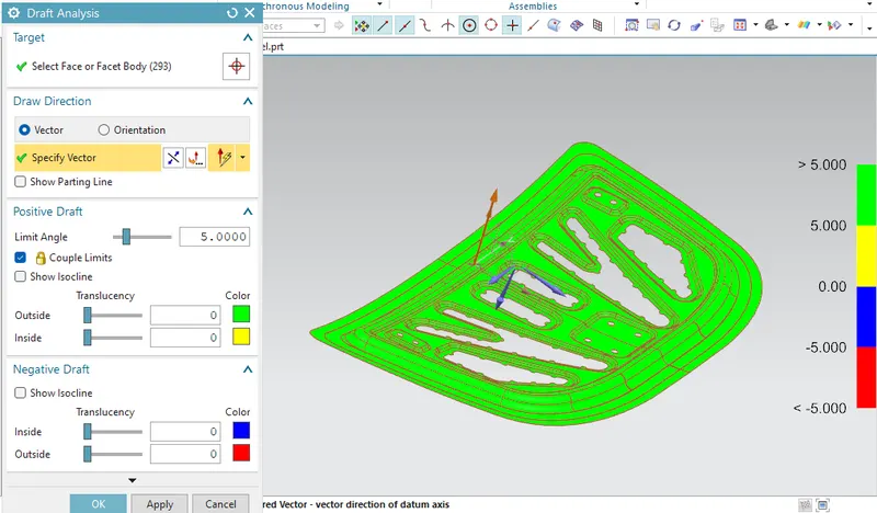
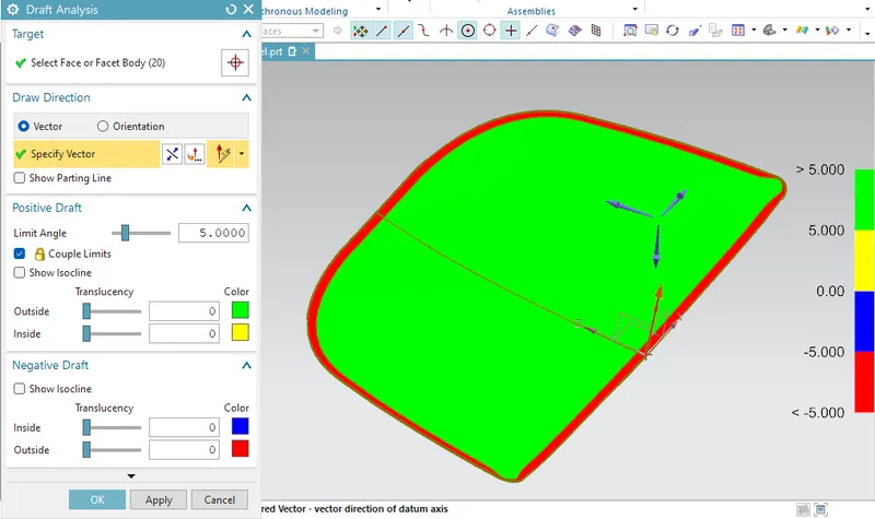
STEP 06 – DRAFT ANALYSIS
finally go for the Draft analysis option to each surface and solid profile for both Inner and Outer panel.
STEP 07 – ASSEMBLY CREATION
By using assembly tool insert the each solid part and make the assembly. for both inner and outer panel needs only FIX constrain. for hinge and striker use the touch and ditance constrain to fix them.