Hood design-Week 2
DESIGNING A CAR HOOD – BIW INNER PANEL AND OUTER PANEL BY FOLLOWING EURO NCAP STANDARDS
OBJECTIVE
The main objective of this project is to design the Hood of a car that satisfies the manufacturing requirements, functional requirements, and as well as Euro NCAP standards. The Body in white (BIW) inner panel and outer panel of the hood must be designed and assembled with the Hinge Assembly, Latch and Striker with their reinforcements.
INTRODUCTION
A car hood, also referred to as a bonnet in some other countries, is the hinged cover that rests over the engine of a front-engine vehicle. Its purpose is to provide access to the engine for repair and maintenance. A concealed latch is typically used to hold down the hood. On vehicles with an aftermarket hood and on racecars, hood pins may be used to hold down the car hood. Hoods sometimes also contain a hood scoop, wiper jets, power bulge, and/or hood ornament. Car hoods are typically constructed from steel and sometimes from aluminum. Aftermarket car hoods may be constructed from various other materials, including carbon fiber, fiberglass, or dry carbon.
Concerns regarding the severity of a potential pedestrian head injury during a collision with a motor vehicle have led to advanced hood designs on many models. Such designs may include a multi-cone inner hood panel design. An active structure that is capable of pushing the surface of the hood away from the vehicle's hard motor components in the event of a pedestrian crash is also in use. Pyrotechnic or spring force designs are often used in active-hood design.
Body in white is the stage in automobile manufacturing in which a car body's frame has been joined together, that is before painting and before the motor, chassis sub-assemblies, or trim have been integrated into the structure. Assembly involves different techniques such as welding (spot, MIG/MAG), riveting, clinching, bonding and laser brazing.
The term derives from manufacturing practices before steel unibody monocoques when automobile bodies were made by outside firms on a separate chassis with an engine, suspension, and fenders attached. The manufacturers built or purchased wooden bodies (with thin, non-structural metal sheets on the outside) to bolt onto the frame. The bodies were painted white prior to the final color.
DESIGNING THE HOOD:
Software used: NX CAD
Manufacturing Requirements:
Minimum fillet radius = 3mm+Thickness
No sharp corners inside the component
No curvatures lesser than 5mm
Small embosses should not exceed the maximum depth of 6mm (staying on the safe side)
Mounting areas and welding areas need to be flat
Provide appropriate corner relief on the area of curvature.
Provide exact mastic points to reduce the NVH.
Data to be used:
Master sketch
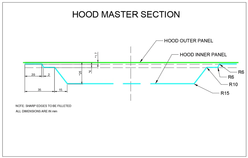
The master section is created based on the requirements received from the marketability team and the manufacturing requirements that we saw before. Below are the images of the master section used for the design.
Hood Thickness Information:
Outer Panel Thickness = 0.75mm
Inner Panel Thickness = 0.75mm
Reinforcement Thickness = 1.5mm
DESIGN APPROACH
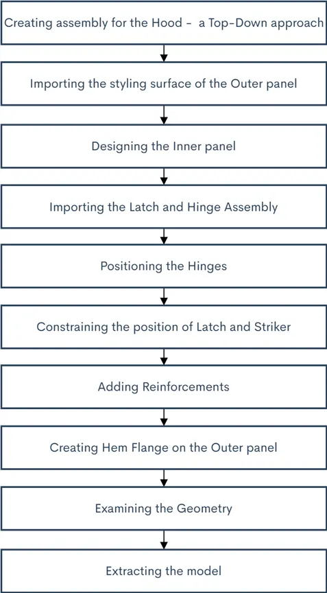
TOP-DOWN APPROACH
With top-down approach users start to design a product by defining but not detailing its first-level components. Each component is then refined in more details by defining its sub-components. The process is continued till all low-level components are defined and detailed.
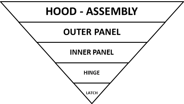
In this project the top down approach was used because the styling surface and reinforcements were already designed. Hence by creating the assembly then the hood inner panel was designed and the embosses for positioning the hinge assembly, latch and striker were created.
A SHORT STUDY ABOUT THE WAD:
During most pedestrian-vehicle crashes the car front impacts the pedestrian and the whole body wraps around the front shape of the car. This influences the head impact on the vehicle. Meanwhile the windscreen is a major impact point and tested in NCAP conditions. The severity of injuries is influenced by car impact speed; type of vehicle; stiffness and shape of the vehicle; nature of the front (such as the bumper height, bonnet height and length, windscreen frame); age and body height of the pedestrian; and standing position of the pedestrian relative to the vehicle front. The so called Wrap Around Distance WAD is one of the important measurements for the assessment of protection of pedestrians and of bicyclists as well because the kinematic of bicyclists is similar to that of pedestrians.
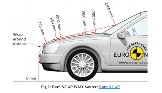
For this study accidents of GIDAS were used to identify the importance of WAD for the resulting head injury severity of pedestrians and bicyclists. GIDAS (German In-Depth-Accident-Study) collects accidents as representative sample of the German accident situation based on in-depth-investigation. A total number of n=548 pedestrian and n=436 bicyclists suffered a head impact with the car collected within n=27,666 accidents with all kind of traffic participants and injured persons from the years 1999 to 2013 which are used for the study.
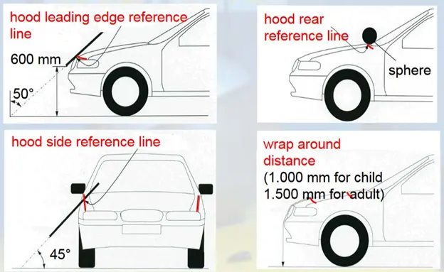
Results: A significant influence respectively an increase of WAD by the driving speed of the bicycle cannot be found. The cumulative frequencies show, that WAD 1500 only covers about 8% of bicyclists but 18% of pedestrians. WAD 2100 covers about 51% of bicyclists and 74% of pedestrians. The WAD for pedestrian as measure of distance from the ground to the impact point of the head is dependent on the impact speed of the car. For lower speeds the front hood area is more often contacted and for higher speeds the windscreen. For Vans and off-road cars front hood impacts can only be seen in lower speed collisions. The WAD of bicyclists in general is higher than for pedestrians. The cumulative frequencies of body heights show that bicyclists are larger than pedestrians. The injury severity of the head (AIS head) is increasing with the age of the pedestrian or bicyclist. Only 6.9% of pedestrians and 3.3% of bicyclists in the age group of 16 to 25 years suffer head injuries of AIS 3+, in the age group over 55 years there are 19.7% of pedestrians and 16.1% of bicyclists.
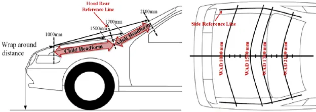
The WAD is not a significant influence parameter for the injury severity of the head. The WAD is only increasing slightly with higher injury severity of the head (AIS head). The WAD is a usable parameter for the correlating impact speed of the car. Age and impact speed of the car have highly significant influence (p<0.001) and body height has slightly significant influence on the injury severity of the head (p<0.05).
HOOD ASSEMBLY
- First the neutral data file of the styling surface was extracted.
- Then by keeping it as a parent file two work surface was created and named separately as hood inner panel and outer panel.
- Then in assembly navigator a new assembly was created and the parts and sub-assemblies were added into it.
- After creating the inner panel and outer panel the hinge assembly and latch will be constrained.
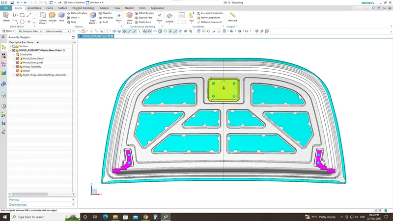
HOOD INNER PANEL
- By using the wave geometry linker the styling surface will be extracted as a linked body.
- The styling surface was trimmed into half using the trim surface along x co-ordinate.
- Then two surfaces at the offset of 0mm were generated and one feature grouped as parent file and the other one was used as the working surface.
- By using the master sketch three surfaces were off-set at a distance of 2mm, 4mm and 25mm downwards.
- For creating the 5mm flange the corner of the tangent curve will be offset inwards at the distance of 20mm with a 30mm filleted corner and the remaining portion was trimmed.
- Then for creating the next flange the second offset surface was trimmed at a distance of 40mm.
- By using through curves both the surface were connected to create a flange at an outward angle of 80 degree as per the manufacturing parameter.
- Then the third surface was trimmed and used to create the flange at the distance of 55mm.
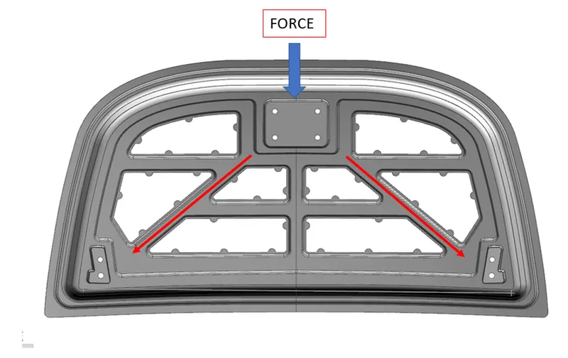
- Then the required embosses were created to reduce the transmission of force and it should satisfy the requirements of NASC regulations and the embosses must have a outward draft to satisfy the tooling direction.
- Below diagram represents the ideology of the design, the orange line represents the direction of force dissipation when the hood attempts an unexpected crash.
- Then by using the edge blend and face blend all the sharp corners were blended and smoothened out as per manufacture requirements.
- For fixing the hinge assembly a flat surfaced embosses were created which is exactly parallel to the x coordinate.
- Then to avoid the intersections while mirroring the intersecting curve was extended and trimmed exactly then the other half was mirrored and sewed together.
- Now the latch emboss was created using the linked surface of the latch and for creating the emboss trim and extend were used following the Law extension.
- Finally the inner panel was created successfully by thickening it to 0.75 mm.
MASTIC SEALANT :
The Mastic sealant or the Mastic point is an elastic compound that behaves like a rubber. The mastic points are defined on the hood inner panel where the hood can easily deform. They help the hood outer panel to come back to its original shape after it gets deformed. The mastic has an influence area of 80mm. The circle in yellow dotted line is the influence area by mastics.
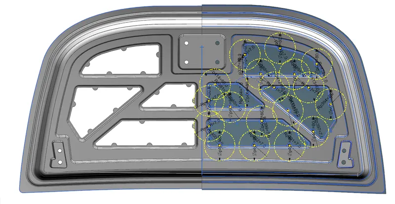
While creating the emboss a coin shaped extends were created for applying the mastic points. The mastic points will help the inner panel fixed with the outer panel.
But the main function of the mastic point was to reduce the NVH (Noise, Vibrations and Harshness) created on the hood. The mastic point will reduce the NVH for the radius of 80mm. So providing many number of mastic point on the center area of the hood will increase the performance of the car.
HOOD OUTER PANEL
Hemming Data :
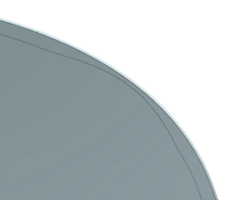
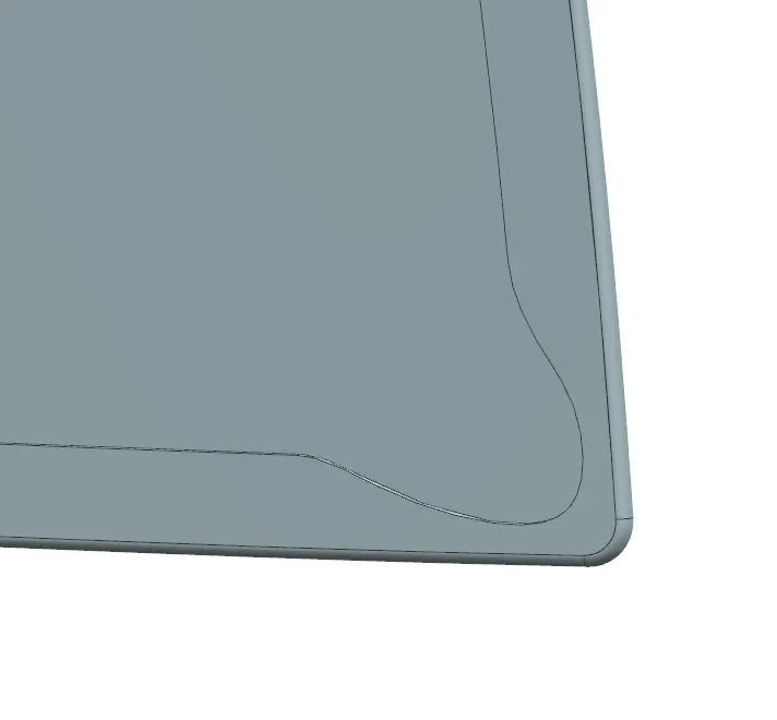
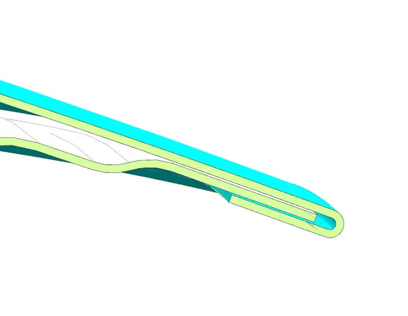
Hemming is the process of joining both the outer and inner panels together. The hemming process roles and wraps the hood outer panel around the inner panel and holds it tightly together. The following are the dimensions followed for hemming.
Front relief:
Relief rear section:
- The hood outer panel was created by creating an offset surface from the styling surface and then trimmed into half.
- Then for creating the Hem flange about 6mm around the outer panel for creating the hold with the inner panel.
- Then law extensions were used on the outside curve and the generated surface was offset to 6mm and then the remaining portions were trimmed.
- By using the Face blend the hem flange were created.
- By using the curve on surface and trim sheet the required corner relief was provided on the top and bottom corner as requirement.
- Now the other half was mirrored and sewed together.
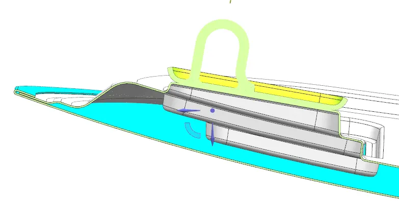
- Below figures will show the section view of the hood assembly which explains the tolerance, smoothness, and face intersections were achieved as per the manufacturing requirements.
POSITIONING THE HINGE ASSEMBLY
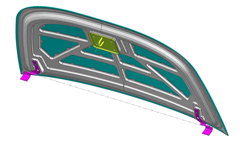
- The hinge assembly were positioned by applying the required constraints.
- First the inner panel was fixed and then a line was created horizontally connecting the hinges and then the hinges were constrained with a parallel mate.
- The back surface on the hinge hood part was touch/allign with the top surface of the hinge emboss on the inner panel.
POSITIONING THE LATCH AND STRIKER
- First the latch was positioned roughly using the constraints and by exporting the back surface of the latch using wave geometry linker.
- Then by using the linked surface the emboss for the latch was created but before doing that the linked surface must be extended all around for creating a clearance for the edge blends.
- Now the required circle from the center point of the hinge axis was created and a line tangent to the circle and a line vertical to the striker point from the latch were created.
- Now both the lines were aligned together and then the latch will have its perfect position for striking with the engine compartment.
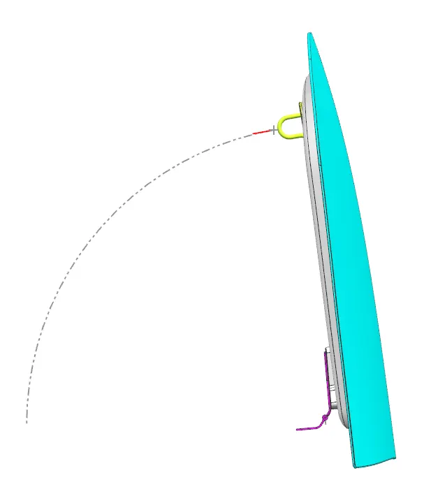
- The red line from the above figure represents the vertical line created from the latch and the grey dotted line was the tangent line of the circle.
- Now if we move the hood as closing then the striker will meet the exact location of the striker point in the engine compartment.
CONCLUSION
Finally the Body in white Hood of a car was designed as per the industrial manufacturing requirements following the Euro NCAP standards.
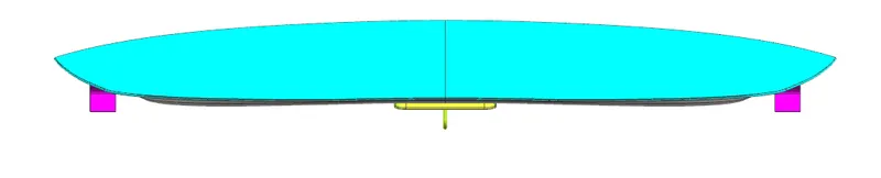
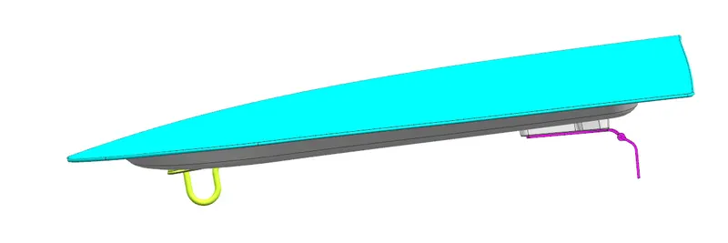
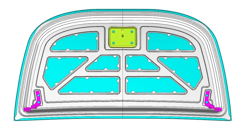
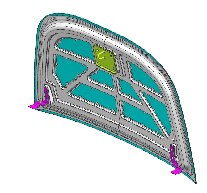
PHOTOS OF THE HOOD IN FINAL ASSEMBLY: