Hood design-Week 2
Hi,
Here I am submitting the Hood design of Inner Panel, Outer Panel & other reinforcements.
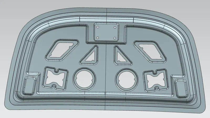
Procedure followed for Hood Inner panel design:
- Initially, started the hood inner panel by using Hood skin data by offsetting the surface to 1.7mm.
- Then trimmed half the sheet using ‘trim body’.
- Then saved it in a feature group called ‘working surface’.
- And offsetted the working surface to 0mm using ‘offset surface’.
- Using ‘offset in face’ to 25mm & trimmed the inner sheet using ’trim sheet’.
- And offsetted the working surface to 4mm using ‘offset surface’.
- Using ‘offset in face’ to 40mm & trimmed the outer sheet using ’trim sheet’.
- Then using ‘through curves’ connected both the sheets.
- And again, offsetted the working surface to 18mm using ‘offset surface’.
- Using ‘offset in face’ to 55mm & trimmed the outer sheet using ’trim sheet’.
- Using ‘law extension’ extended the edges.
- Then trimmed the extra faces using ‘trim and extend’.
- Finally blended the surfaces using ‘face blend’ & ‘edge blend’.
- Then created a plane tangential offset to 10mm & created an emboss there for striker & hinge mount space.
- And blended the edges using blend tools.
- Then created the emboss sketches on the ZC plane & projected it on the surface for dissipating the force radially.
- Then created the cutouts in between the embosses for reinforcements.
- And created mastic points on the curvatures.
- Then created the emboss for the hinge mounting parallel to the yc plane by placing hinge on the location.
- Finally, mirrored the the sheet to the opposite side.
- After completing the striker emboss, I sewed the sheets & thicken it to 0.75mm.
Procedure followed for Hood Outer panel design:
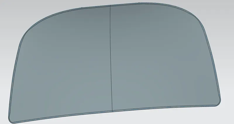
- First, I have trimmed the body as same in inner panel.
- Then, offsetted the outer edge of the sheet to 0.5mm & trimmed it using ‘trim sheet’.
- Then used ‘law extension’ on the edges & offsetted the surface to 7mm.
- And offsetted the outer panel body to 2.65mm.
- Using ‘trim sheet’ trimmed the extra flanges, which was doing by the hemming process.
- And for the hemming corner reliefs, drawn the curve on the face of the hem & using ‘trim sheet’ trimmed the external faces.
- Finally, mirrored the body to the other side, sewed them & thicken it to 0.75mm.
Procedure followed for Hinge assembly:
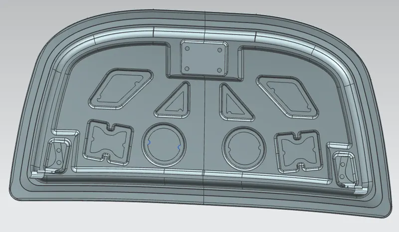
- Initially, inserted the hinge assembled part into the assembly.
- Then moved approximately to the place of hinge emboss created on the inner panel.
- And given the assembly constrains to both by giving parallel constrain to the hinge axis & the x-axis of the assembly.
- Then given touch constrain to the back face of the hinge hood part & to the emboss.
- Thus, hinge gets constrained to the inner panel.
- And then mirrored the hinge assembly to the other side using ‘mirror assembly’ & made associative.
- And saved the mirrored assembly as separate part.
- Finally, on the hood assembly, drawn the points on the both hinge axes, drawn a line by joins both to find the axis of the hinges is collinear.
Procedure followed for Striker assembly:
- Initially created a trajectory circle on the hinge axis using yc plane of diameter 632.
- And drawn an angular line from the axis of 82 degress from x axis.
- Then drawn a tangential line on the curve from the angled line end point.
- Then inserted the striker into the assembly & drawn a line on the latch perpendicular to the face.
- Then given constrains to the striker by touch to the back face of the striker to the emboss created on the inner panel.
- And given parallel constrain to the line drawn on the striker to the yc plane.
- And given touch constrain to the line drawn on the striker to the trajectory tangential line.
- Finally, assembled the striker to the inner panel.
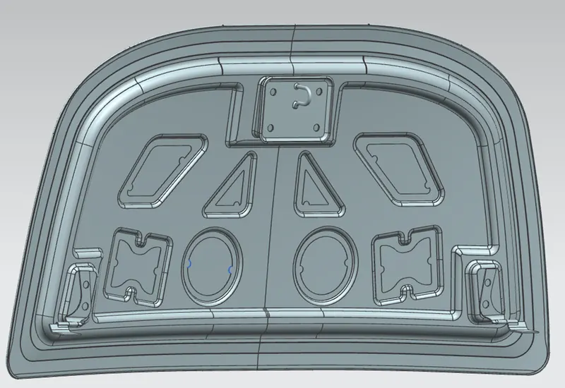
Finally, submitted the hood inner panel, outer panel, hinge & striker on the hood assembly.
Thanks,
Deepak kumar A S.