Gate Valve Parametric Study
Problem Definition
We have to perform a parametric study on the gate valve simulation by setting the opening from 10 % to 80%.
Obtain the mass flow rates at the outlet for each design point.
Calculate the flow coefficient and flow factor for each opening and plot the graph.
Discuss the results of the mass flow rate and flow coefficient.
Introduction
Parametric Study
Parametric studies allow us to nominate parameters for evaluation, define the parameter range, specify the design constraints, and analyze the results of each parameter variation. So in the parametric study when we are going to define parametric input, fluent is going to change the parameters according to input and we get the answer according to the input. We just have to nominate that parameter for the parametric study input and fluent is going to solve the problem according to that.
Gate Valve
Gate valves are used to shut off the flow of fluid by inserting a rectangular gate or wedge into the path of a flowing fluid. Gate valves require very little space along the pipe axis and hardly restrict the flow of fluid when the gate is fully opened enabling gate valves to offer straightway flow with very little pressure drop. Gate valves are mostly used with larger pipe diameters (from 2″ to the largest pipelines) since they are less complex to construct than other types of valves in large sizes.
Flow coefficient
When flow goes through a valve or any other restricting device it loses some energy. The flow coefficient of a device is a relative measure of its efficiency at allowing fluid flow. The flow coefficient is a designing factor that relates head drop (Δh) or pressure drop (ΔP) across the valve with the flow rate (Q).
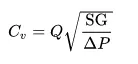
Mathematically the flow coefficient Cv (or flow-capacity rating of the valve) can be expressed as
where
ΔP = Pressure Drop (expressed in psi)
SG = Specific gravity (1 for water)
Flow Factor
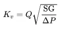
The metric equivalent flow factor is calculated using metric units (`m^3*h^-1*"bar"^-0.5`)
where
`K_v` = Flow Factor (`m^3*h^-1*"bar"^-0.5`)
Q = Flow rate (`m^3`/h)
SG = Specific gravity (1 for water)
ΔP = Pressure Drop (expressed in bar)
Relation between Flow Factor and Flow Coefficient
`K_v = 0.865*C_v`
Case Setup
1. First we are going to open the workbench and going to click on Fluid Flow(Fluent). It is going to open the module in the Project Schematic.
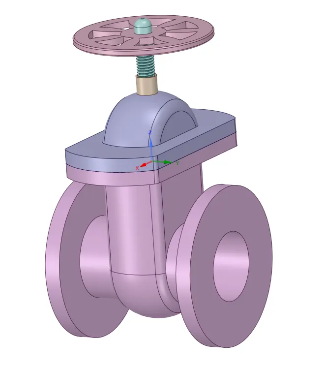
2. Now we are going to click on the geometry. It will take you to the SpaceClaim. Here we are going to open the existing design. So now we can see the original design.
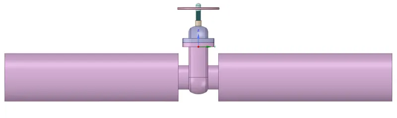
3. Now we want to extend the fluid flow regions at the inlet and outlet so we are going to use the pull option and we are going to extend them to 800 mm.
4. Now we are going to pull the gate disk by 10 mm and we are going to do the parametric study so we are going to select the parametric option.
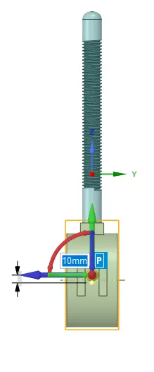
5. We only want the fluid volume so we are going to extract the fluid volume. In order to do that we will go to the prepare, then we are going to select the volume extract option. We are going to select the edges of the fluid body and we are going to extract the fluid volume. Now we are going to update the volume body. We are going to suppress the solid body for physics.

6. Now we are going to open the mesh. We are going to give the element size to be 8 mm.

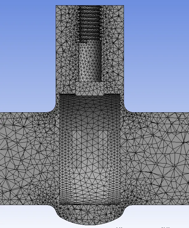
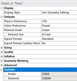
Now we are going to give the name inlet and outlet. Now we are going to update the mesh.

7. Now we are going to Setup the case. We are going to select our model to be k-`epsilon` Realizable with Scalable wall Function.
8. In the Fluent we will go to Physics. Here we choose the type of solver, we have taken the pressure-based type solver. The Mach number value is less than 0.33 that's why we are using pressure-based solver.
9. Now we have to choose the velocity formulation, we have taken absolute velocity formulation. Now we are going to choose the time, we are using a steady time. We are going to enable gravity. So we are going to give the -9.81 m/`s^2` in the z-direction.
10. Here we are use water as fluid. So we go to the material and we are going to copy the material from the fluent database. So, in this case, we are using water. We are going to delete the air from the materials.
11. Now we are going to give the boundary condition. We are going to take the pressure inlet and pressure outlet boundary condition. We are going to take 10-pascal pressure at the inlet and 0 at the outlet.
12. Now we are going to create the definition to calculate the mass flow rate at the outlet and we are going to enable the option of creating output parameter. We are going to initialize the case setup and start the calculation.
13. After the calculation we are going to click on the parameters to calculate the mass flow rate at the different-different lift length. Now we are going to update all design points.
Result
Residual
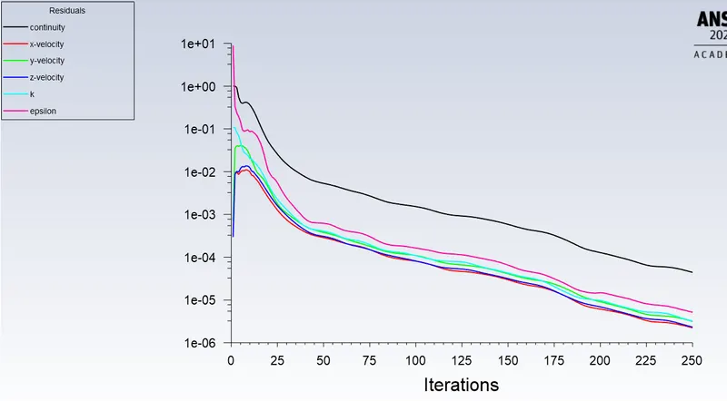
From the residual graph, we can see that the graph that the values we are getting are very low. So we can say that we get the converged result.
Mass Flow Rate at Outlet
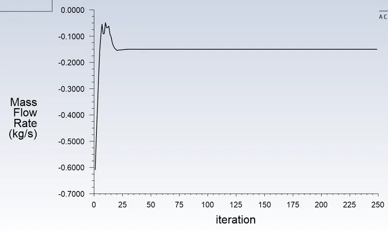
We are getting the mass flow rate in negative. Because mass is going out from the system.
Velocity plot
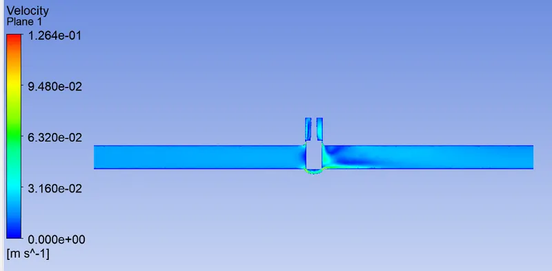
In the above plot, we can see the velocity distribution in the gate valve. Velocity is high just after the valve gate. We get the maximum velocity to be 0.126 m/s.
Pressure plot
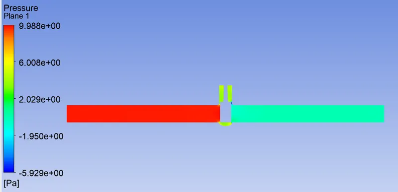
In the above plot, we can see the pressure distribution in the gate valve. It is maximum at the inlet. We have given the inlet pressure to be 10 pascals.
Velocity Vector
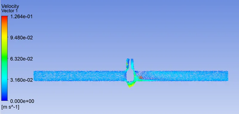
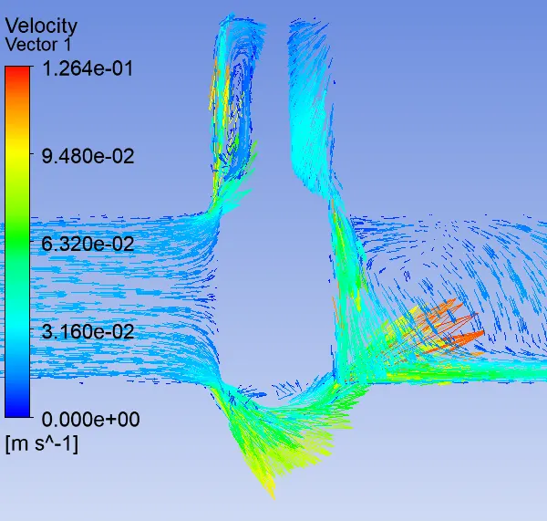
This is the velocity vector plot. We can see the velocity with their direction at every point of the gate valve.
Flow Coefficient
For case-1
`C_v = Q*root"((SG)/(triangleP)`
`C_v = 0.14998/998*3600*root"(1/0.0001)`
`C_v = 54.1010` GPM/PSI
Flow Factor
`K_v = 0.865*C_v`
`K_v = 0.865*54.101`
`K_v =`46.7973`m^3*h^-1*"bar"^-0.5`
We are going to take the same procedure to calculate flow factor and flow coefficient for the other cases.
Comparision
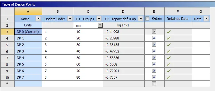
| Case | Lift | Mass flow rate | Flow Coefficient (in GPM/PSI) | Flow Factor (`m^3*h^-1*"bar"^-0.5`) |
| 1 | 10 | 0.14998 | 54.1010 | 46.7973 |
| 2 | 20 | 0.23988 | 86.5298 | 74.8483 |
| 3 | 30 | 0.36155 | 130.4188 | 112.8123 |
| 4 | 40 | 0.47732 | 172.1795 | 148.9353 |
| 5 | 50 | 0.56356 | 203.2881 | 175.8443 |
| 6 | 60 | 0.6668 | 240.5290 | 208.0576 |
| 7 | 70 | 0.72201 | 260.4444 | 225.2844 |
| 8 | 80 | 0.7857 | 283.4188 | 245.1573 |
Effect of the lift value on the mass flow rate
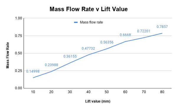
The mass flow rate of the fluid increases when we increase the lift value. Because when the gate valve lifts fluid gets more space to go through so the mass of the water increases which passes through the valve and as a result mass flow rate increases.
Effect of the lift value on the flow coefficient and flow factor
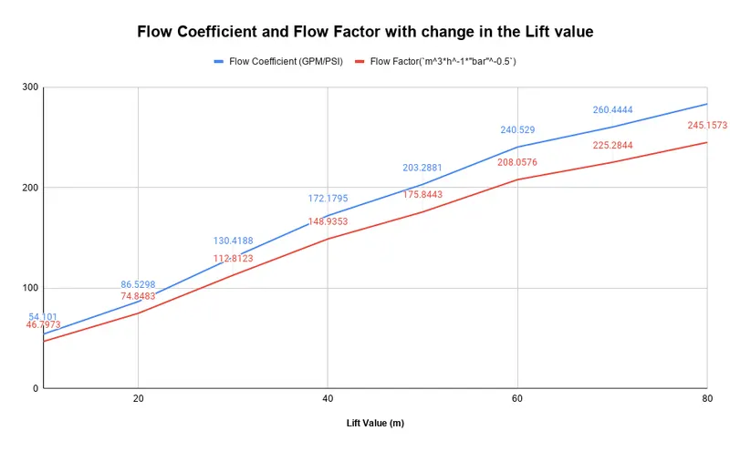
With the increase in the lift value both flow factor and flow coefficient increase. Because lift value increases the mass flow rate of the water increases and they are proportional to the mass flow rate.
Conclusion
Mass flow rate is increasing with the increase in the lift value, mass flow rate increases.
With the increase in the lift value, the flow factor value increases. Because it depends on the mass flow rate.
With the increase in the lift value, the flow coefficient value increases. Because it depends on the mass flow rate.