Front View Geometry and Roll Center Height 1
Aim: This challenge tests your understanding of roll center construction. Do these calculations manually (not using a suspension tool like Adams or MotionSolve) to enhance your understanding
It is advisable to do this exercise in an excel sheet so that you can change hardpoints and study the effects
Also, draw a rough sketch using the hardpoints to visualize the suspension. Remember this is purely a 2D setup (front view) for the left wheel
1.Calculate the following geometric parameters:
i.Instant center location (coordinates)
ii.Roll center height
Assume the tire radius to be 300 mm and the track to be 1600 mm
Assume the setup to consist of links rather than control arms
Coordinate system
X – not needed (only the yz plane is relevant here)
Y – pointing towards the right
Z – pointing towards the top
Answer: we have ploted all the points i.e point (105,425) and (285,460) ,makes the upper upper link and point (105,185) and (370,170) makes lower link.
Now to find I center we need to extend the two links and joining point will be the I center.
For roll center we join line from I center to the center axis of the vehicle passing through the tyre Ground contact of the vehicle.As shown is the figure below:
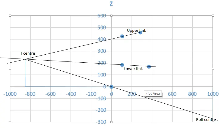
Ploting the graph we got the locatiom of the I centre and the roll centre. Now we Start to calculate the Coordinates of I centre and Roll center.
In X axis for 200 units it covers a distance of 1.16cm And in Y axis for 100 units it covers a distance of 0.67cm.
Now we claculate the distance of I centre.
In X axis: The distance covered is 4.85cm and on converting we get 837 in negative axis.
In Y axis: The distance covered is 1.52cm and on converting we get 227 in positive axis.
So the coordinate of I centre: (-837,227)
Now we claculate the distance of roll centre.
In X axis: we Know that it cuts on 800 in positive axis.
In Y axis: The distance covered is 1.43cm and on converting we get 214 in negative axis.
So the coordinate of Roll centre: (800,-214)