Frame Floor and Tunnel Challenge
-:FRAME FLOOR AND TUNNEL ASSEMBLY:-
OBJECTIVE:
Design and develop the frame, floor, and tunnel assemply for an SUV using NX CAD. Design individual components and attach them to the rest of the Frame structure and these parts to be welded together.
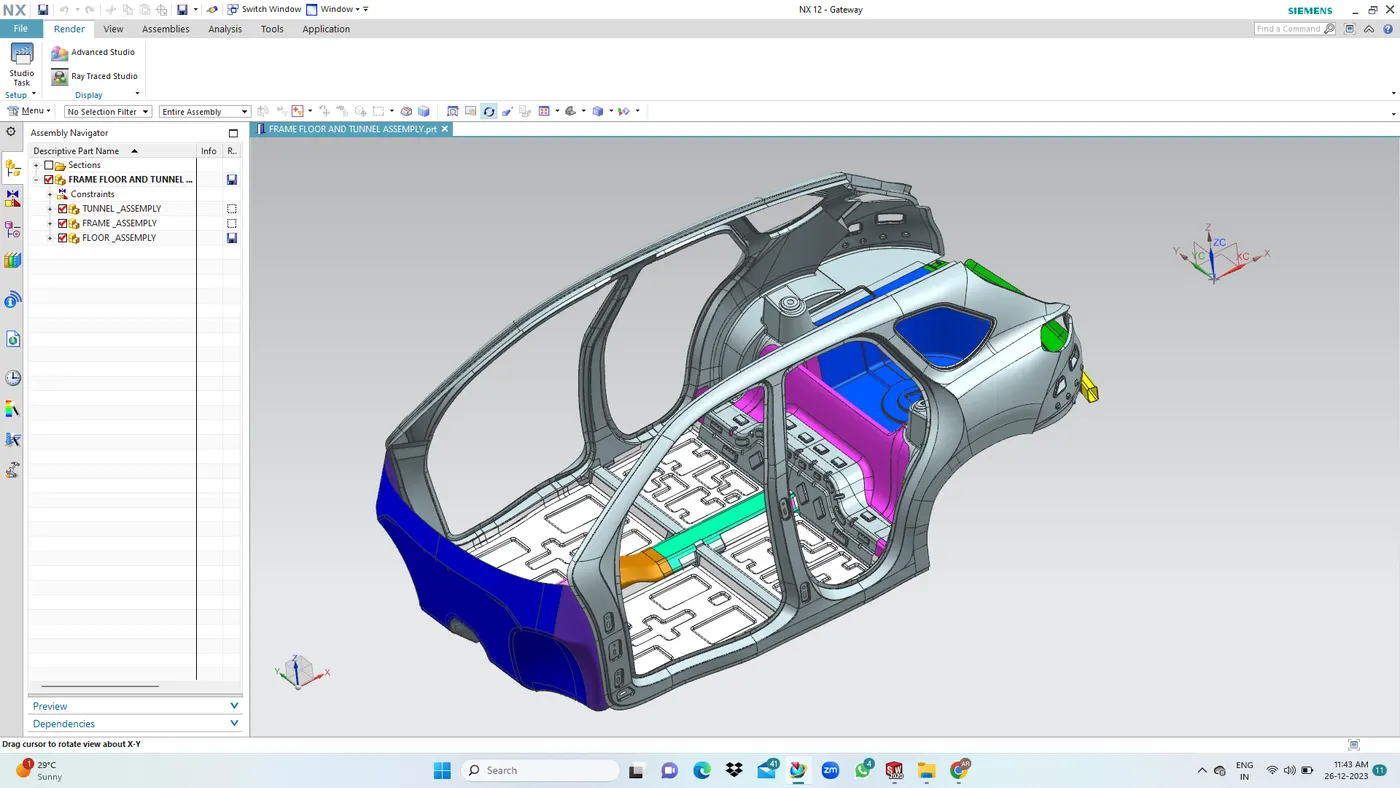
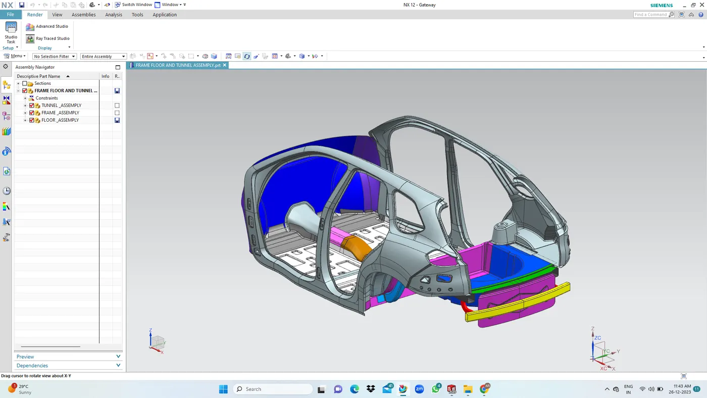
FLOOR ASSEMBLY:
There are tow types of assemply inthe frame floors.
1. Front Floor Assembly
2.Rear Floor Assembly
FRONT FRAME FLOOR ASSEMBLY:
These components are the support structure of the front and rear seats of the car and are responsible for taking the load of the passengers. Some of the components integrated with the front floor assembly are Side-Body inner panel, Tunnel assembly, Frame assembly, Dash panel etc.
1. Front Floor LH & RH: In case of the side impact the embosses on the floor are given in such a way that the force gets adviated and travels throughout the surface and the load from the side impact get distributed, rather than accumulating in one direction which can increase the damage to passenger. Similar distribution of the force can be observed in case of the frontal impact as wall.
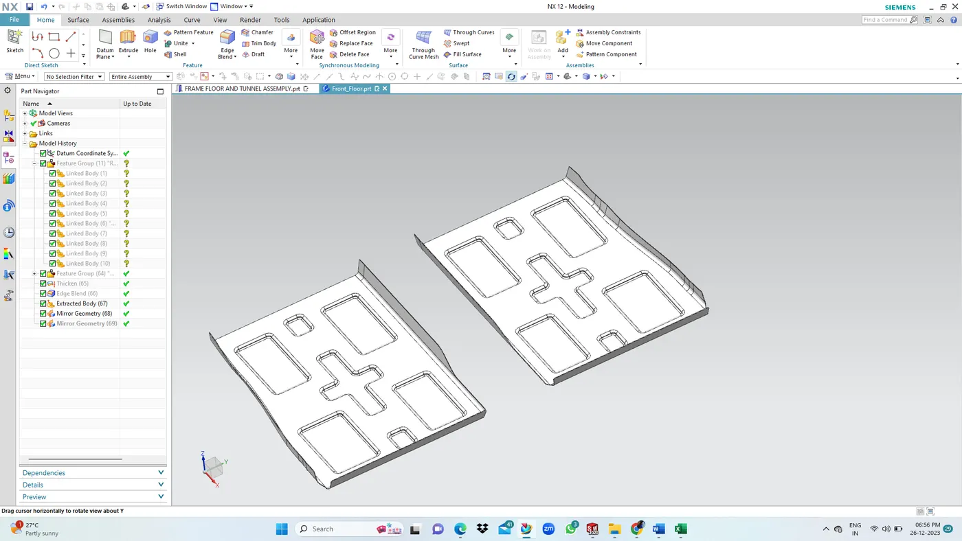
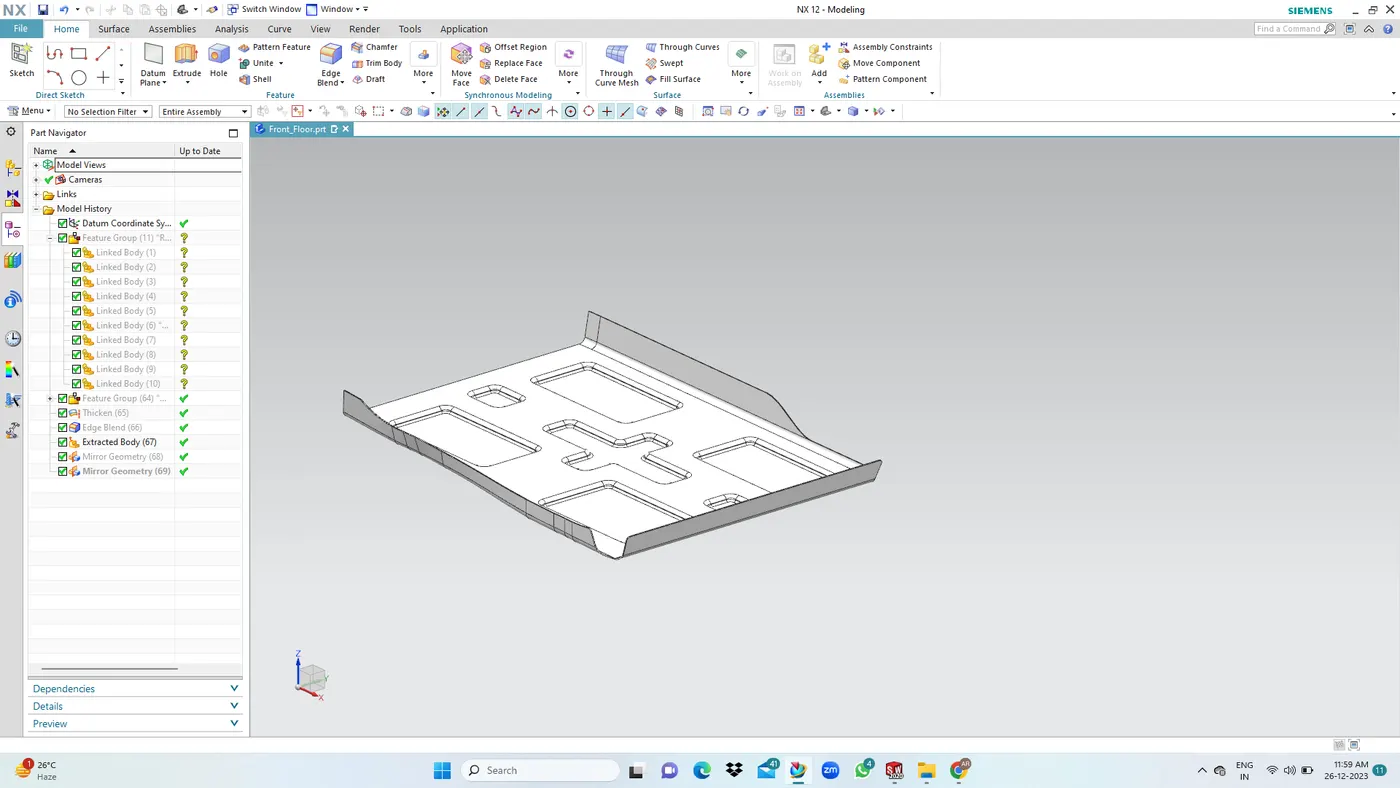
2. Middle Floor LH & RH: In case of the side impact the embosses on the floor are given in such a way that the force gets adviated and travels throughout the surface and the load from the side impact get distributed, rather than accumulating in one direction which can increase the damage to passenger. Similar distribution of the force can be observed in case of the frontal impact as frame.
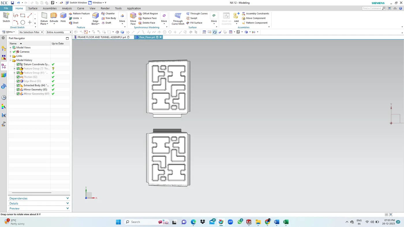
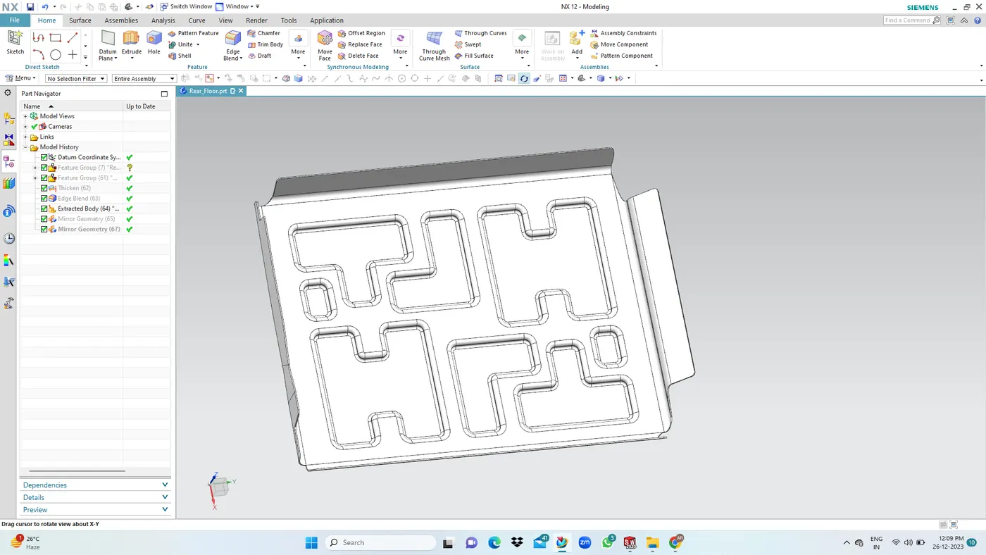
3. Reinforcements LH & RH: Conventionally reinforcements that connect right and left-side front of A-Piller and dash panel, so reduce damage to a vehicle body.
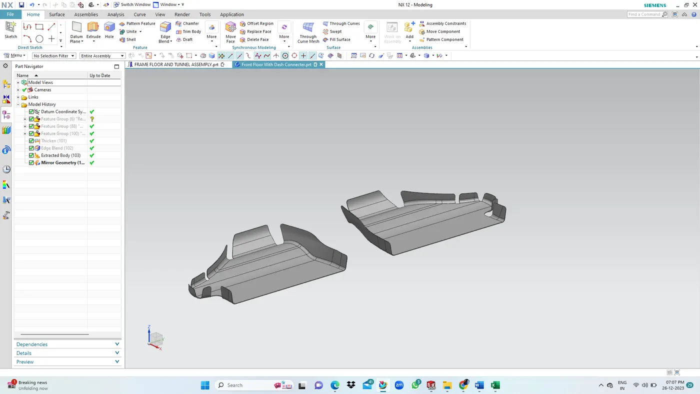
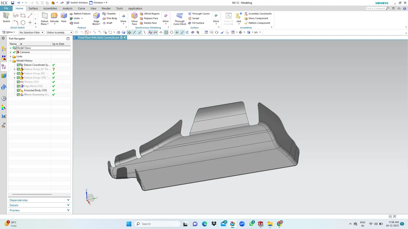
Front Floor And Side Body Inner Panel Integration: Preferrred method - Spot welding
Spot welds are applied at multiple places along the joining flanges of both parts. Sheet metal requirements for sopt weld.
- Optimum material thickness range 05-4mm.
- Minimum clearance for the weld gun to perform the action - 15mm.
REAR FLOOR ASSEMBLY:
These components are the structure of the rear seat and rear bumber of the car and are responsible for taking the load of the luggage area. Some of the components integrated with the rear floor assembly are side-body inner and frame assembly..
1. Spare Wheel Panel: A spare wheel part are mounted below the cargo area and between the raer main frame. we are providing the embosses for aditional strength of the panel.
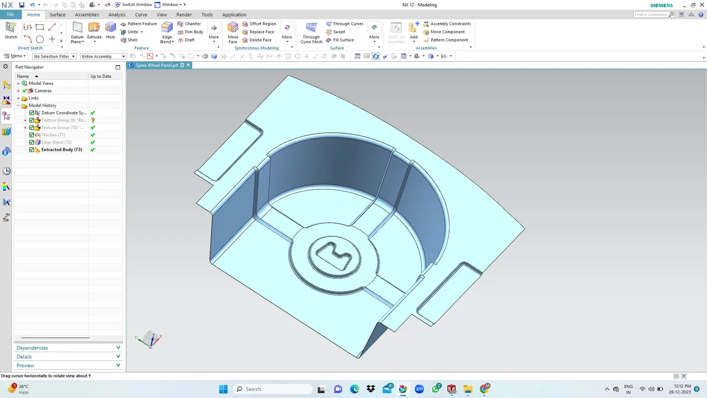
2. Rear Connecting Panel: Its a incorporation for the spare wheel portion.
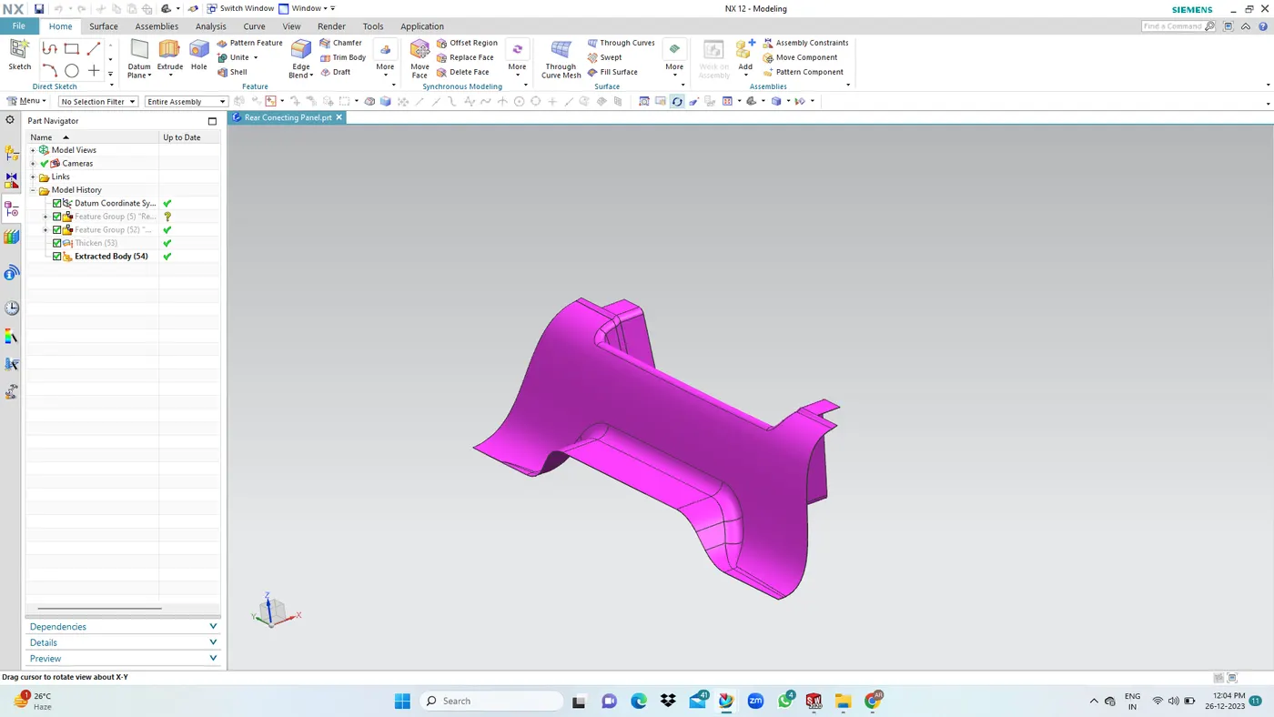
3. Rear Floor & Rear Connecting Panel:In this part connected to the rear connecting panel and middle floor region.
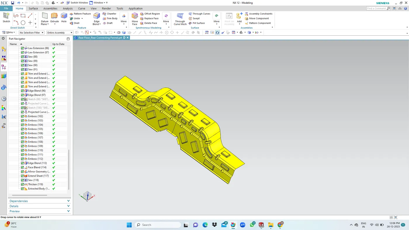
4. Rear Body: Rearmost panel of the car, and we are providing the embosses for aditional strengthening of rear impact.
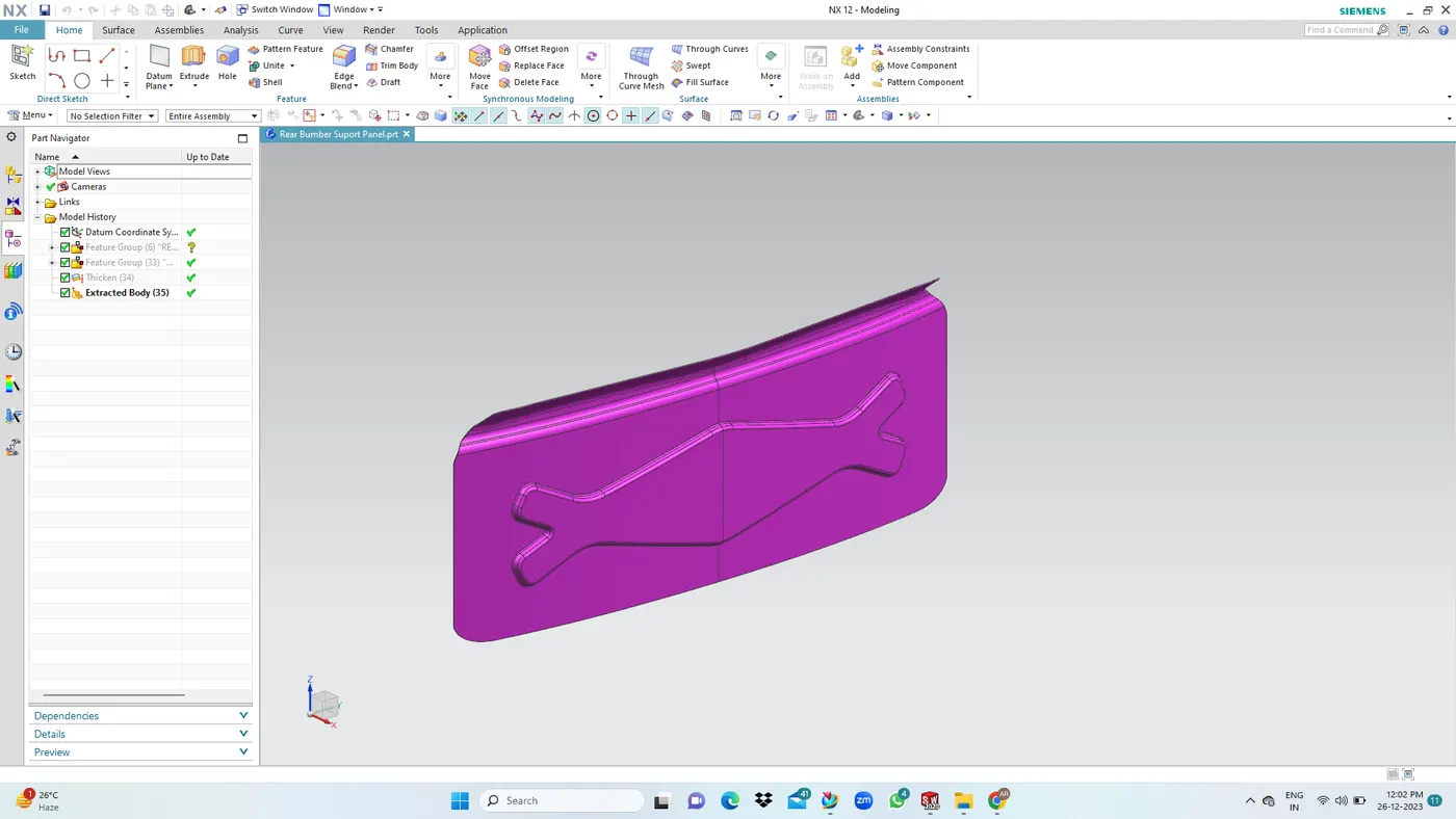
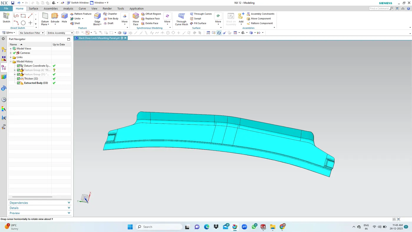
5. Latch Mounting Panel: In this panel on top is mounting latching mechanism. and its joining to frame and rear body.
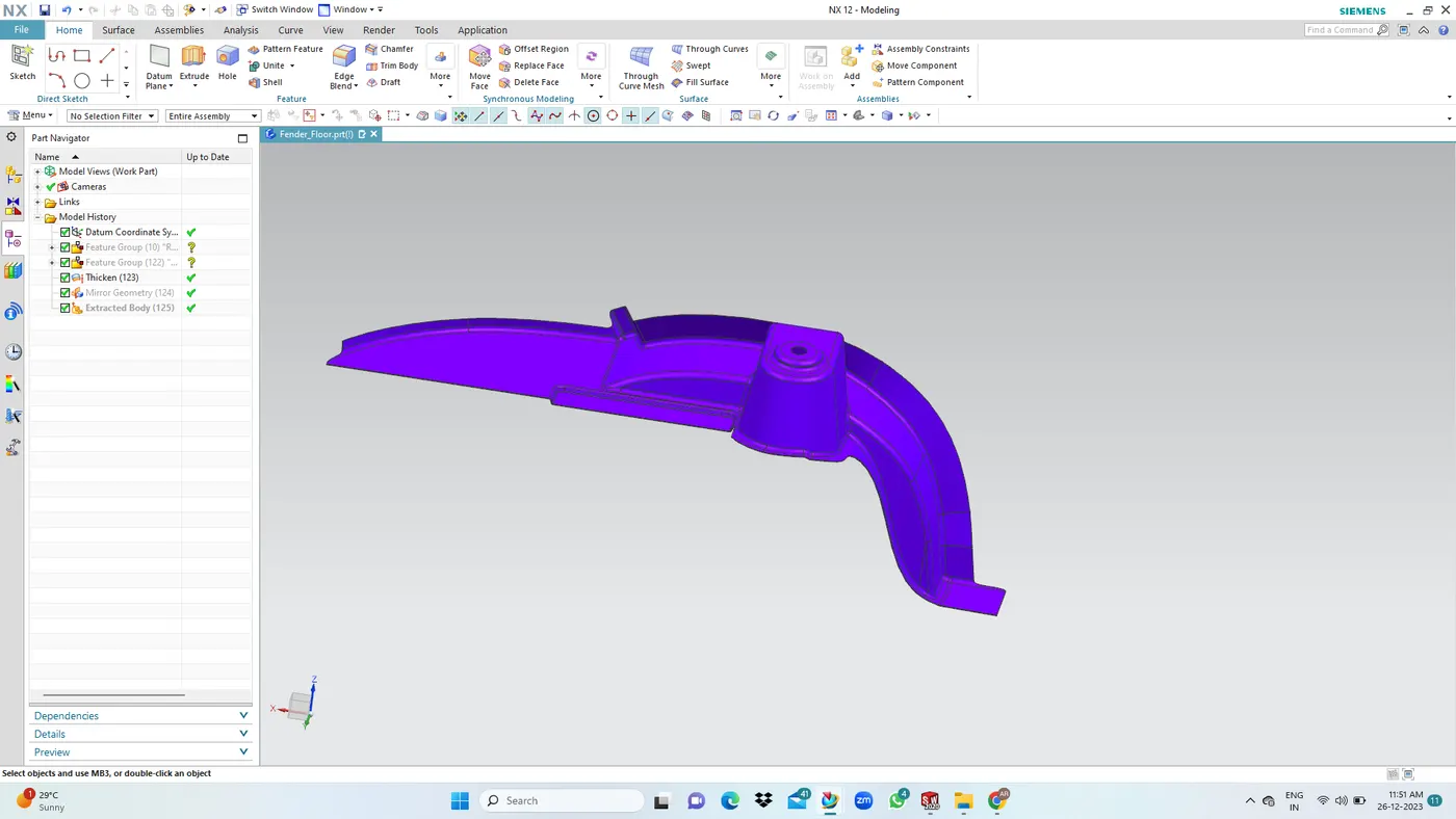
6. Fender Floor: Shock absorber are plased in this area.
Rear Body Assembly:
- Rear Body Assemby consist of a Rear-Body panel and two connecting panel (Connecting the body side outer and the Raer body panel).
- Rear body panel is the first part in the floor assembly which will be subjected to impact in case of raer crash.
- It is supprted with the rear floor panel , Side-body outer and the rear frame
TUNNEL ASSEMBLY:
Tunnel structure in a car is designed for accommodating drive unit parts, and is't arranged in the floor center of a passenger motor vehicle extending in the vehicle longitudinal direction.
Its integrated with the floor and the frame assembly.
It usually accomodates the propellor shaft for front engined and rear wheel drive vehicles and in other car it is udes for exhaust routing.
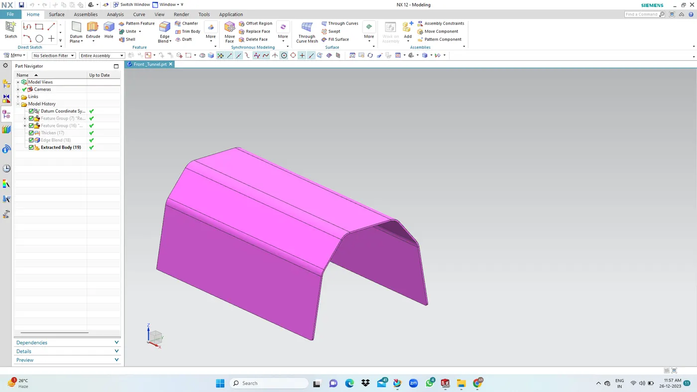
1. Front Tunnel: Front floor joining.
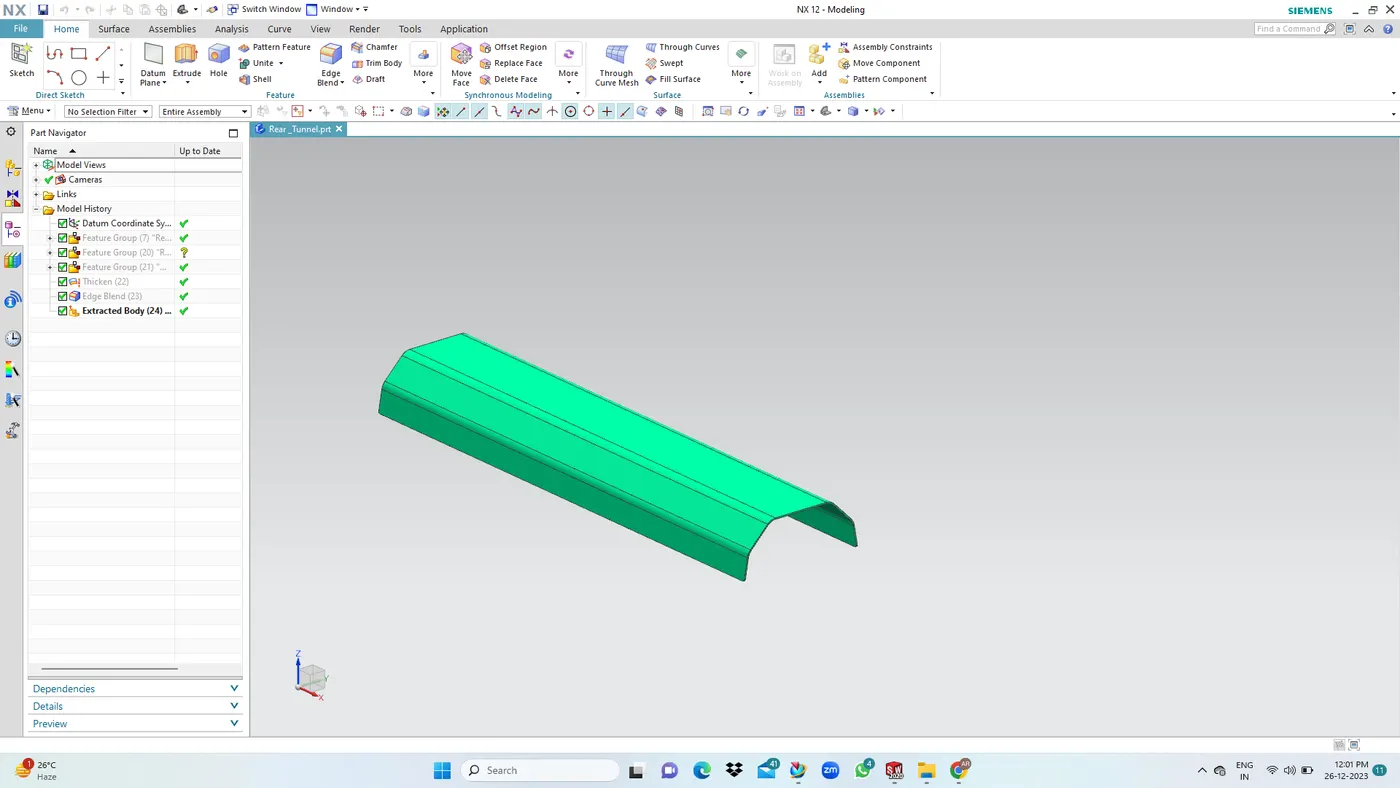
2. Rear Tunnel: Rear frame joining & floor joining.
3. Front and Rear Connecting Tunnel: Bridges the front and rear tunnel.
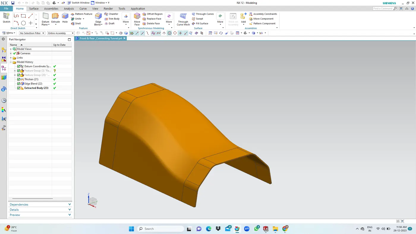
4. Front & Dash Panel Conneting Tunnel: Gear box placement & Dash panel joining.
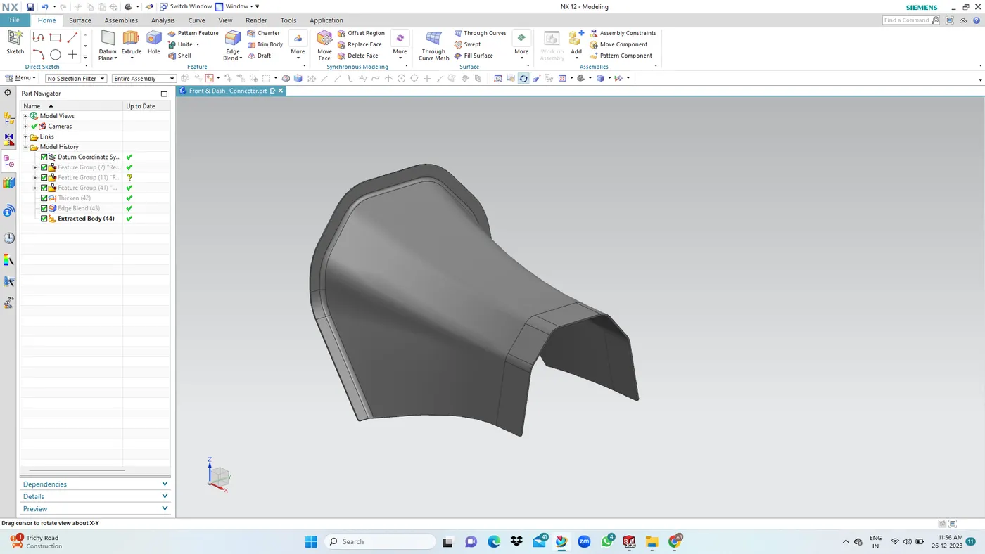
Front Floor & Tunnel Integration: Preferrred method - Spot welding
Spot welds are applied at multiple places along the joining flanges of both parts. Sheet metal requirements for sopt weld.
- Optimum material thickness range 05-3.5mm.
- Minimum clearance for the weld gun to perform the action - 15mm.
FRAME ASSEMBLY:
A vehicle frame is the key part of that car's chassis. All of the other motor vehicle components are attached to the frame. The frame is fastend together with the chassis.
Few functions of the vehicle frame.
- Supporting the vehicle's body and mechanical components.
- Dealing with dynamic and static loads without undue distortion or deflection.
- Supporting the weight of the vehicle passengers, cargo loads, and the weight of the vehicle's body.
- A frame also deals with the torsional and vertical twisting that is transmitted when the vehicle goes over uneven surface.
Few adjacent BIW components integrated with the Frame assembly are Side-body Inner and Outer panels, Floor assembly, Tunnel assembly, Rar body assembly, Etc
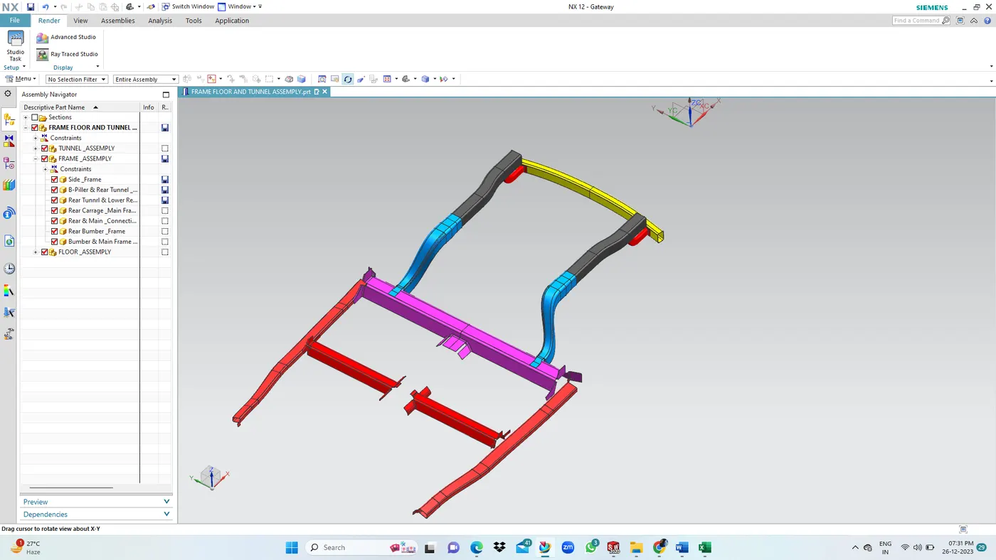
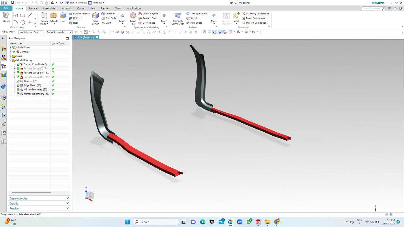
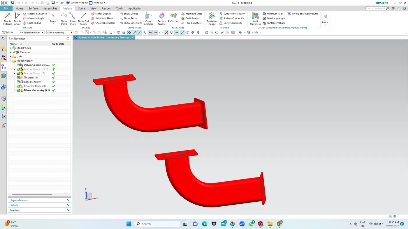
1. Side Frame LH & RH: Add strength to the side body assembly and improve the side impact strength. Integrated with side-body inner and side-body outer panel.
2. Front Frame LH & RH: To add strength to the front floor and improve the side impact strength. Integrated with side-body inner and side-body outer panel. Then Front seat mount by using Rubber sealant.
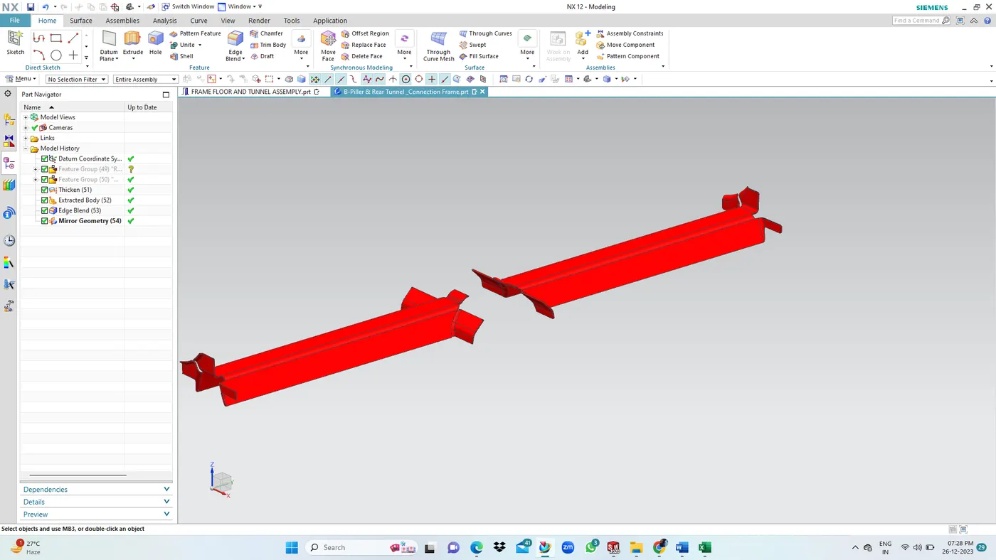
3. Middle Frame: Supports the front floor and rear frame assembly. Integrated with Side-body inner panel.
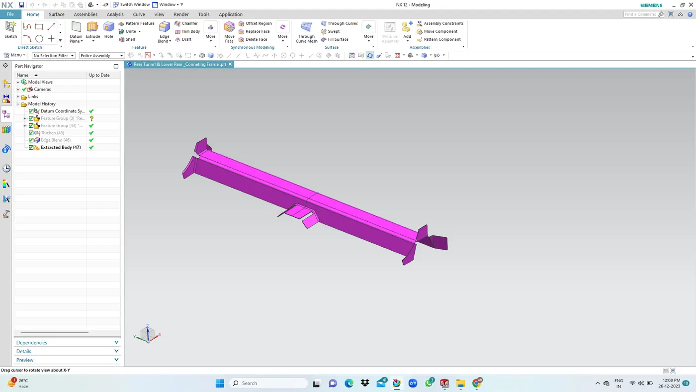
4. Rear Frame LH & RH: Supports the spare wheel panel and the latch mounting panel, and join the middle frame.
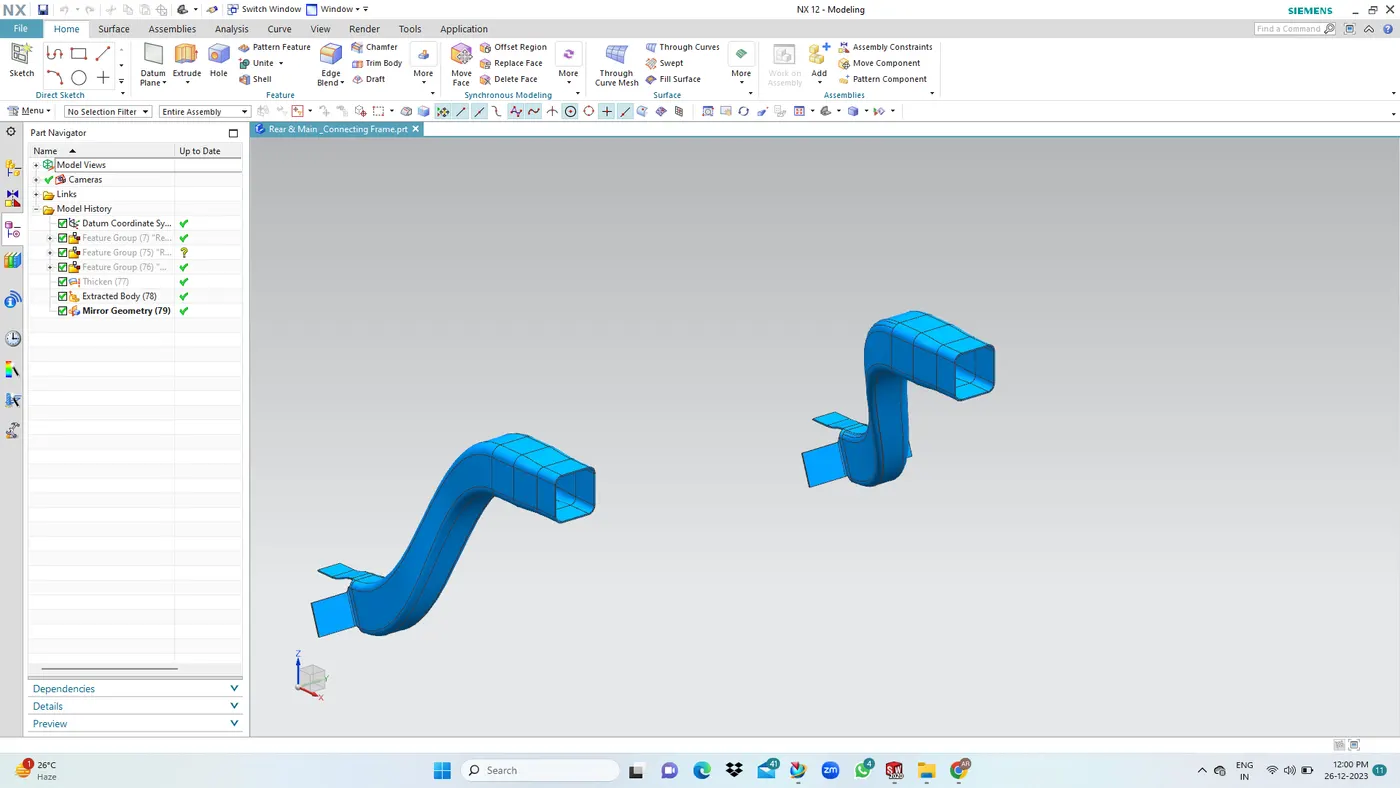
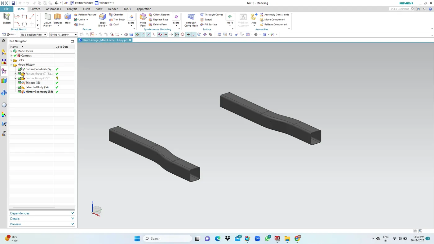
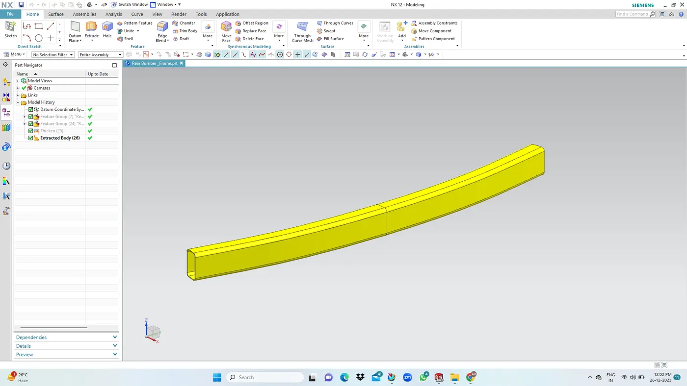
5. Rear Bumber Frame: To give strength the rear bumber and improve the rear impact strength. Box shafe for maximum strength.
Front Floor & Tunnel Integration: Preferrred method - Spot welding
Spot welds are applied at multiple places along the joining flanges of both parts. Sheet metal requirements for sopt weld.
- Optimum material thickness range 05-4mm.
- Minimum clearance for the weld gun to perform the action - 15mm.
DESIGN CONSIDERATION:
1. Seat Mount: We are maintained to provide more space for the passengers and sit comfortable. Seat mounting can be provided on the frame by directly mounting the seat on the front frame or by creating a separate sheet metal mounting. The mounting can be attached to add extra strengths to seat mounting.
2. Side Impact of Frame: In case of the side impact the force deviated and travels throughout the frame structure and guided towards the center. The side frames take the brunt of the impact and the residual forces are diverted through the frames in between the front floor.
3. Rear Impact: In case of the rear impact the first part of the frame which bears the load is the rear bumber support, and from there the force travels towards the side frame through the raer frame assembly. This design deviates the load away from the passengers and increasing the overall safety of the car.
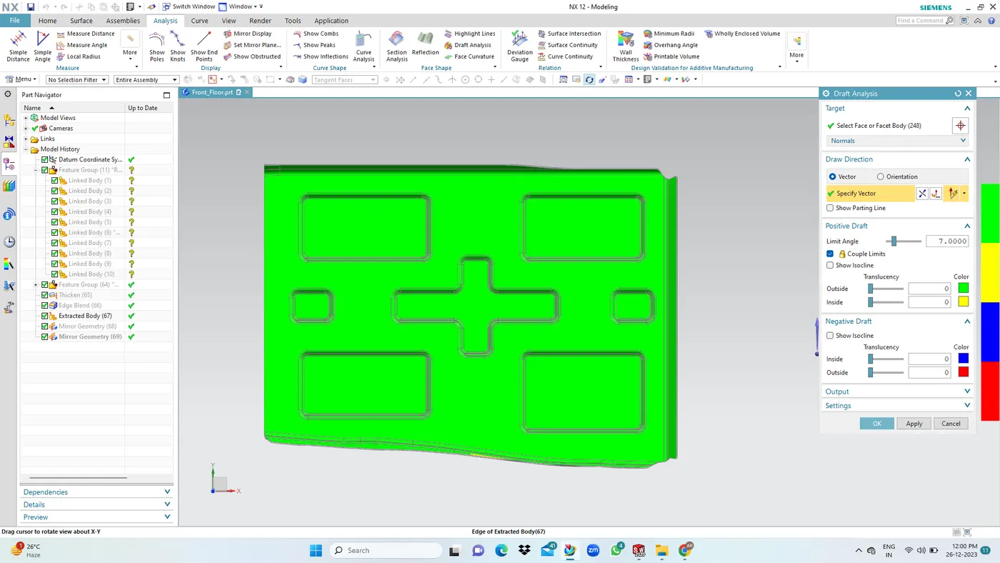
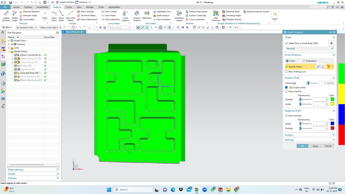
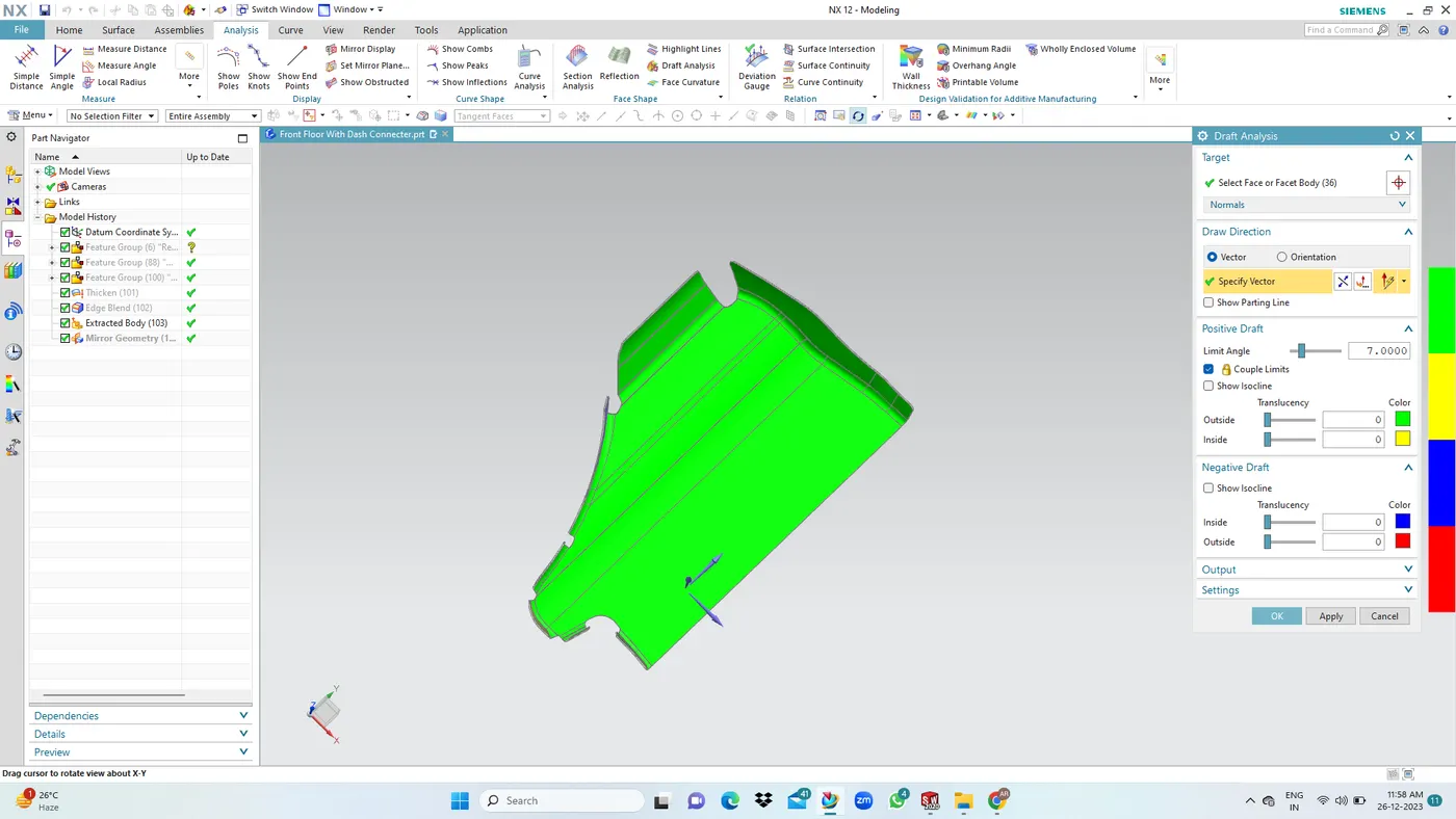
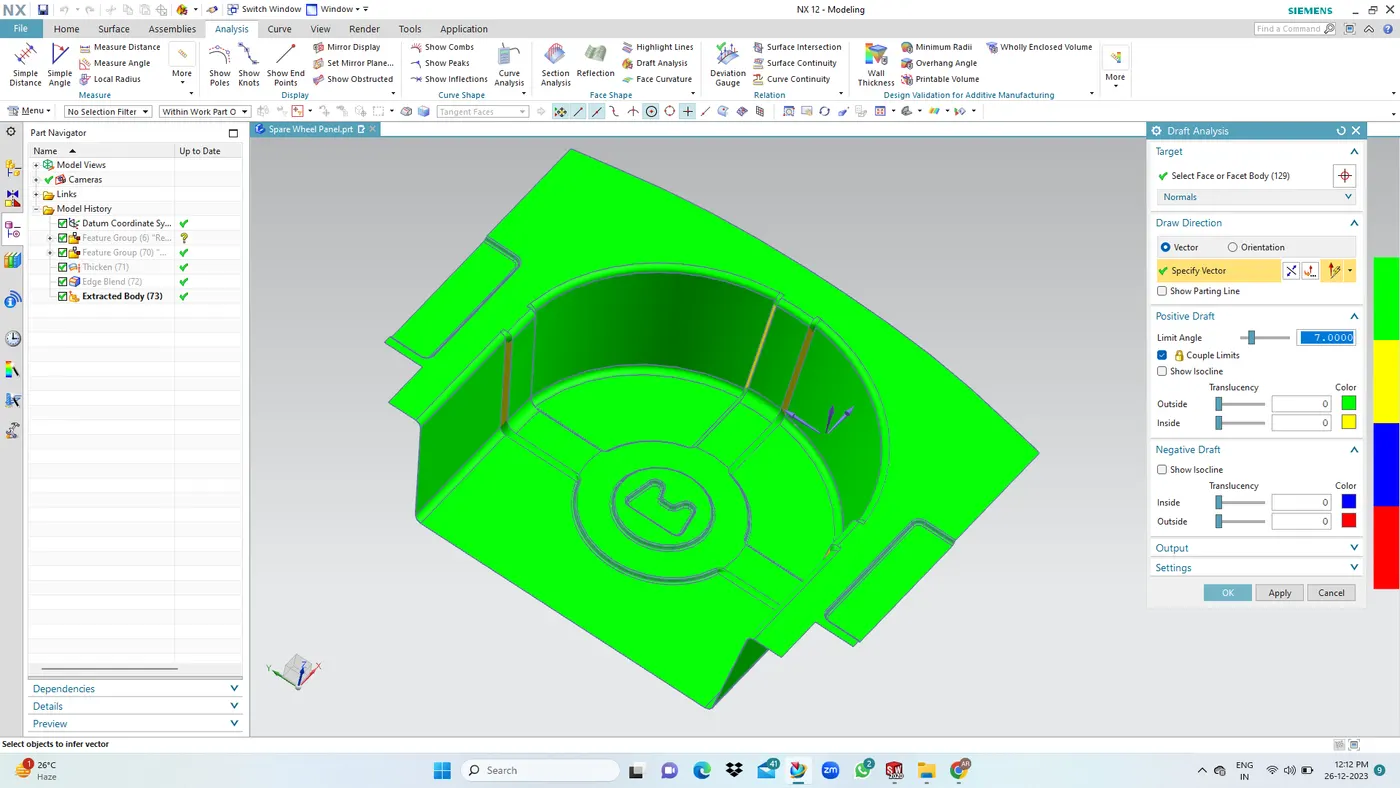
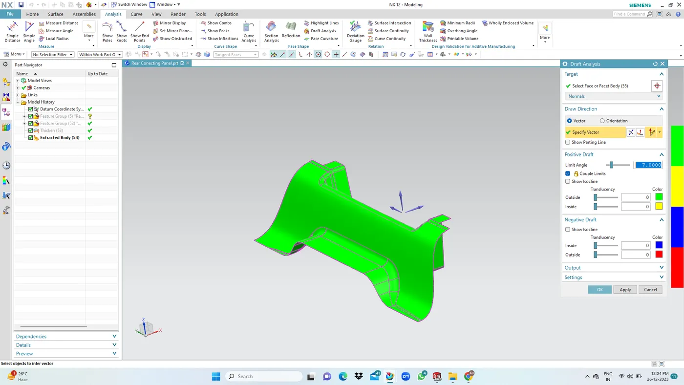
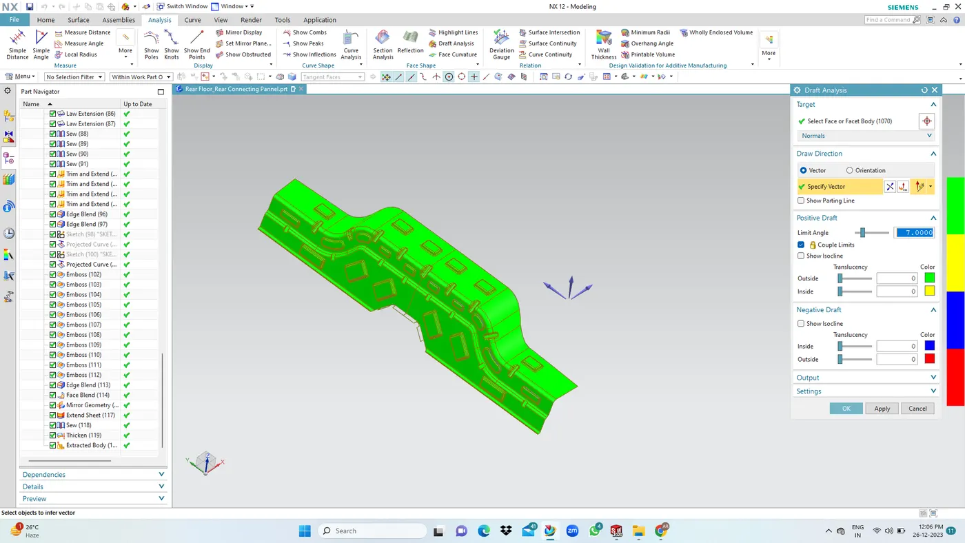
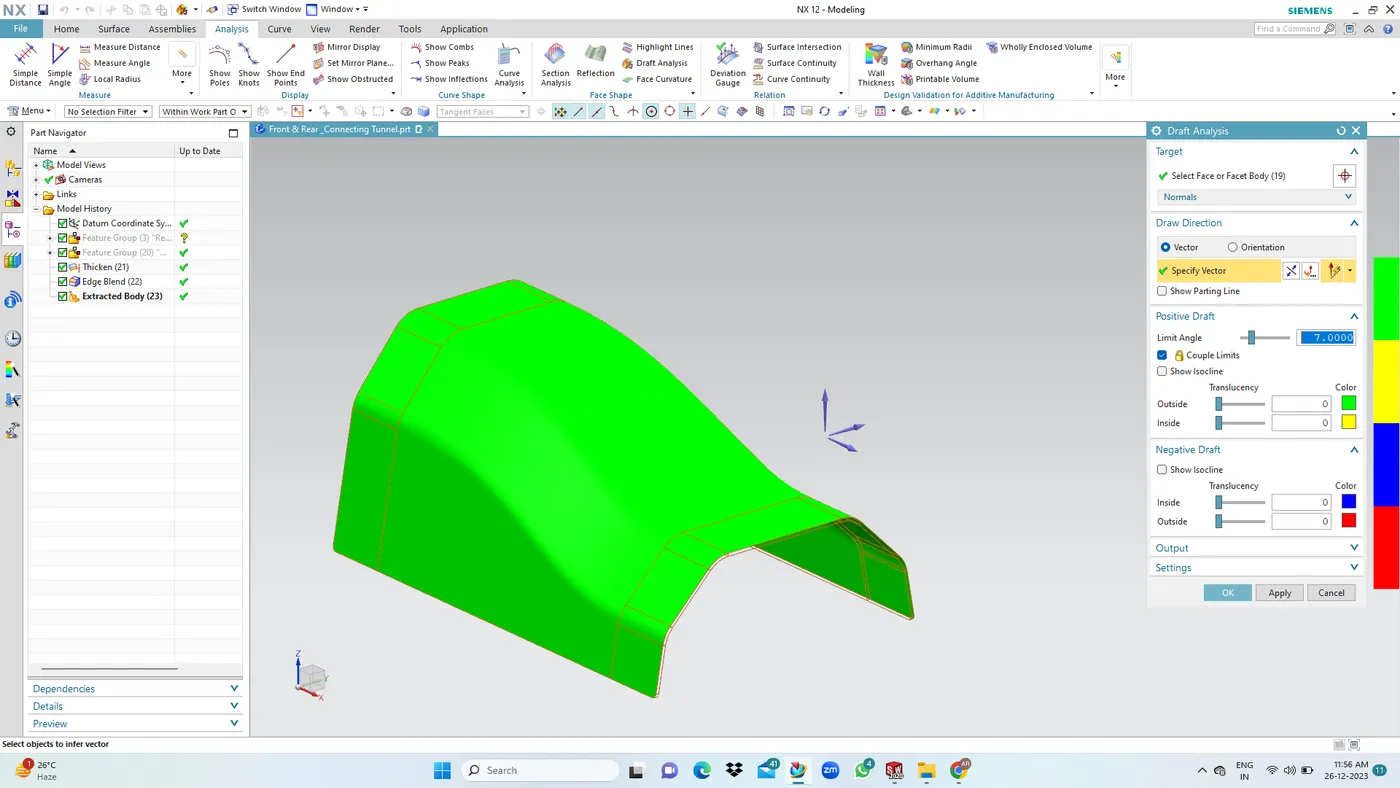
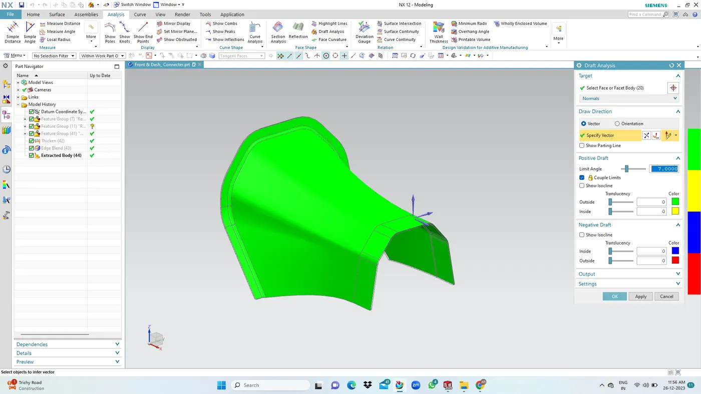
DRAFTING ANALYSIS: WE are apply the minimum positive draft angle 7 degree of below the components.
FLOOR ASSEMBLY:
1. Front Floor LH & RH:
2. Middle Floor LH & RH:
3. Reinforcements LH & RH:
PANEL ASSEMBLY:
1. Spare Wheel Panel:
2. Rear Connecting Panel:
3. Rear Floor & Rear Connecting Panel:
4. Rear Body:
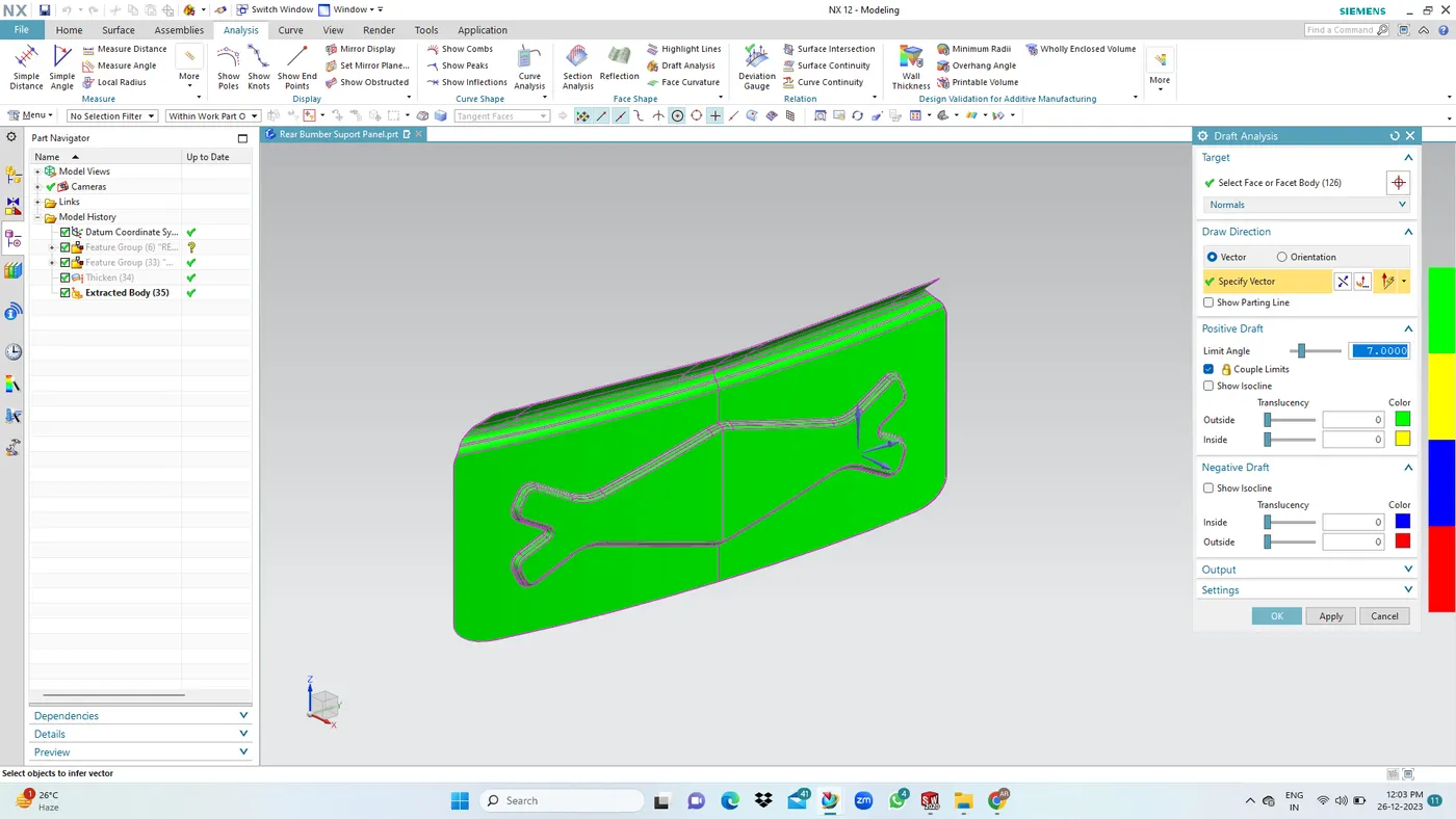
5. Latch Mounting Panel:
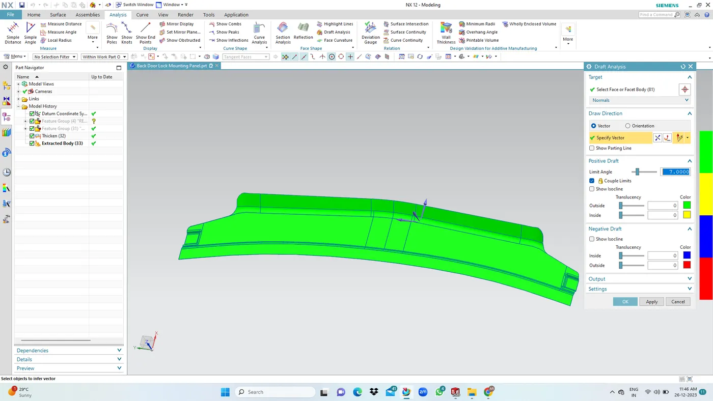
TUNNEL ASSEMBLY:
1. Front Tunnel:
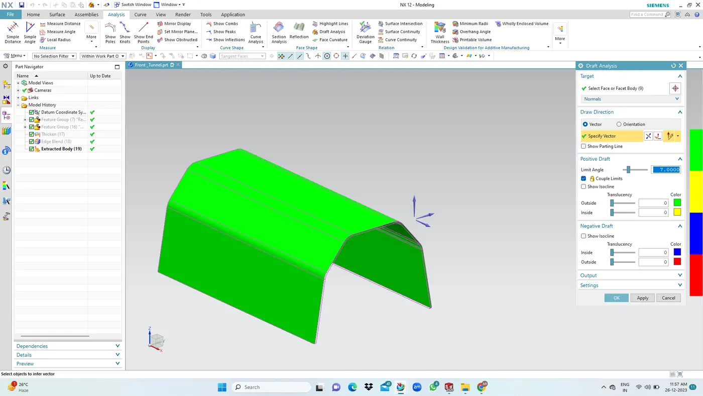
2. Rear Tunnel:
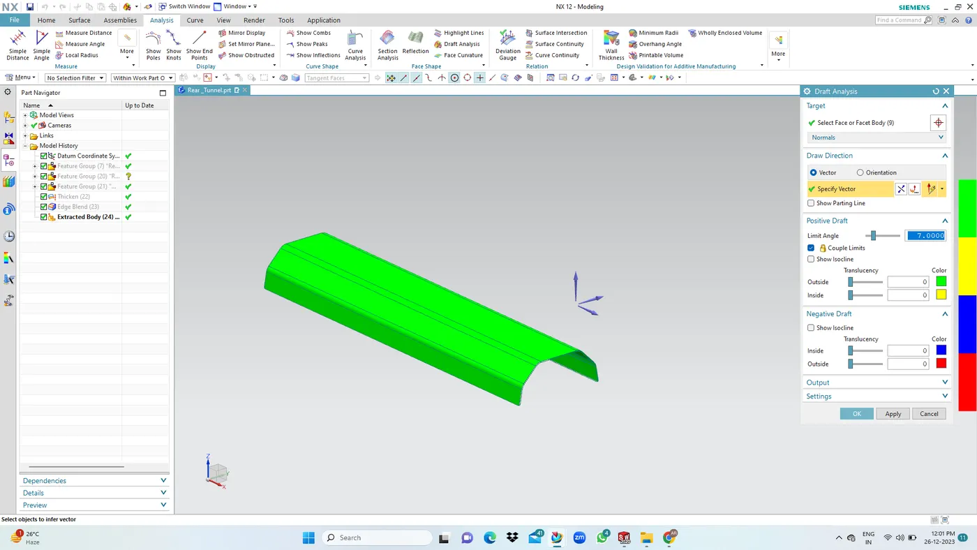
3. Front and Rear Connecting Tunnel:
4. Front & Dash Panel Conneting Tunnel:
MANUFACTURING PROCESS: The stamping process is a metal forming process in which sheet metal is given a desired shape. The stamping process may include diffrent other sheet metal operation like punching, bending,blanking,shearing, etc.
CONCLUSION:
Design and develop the frame, floor, and tunnel assemply was completed with required reinforcement and design consideration by usng NX CAD is done.
Hear i attached drive link.
https://drive.google.com/file/d/1NiVvsB9HwoFvk1V0cqfN3AtX3FNHHqdM/view?usp=sharing