Foundation Design using SAFE
Q1. Model the isolated footing provided in week 11 challenge on SAFE. Analyze and design it to verify the size, depth and steel provided as per calculations.
ANS :
AIM : To analyze and design the isolated footing from week 11 challenge using SAFE and to verify the size, depth and steel provided as per calculation
PROCEDURE :
Data Required
Unfactored load = 2000/1.5 = 1333.33 KN
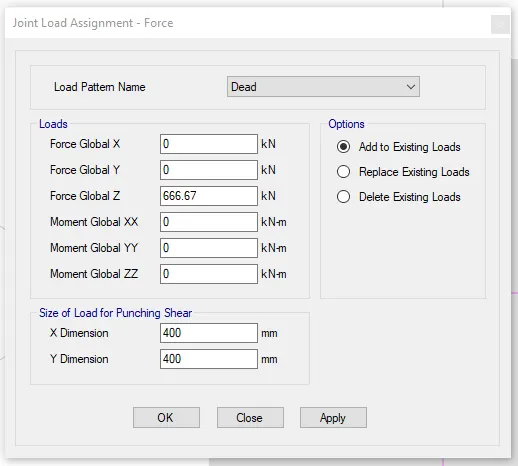
Dead load breakup = 1333.33/2 = 666.7 KN
Live load breakup = 1333.33/2 = 666.7 KN
Subgrade modulus of soil = Safe bearing capacity x factor to ultimate / maximum settlement
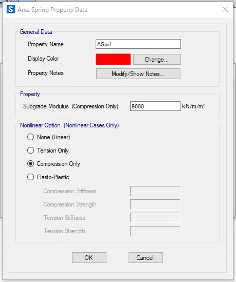
Subgrade modulus of soil = 150 x 3 / 0.05 = k = 9000 KN/cum
Rebar yield strength (Fy) = 500 N/mmsq
Rebar ultimate strength (Fu) =575 N/mmsq
Elastic modulus of M25 concrete = 25000 N/mmsq
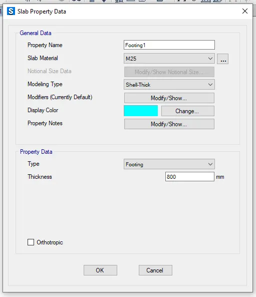
Thickness of concrete footing = 800mm
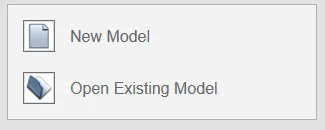
Step 1 : Open the SAFE software and select new model
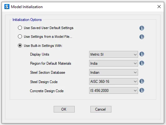
The model initialization dialogue box will appear in that do the appropriate setting
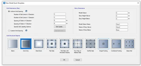
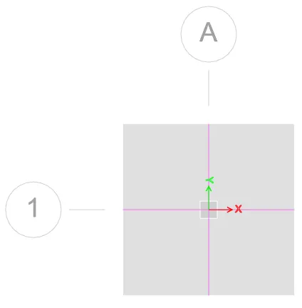
New model quick template will appear in that select single footing and give the values as per the calculation done and click OK
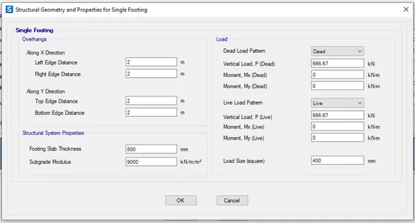
Step 2 : Now we should define Material Property
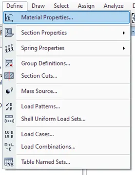
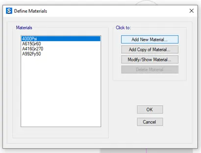
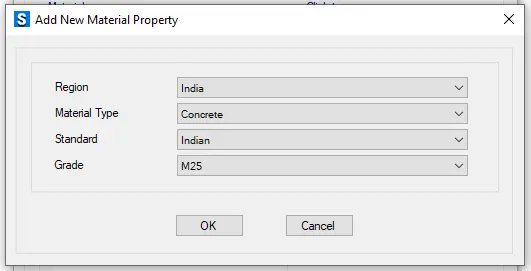
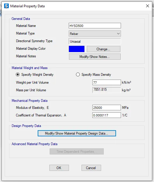
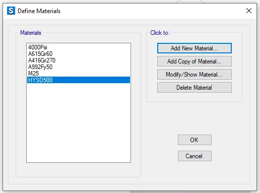
Go to Define tab in that select material properties in that add new material property and add required material
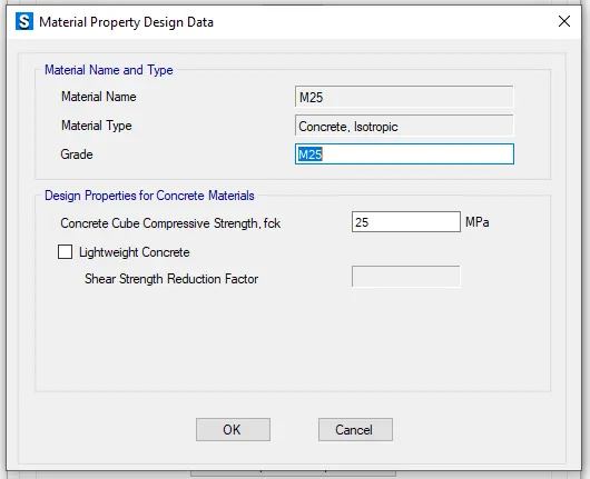
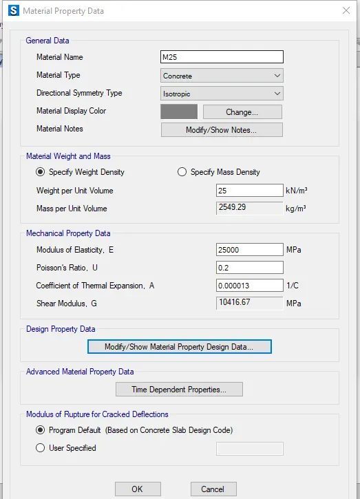
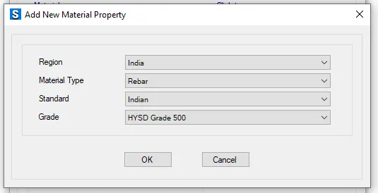
Material property data :
Click define followed by material properties
M25 grade of concrete

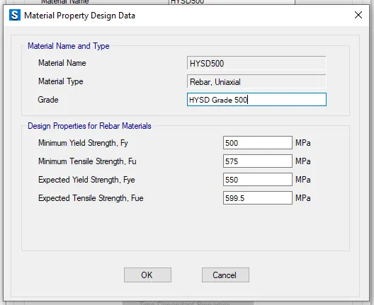
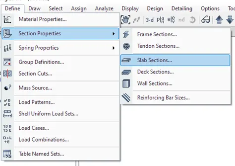
Step 3 : Go to define tab in that select section properties and select slab sections
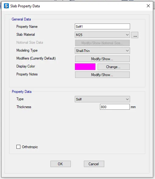
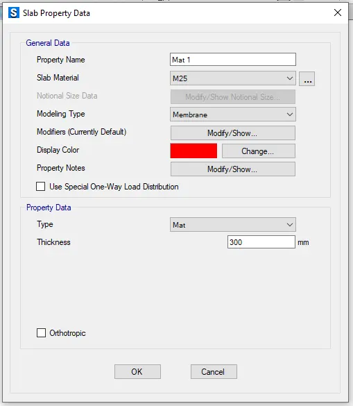
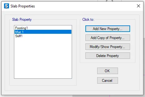
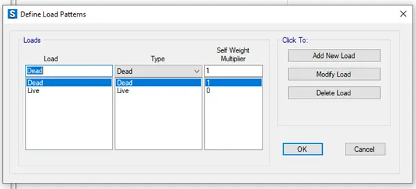
Step 4 : Go to define tab and select load pattern
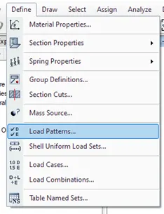
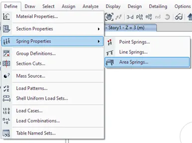
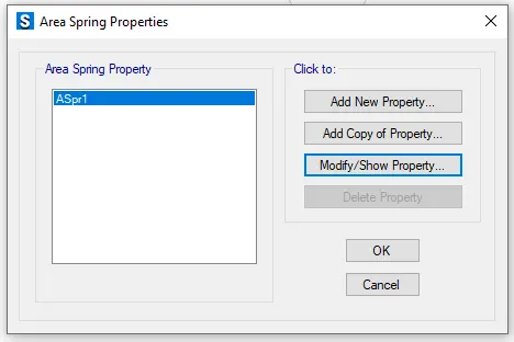
Step 5 : Go to define tab select spring properties in that select area spring
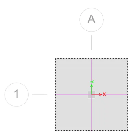
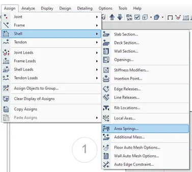
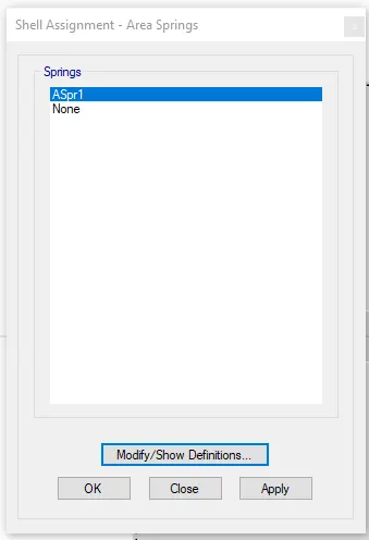
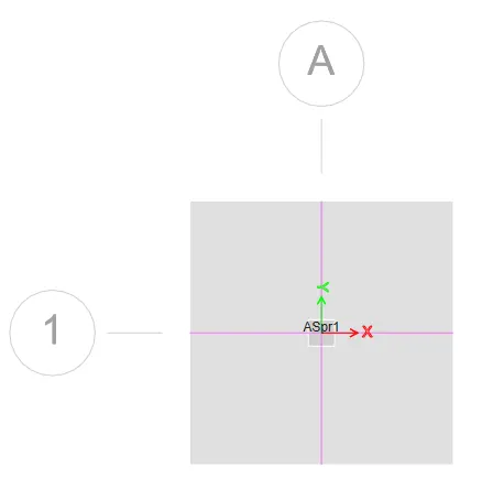
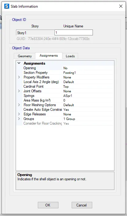
Assign the spring load to the slab
Go to assign tab select the shell in that select area spring and assign the area spring load to the slab
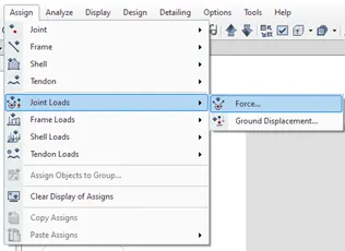
To assign loads go to assign tab select joint loads and select force
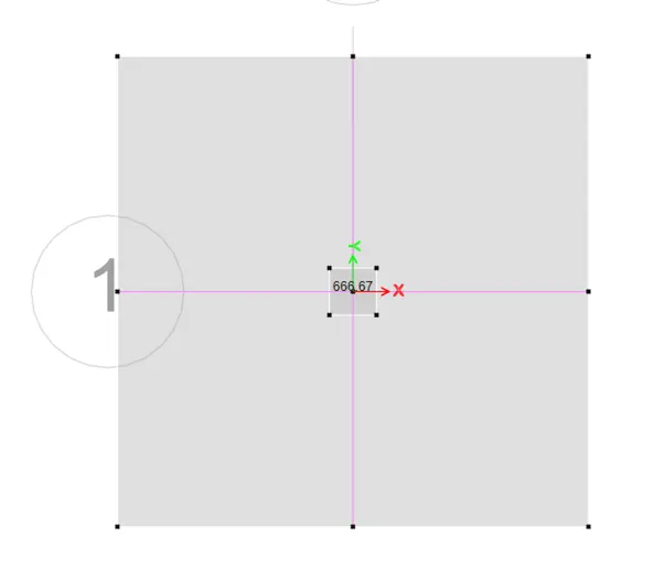
Add live load and dead load
Step 6 : Go to define tab select load combinations and add the load combination
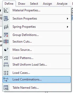
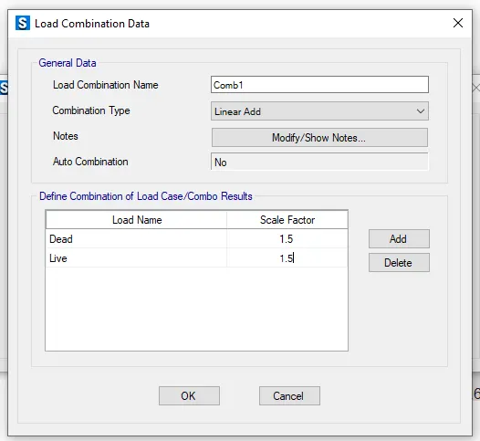
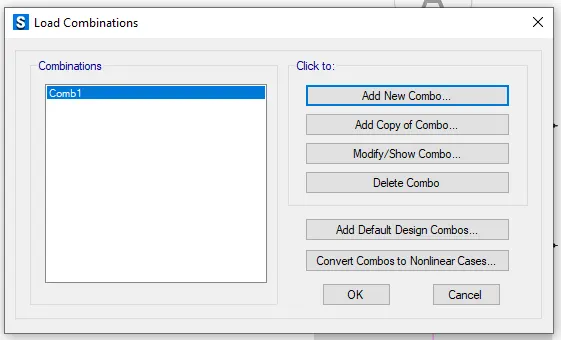
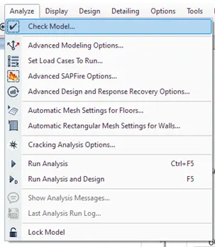
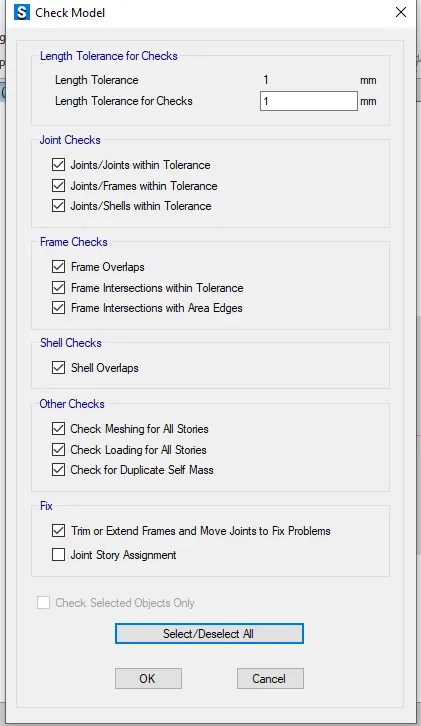
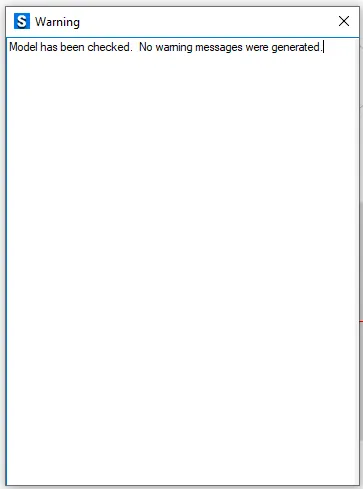
Step 7 : Go to analyze tab and select check model for errors
Step 8 : Run the analysis
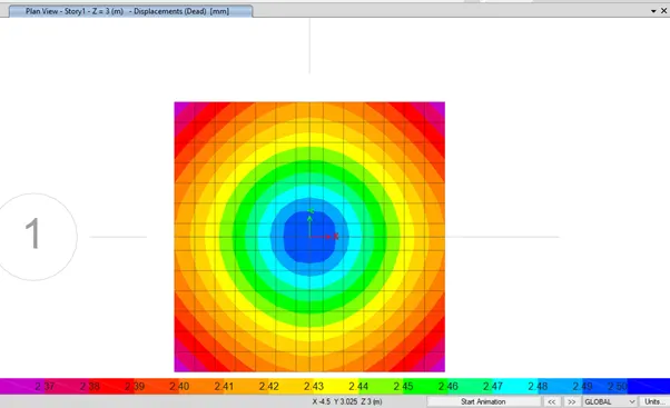
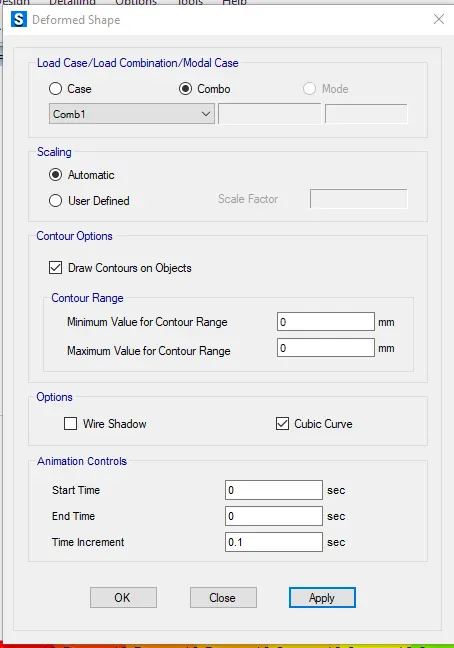
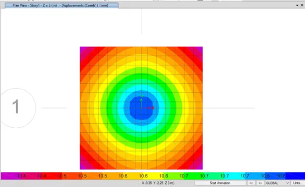
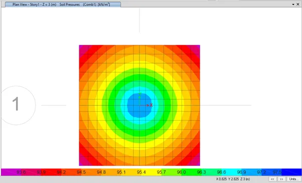
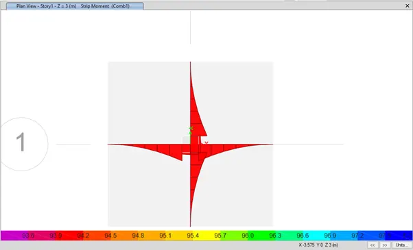
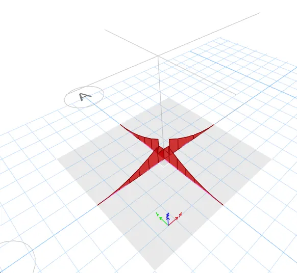
For deformed shape at load combination 1
RESULT :
Isolated footing is designed using safe software
Q2. A column of size 600x600 carrying an unfactored gravity load (DL+LL) of 1175 KN is to be supported on pile cap, which ultimately transfers load to the piles underneath. Piles of 16 metres length and 500 mm diameter are to be used. Each pile has a load carrying capacity of 200 KN. Model, analyse and design the pile cap on SAFE to evaluate the following:
- Pile group to be used
- Depth of pile cap
- Longitudinal steel on top and bottom face in both directions
ANS :
AIM : To Model, analyse and design the pile cap on SAFE and to evaluate the following:
- Pile group to be used
- Depth of pile cap
- Longitudinal steel on top and bottom face in both directions
PROCEDURE :
Required calculation
Given data :
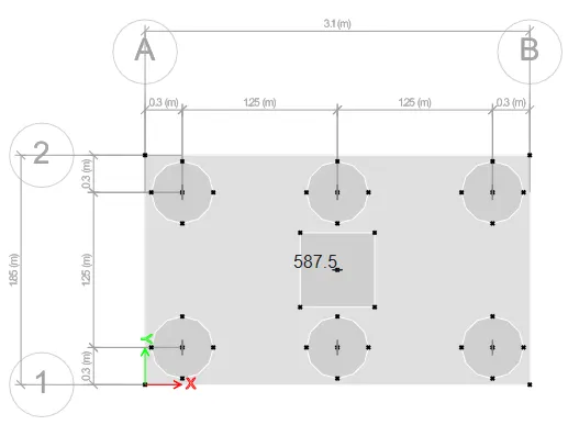
Column Size = 600 x 600 mm
Unfactored load = 1175 KN
Pile length = 16 m
Pile diameter = 500 mm
Load carrying capacity = 200KN
Number of pillars = 1175/200 = 5.87 = 6 Nos.
Spring constant = (EA)/L
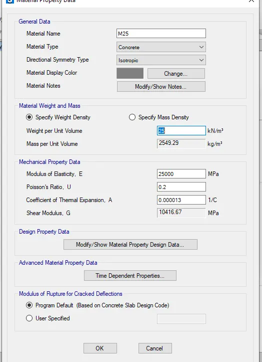
Where E = 25000 N/mmsq
Area, A = π /4 = π /4 = 196349 mmsq
Pile length, L = 16000 mm
Spring constant = (EA)/L = (25000 x 196349)/16000 = 306795 N/mm
Edge spacing is taken as 300mm
Step 1 : Open the SAFE software and select new model
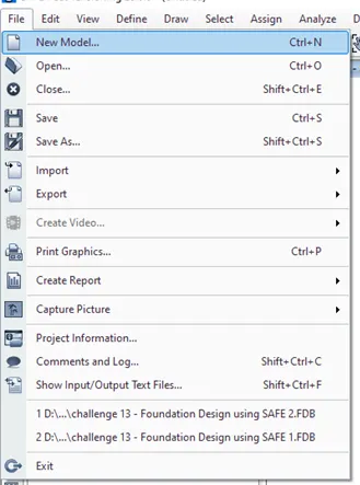
The model initialization dialogue box will appear in that do the appropriate setting
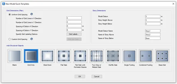
New model quick template will appear in that select grid only and give the values as per the calculation done and click OK
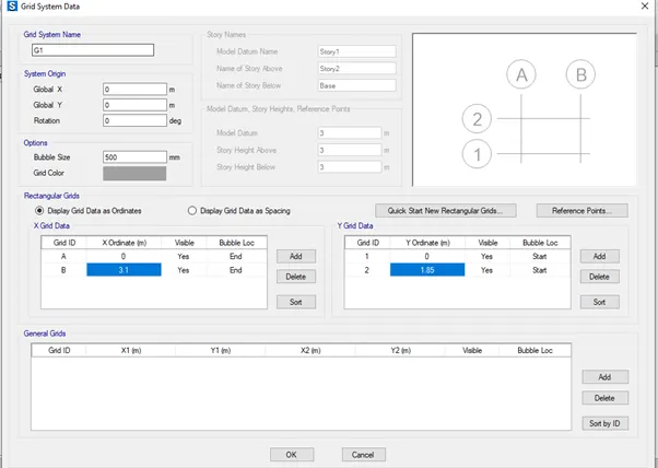
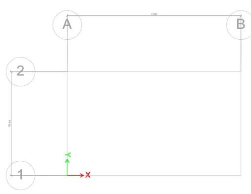
Step 2 : Now we should define Material Property
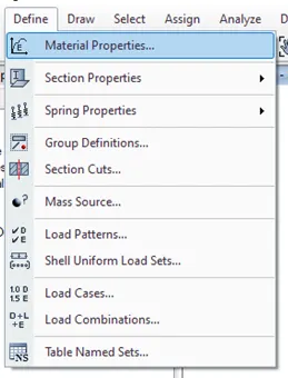
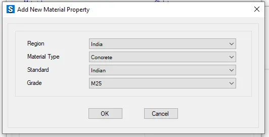
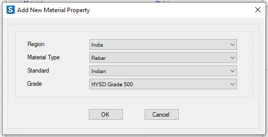
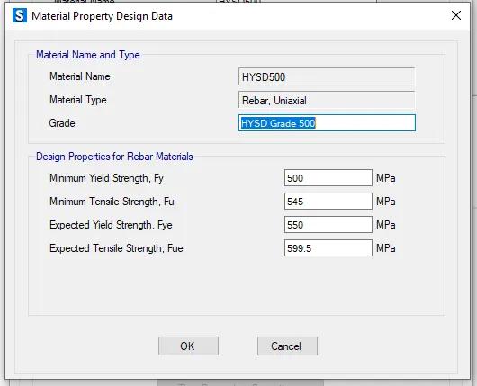
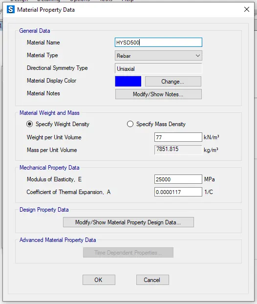
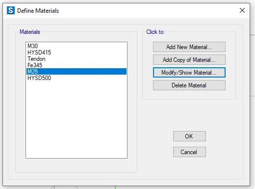
Go to Define tab in that select material properties in that add new material property and add required material
Material property data :
Click define followed by material properties
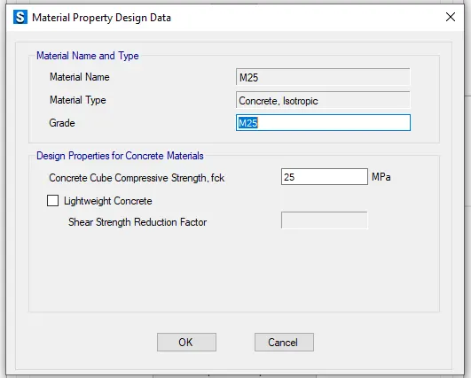
M25 grade of concrete

Step 3 : Go to define tab in that select section properties and select slab sections
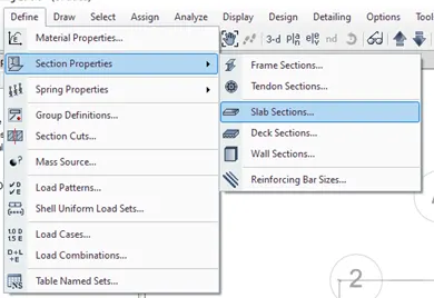
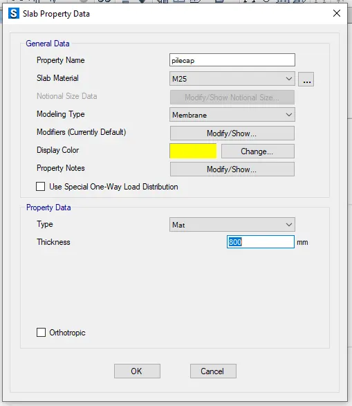
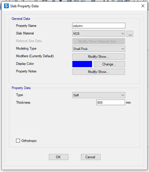
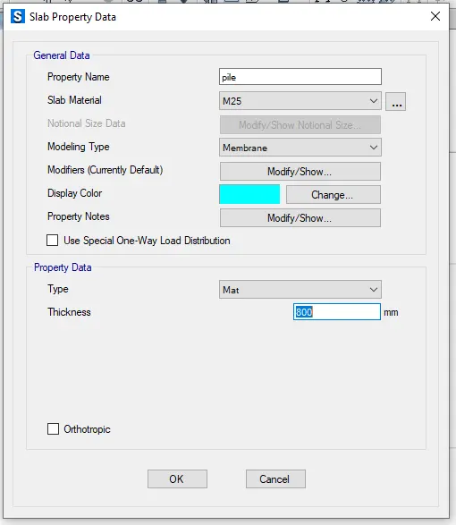
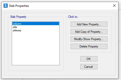
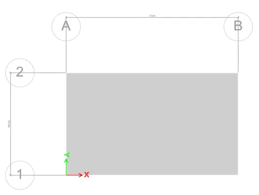
Step 4 : Draw the slab using quick draw slab
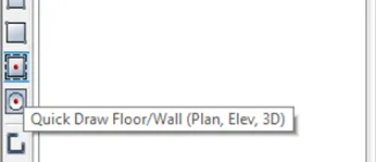
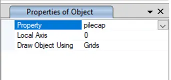
Step 5 : Draw the points
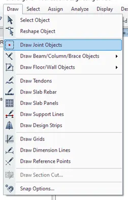
Go to draw tab select Draw joint objects
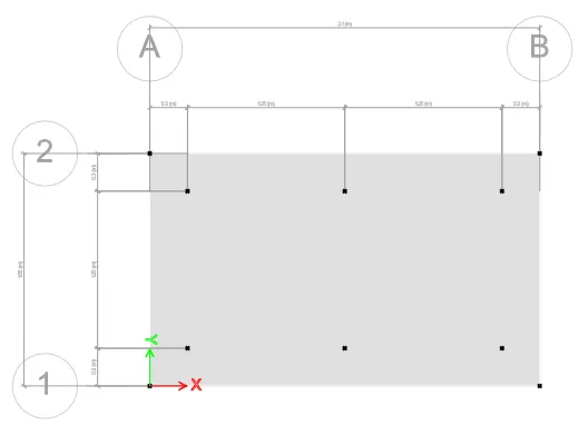
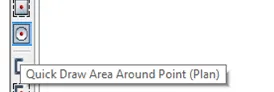
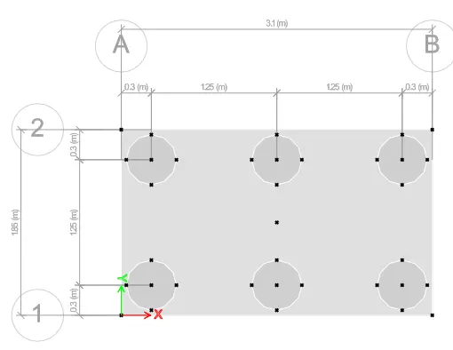
Step 6 : Draw the pile at the points created by using quick draw area around points
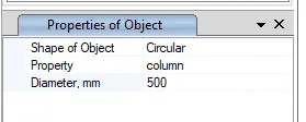
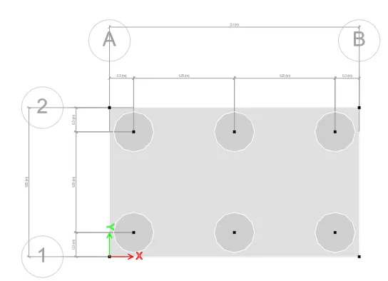
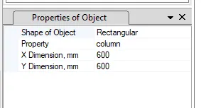
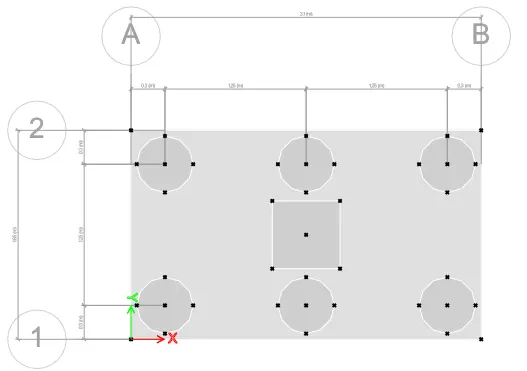
To draw a rectangular column draw the point at the middle and draw the column of size 600 x 600mm
Step 7 : Go to define tab and select load pattern
Step 8 : Go to define tab select spring properties in that select point spring
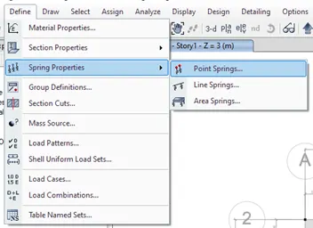
Spring constant = (EA)/L = (25000 x 196349)/16000 = 306795 N/mm = 306.795KN/mm
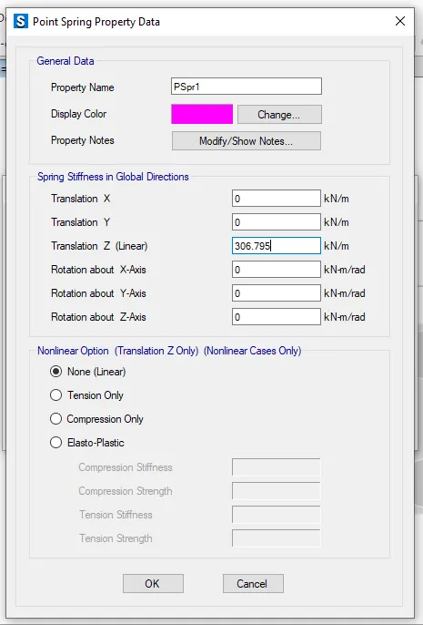
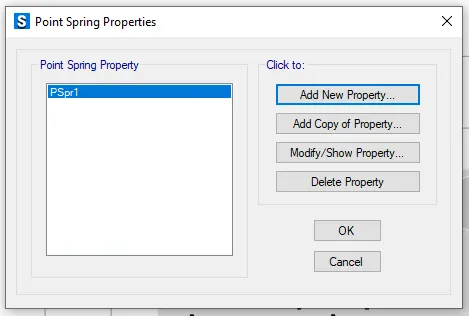
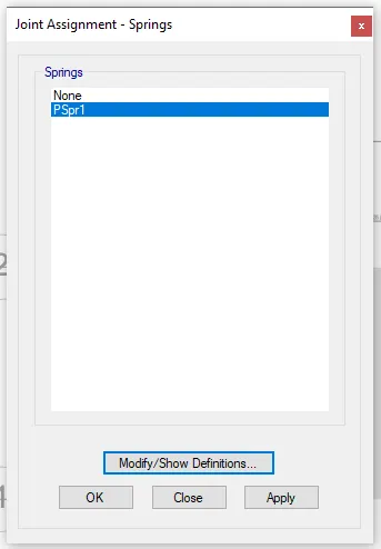
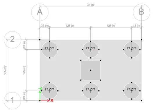
Assign the spring load to the pile
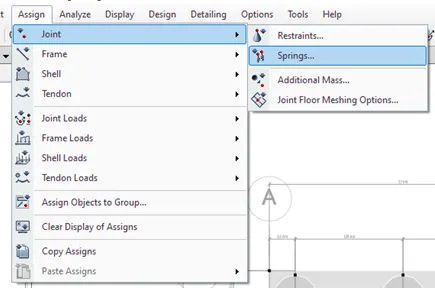
Go to assign tab select the joints in that select point and assign the point spring load to the pile selected
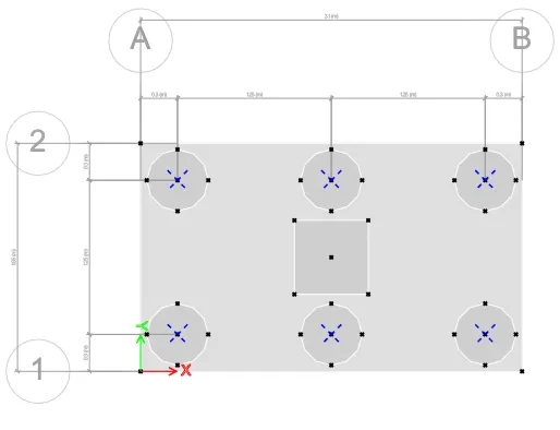
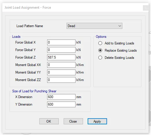
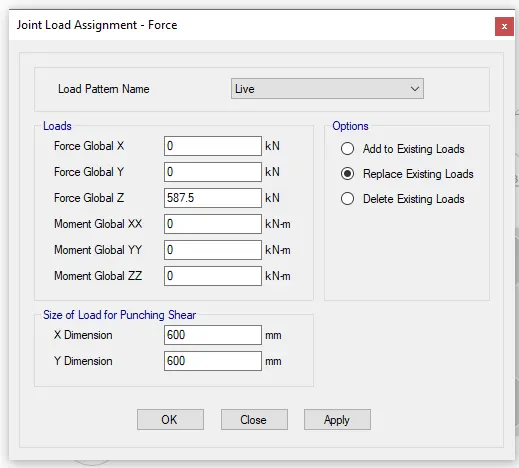
To assign loads go to assign tab select joint loads and select force
Add live load and dead load
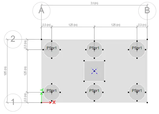
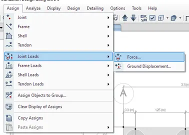
Dead and live load are 587.5 KN
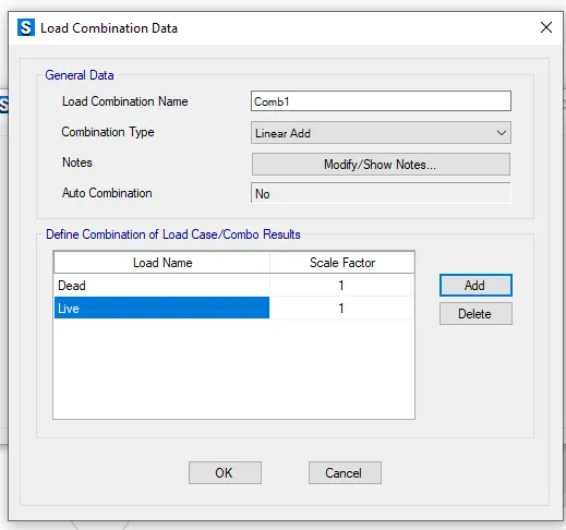
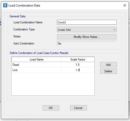
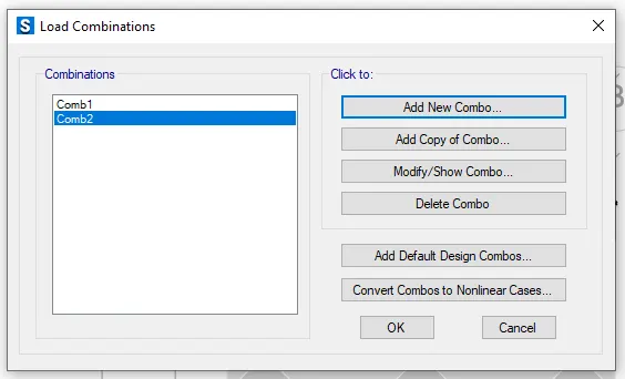
Step 9 : Go to define tab select load combinations and add the load combination
Step 10 : Go to analyze tab and select check model for errors
Step 11: Run the analysis
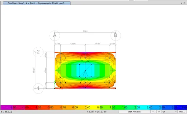
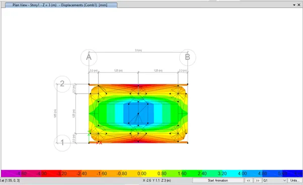
For deformed shape at load combination 1

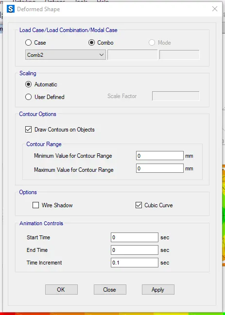
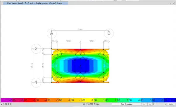
For deformed shape at load combination 2
Pile spring load
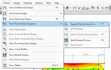
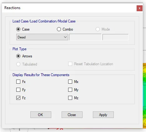
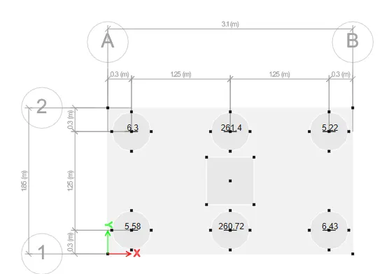
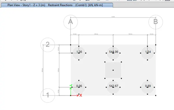
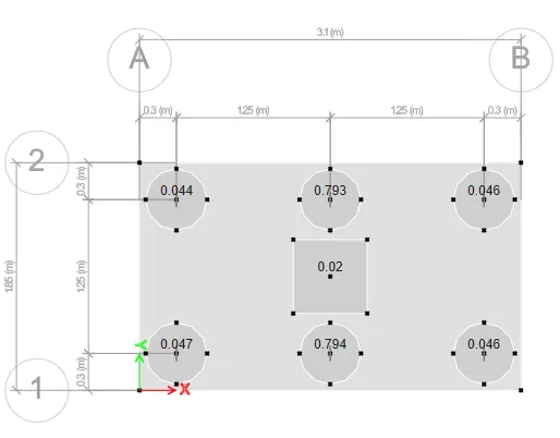
Joint reaction diagram
RESULT :
Pile cap foundation is designed using safe software