Foundation Design using SAFE
Model the isolated footing provided in the week 11 challenge on SAFE. Analyse and design it to verify the size, depth and steel provided as per calculations.
AIM
To model an isolated footing provided in the previous challenge and to analyse and design it to verify the size, depth and steel provided according to the calculations.
DATA EXTRACTED
Size of column = 400mm x 400 mm2
Factored load due to the column = 2000kN
Unfactored load = 2000/1.5 = 1333.33kN
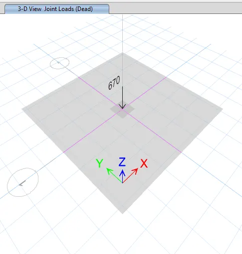
Dead load Breakup = 1333.33 / 2 = 666.67kN
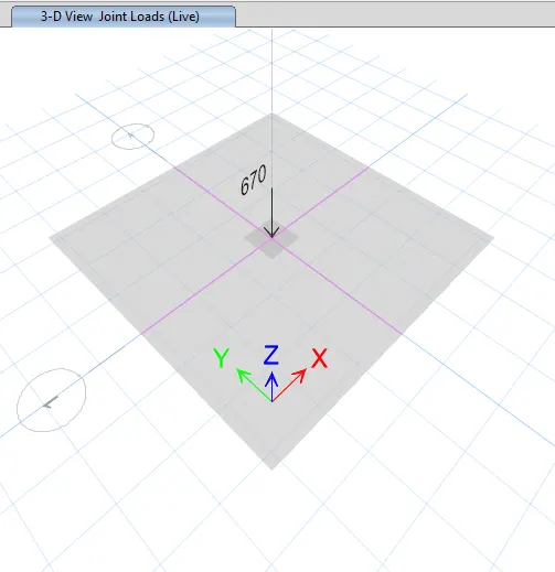
Live load Breakup = 1333.33 / 2 = 666.67kN
SBC at the site = 150kN/m2
Concrete grade = M25
Steel grade = Fe415
Max Settlement = 50mm (IS 1904-1986: Table 1)
Subgrade modulus of soil = SBC x FOS /max settlement
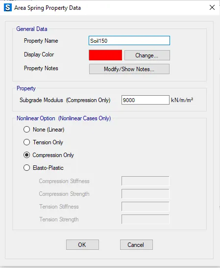
150 x 3 / 0.05 = 9000kN/m/m2
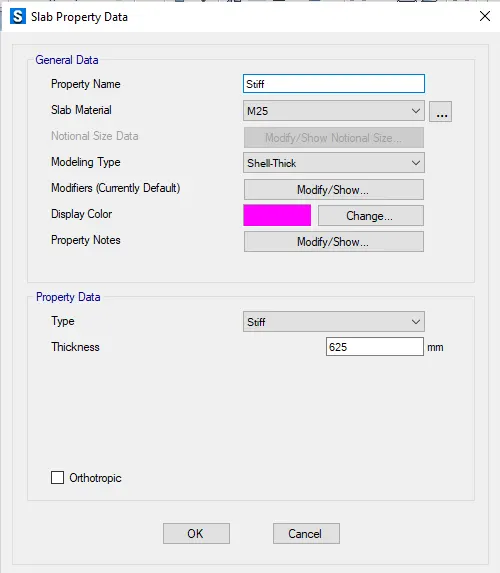
Footing thickness = 625mm
Size of footing = 3.2m x 3.2m
PROCEDURE:
Open SAFE
Click on the new model
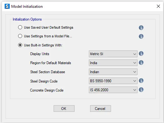
Use built-in settings
Change the units and codes as per Indian standard, click OK
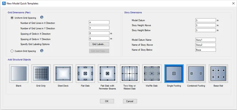
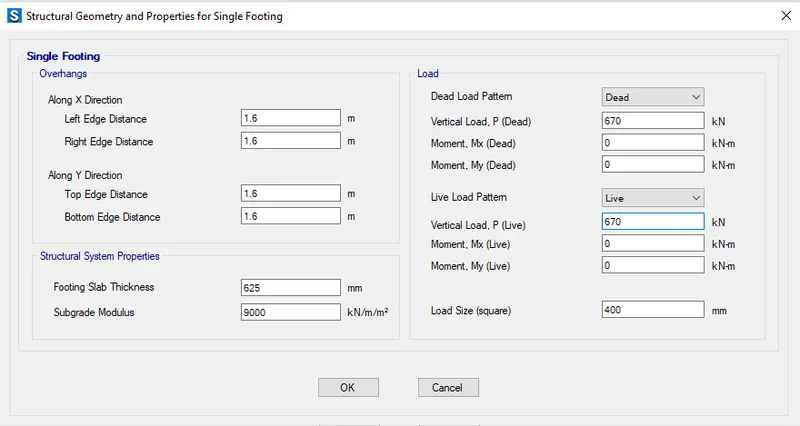
Choose the Single Footing option from the footing templates and provide the footing details
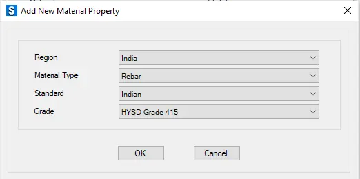
Go to Define> Material Properties> Add New Property
Add M25 grade concrete and Fe415 grade Steel Rebar
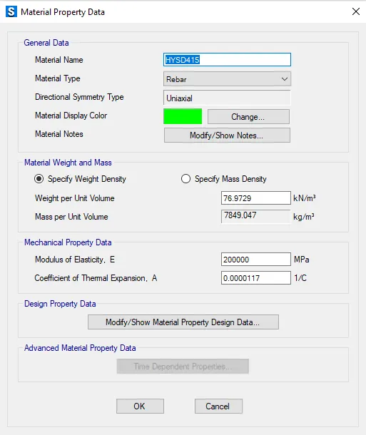
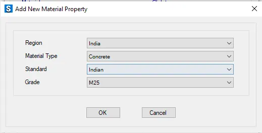
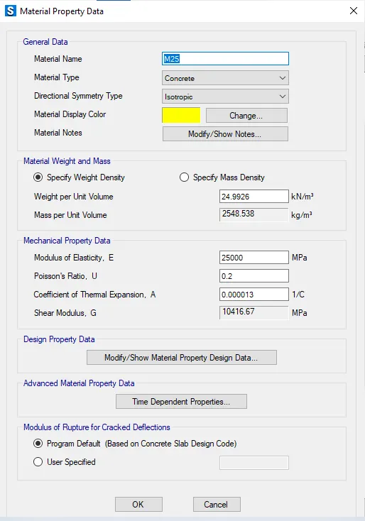
Go to Define> Section Properties> Slab Section> Add New Property
Add Footing Slab and Stiff with the following properties
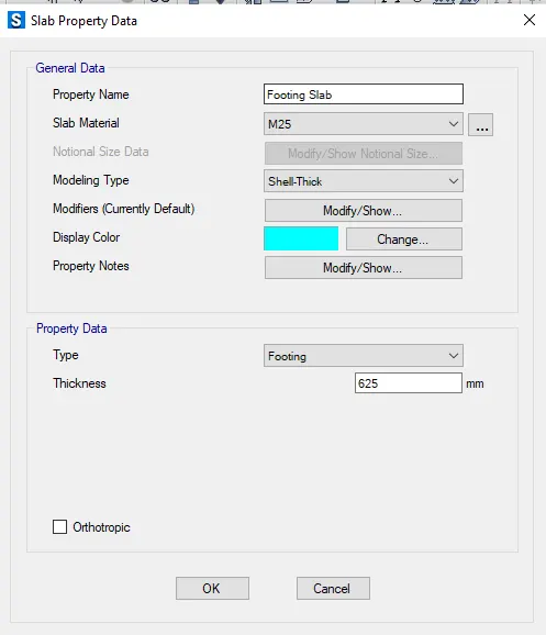
Go to Define> spring properties> Area spring> Add New Property
Add Soil150 with the following properties
Check the assigned loads
Go to Display> Show Load Assigned> Joints
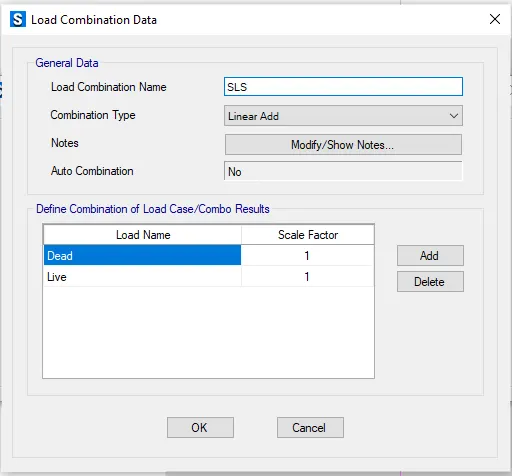
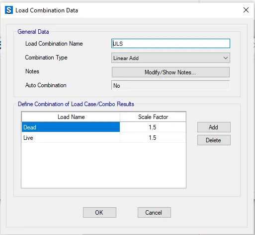
Go to Define> Load Combination> Add New Combo
Add SLS and ULS as shown below
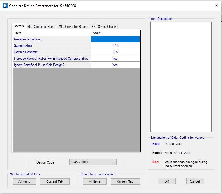
Go to Design> Concrete Slab/ Beam Design> View/ Revise Preferences
Check design preference
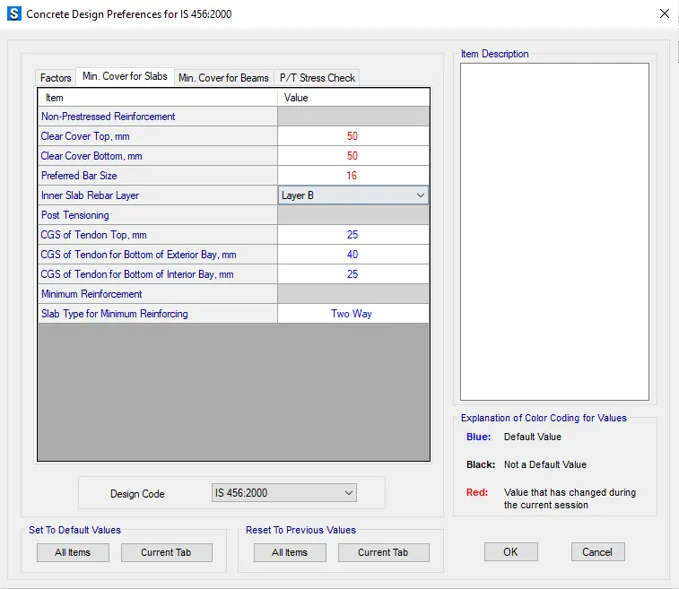
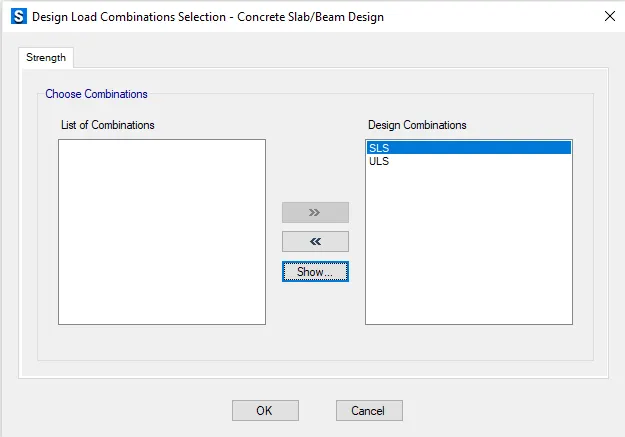
Go to Design> Concrete Slab/ Beam Design> Select design combination
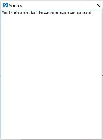
Go to Analyse> Check Model
Run Analysis and Design
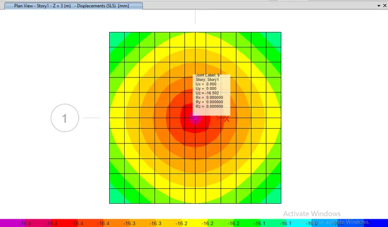
Check for Settlement
Go to Display> Show Deformed Shape
Check SLS combo
For isolated footings, maximum displacement OF 50mm is allowed as per IS 1904-1986.
The settlement, in this case, is way less than the said limit. Hence OK.
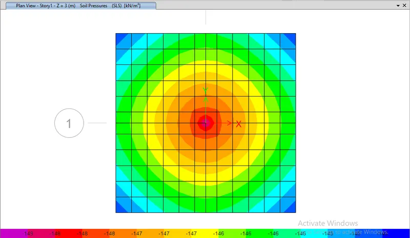
Check for Soil Pressure
Go to Display> Show Force/ Stress Diagram> Soil Pressure
Check SLS combo
The SBC of soil is 150kN/m/m2 > 149. Hence OK.
Punching Shear Check
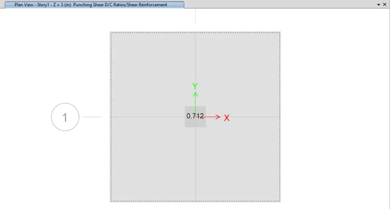
Go to Display> Show Punching Shear Design
Here it is less than 1. Hence OK.
Longitudinal Reinforcement Requirement
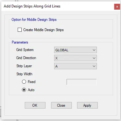
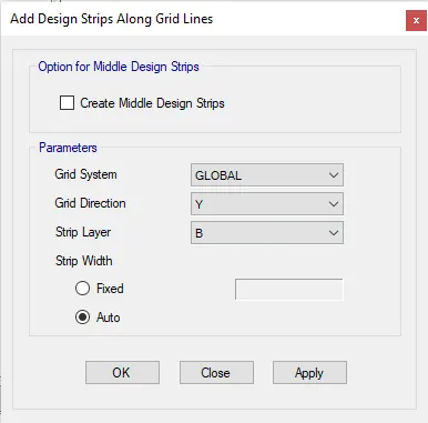
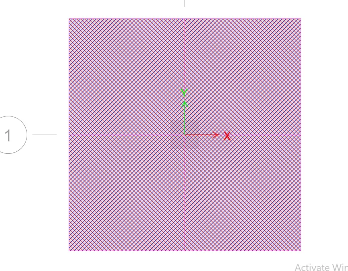
For reinforcement requirements, design strips are needed to be created
Go to Edit> Add/ Edit Design Strips> Add Design Strips Using Grids
Run analysis
Go to Display> Show Slab Design
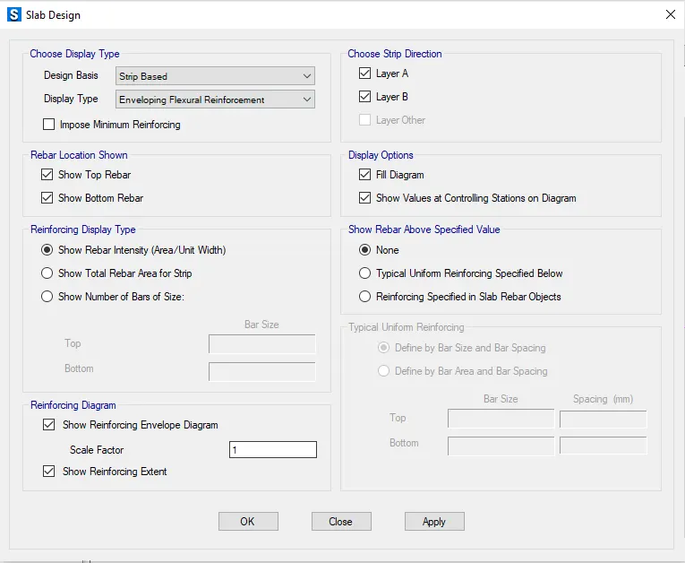
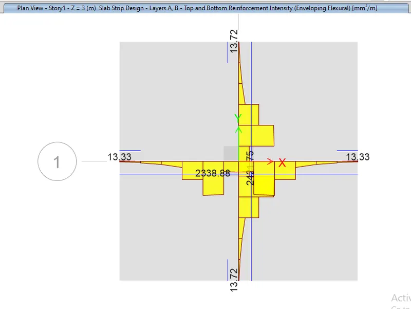
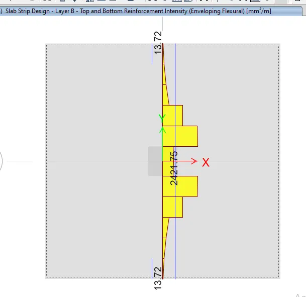
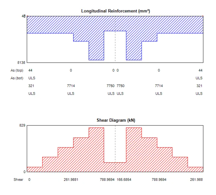
Maximum Rebar Area for the Strip A
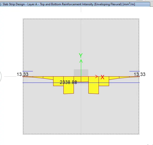
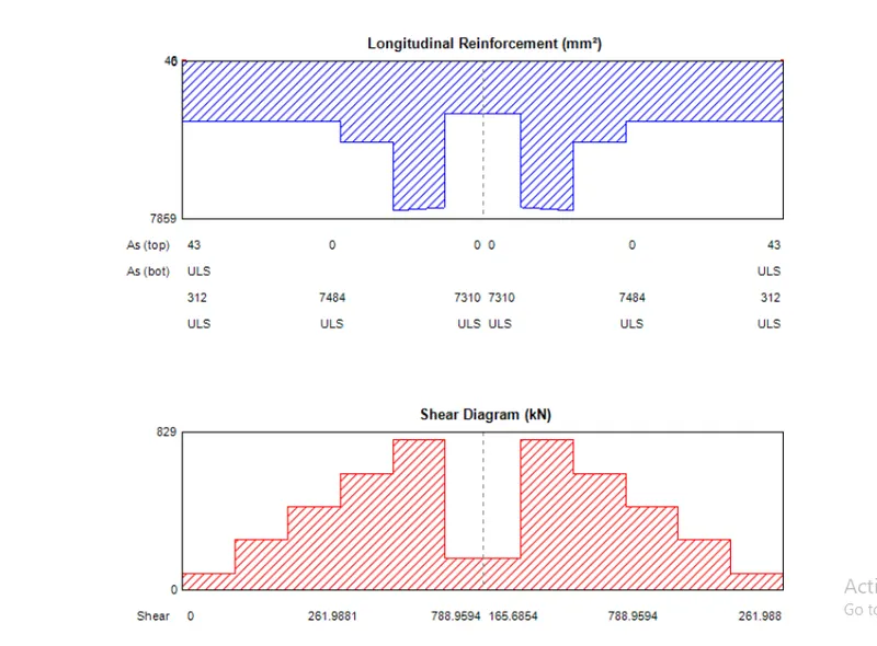
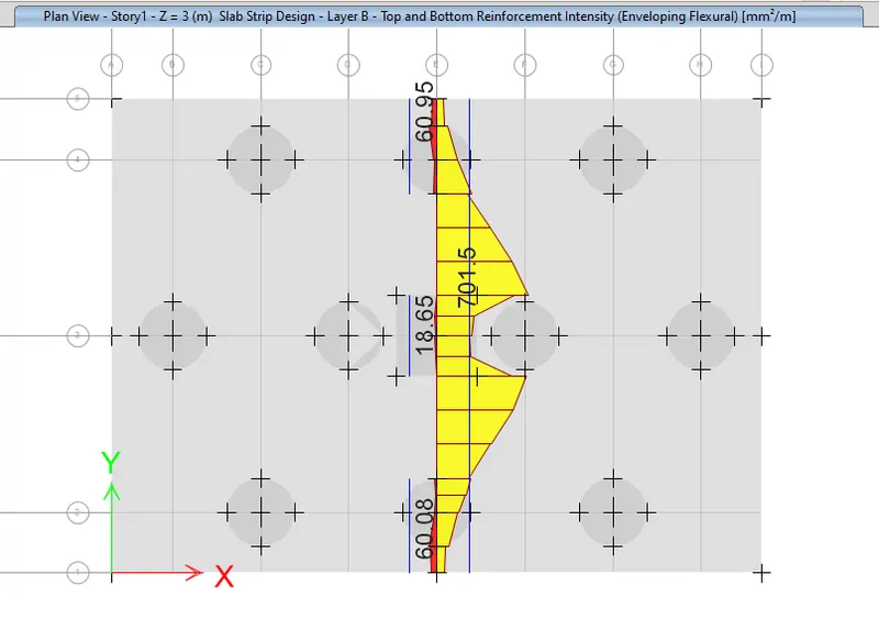
Maximum Rebar Area for the Strip B
A column of size 600x600 carrying an unfactored gravity load (DL+LL) of 1175 kN is to be supported on a pile cap, which ultimately transfers the load to the piles underneath. Piles of 16 metres in length and 500 mm in diameter are to be used. Each pile has a load carrying capacity of 200 kN. Model, analyse and design the pile cap on SAFE to evaluate the following:
· Pile group to be used
· Depth of pile cap
· Longitudinal steel on top and bottom face in both directions
Note: Participants must refer to IS 2911 (part 2) and SP 34
AIM
To model, analyse and design the pile cap on SAFE to evaluate the Pile group to be used, the Depth of the pile cap, and Longitudinal steel on the top and bottom face in both directions.
GIVEN DATA
Column size: 600 x 600 m2
Unfactored Gravity load (DL+LL): 1175 kN.
Length of the Pile: 16 m.
Diameter of the pile: 500 mm.
Pile Bearing Capacity: 200 kN.
CALCULATIONS
Number of piles
Multiply the total load with the value of 1.1 as this is the multiplier for the soil surcharge pressure
Number of Piles = 1.1 x Total load / Bearing Capacity of single pile
= 1175 x 1.1 / 200 = 6.46
Take the number of piles = 10
Spring Constant
Point spring for the piles = AE/L
Where,
A = Area = π/4 x d2 = π/4 x 5002 = 196350mm2
E = 5000 √fck = 25000 N/mm2
L = Pile Length = 16000 mm
Spring Constant = AE/L
Spring Constant = 25000 × 196350/ 16000
Spring Constant = 306796.875 N/mm
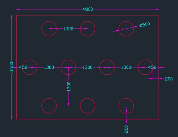
Dimension of the Pile Cap
Minimum distance between two piles is 2.5 x diameter of pile = 2.5 x 500 = 1250 mm
As the diameter of the pile is given as 500 mm
But for safe designing, we adopt 1300 mm
Now the distance from the edge of the footing to the edge of the pile = 200 mm
Based on the above calculations and the no. of piles, the size of the pile cap = 4.8 x 3.5 m2
PROCEDURE
Open SAFE
Click on the new model
Use built-in settings
Change the units and codes as per Indian standard, click OK
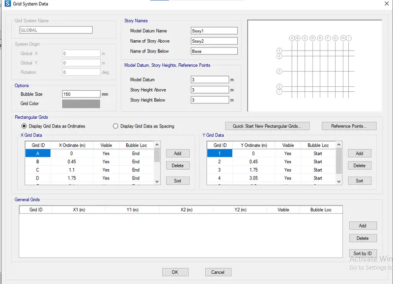
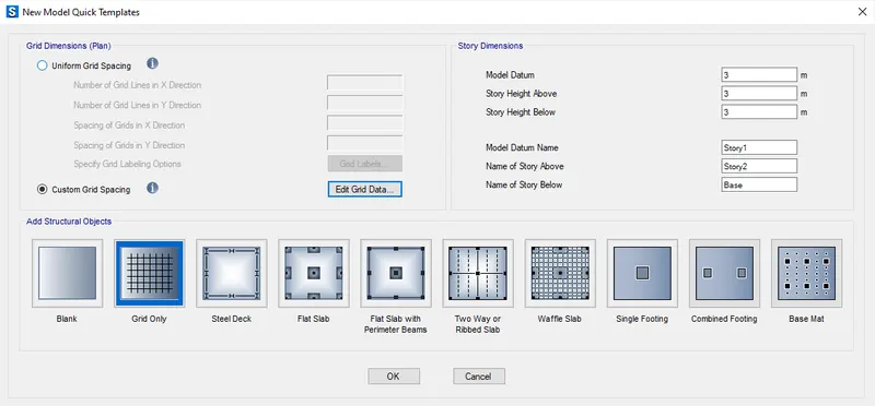
Choose Grid only, click OK
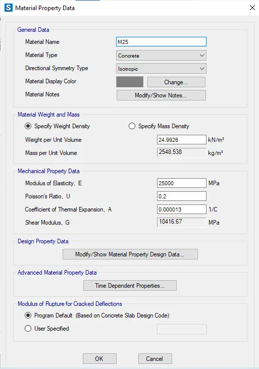
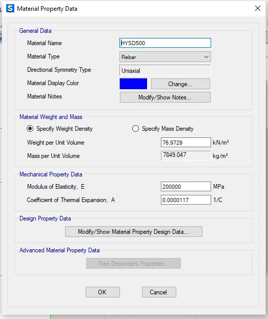
Go to Define> Material Properties> Add New Property
Add M25 grade concrete and Fe500 grade Steel Rebar
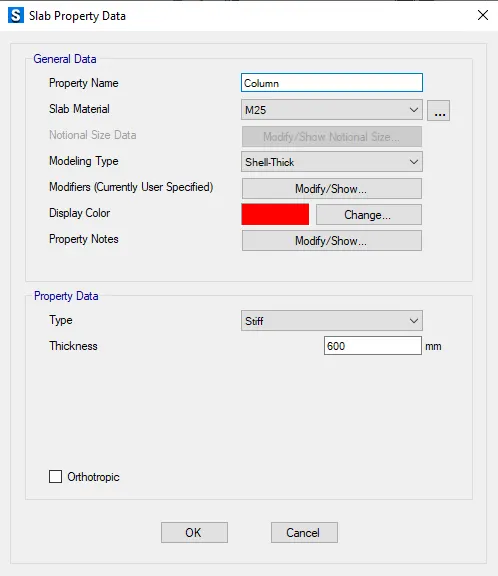
Go to Define> Section Properties> Slab Section> Add New Property
Add Pile Cap, Column and Pile500 with the following properties
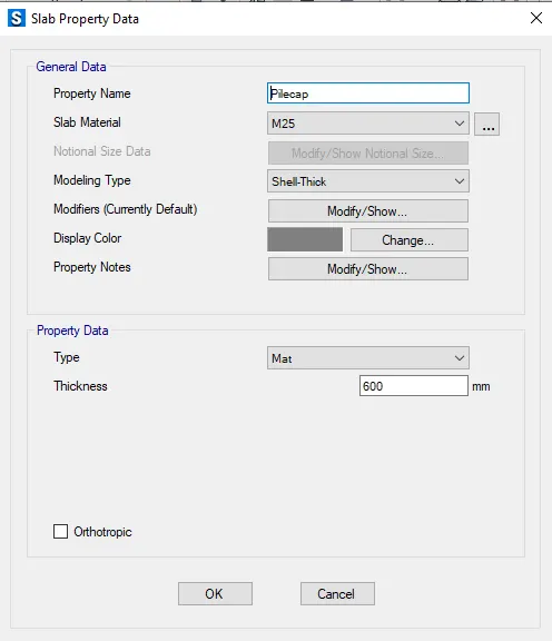
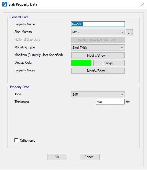
Go to Define> spring properties> Point spring> Add New Property
Add PSpr1 with the following properties
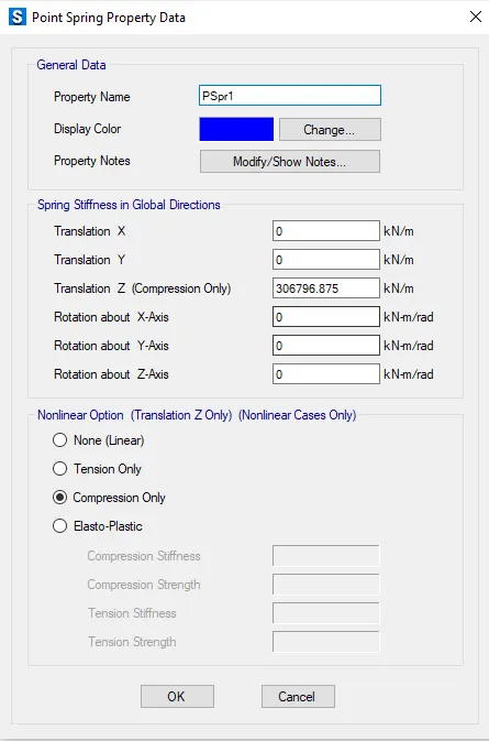
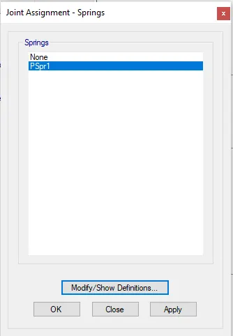
Draw a Rectangular floor with the property as “Pile cap”
Select “Quick Draw Area around point”
Draw Piles with the property as “Pile500” at each Gridpoint
Select “Quick Draw Area around point”
Draw column with the property as “Column” at the centre
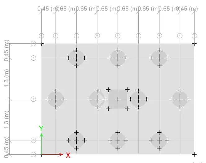
Select all joints of Pile500 and assign point spring
Go to Assign> Joint> Springs
Select the column joint
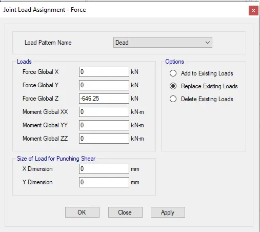
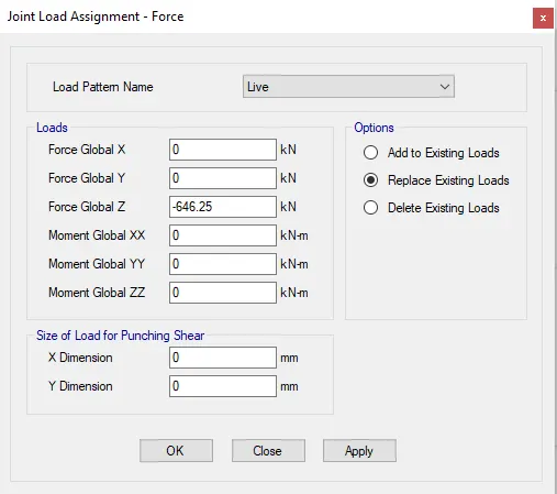
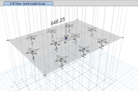
Go to Assign> Joint Loads> Force
Assign Dead load and Live load
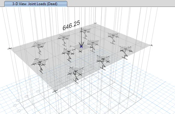
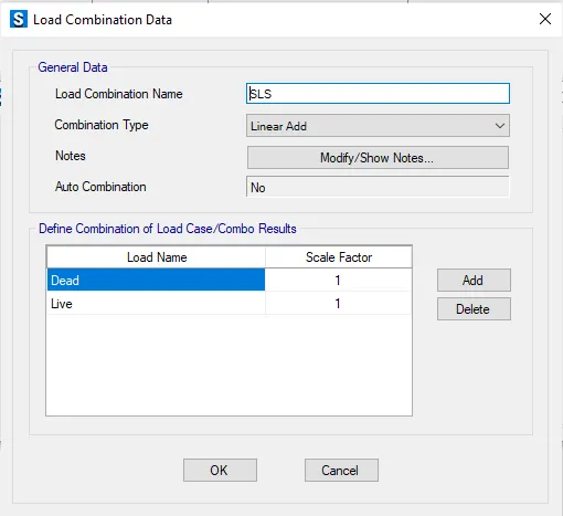
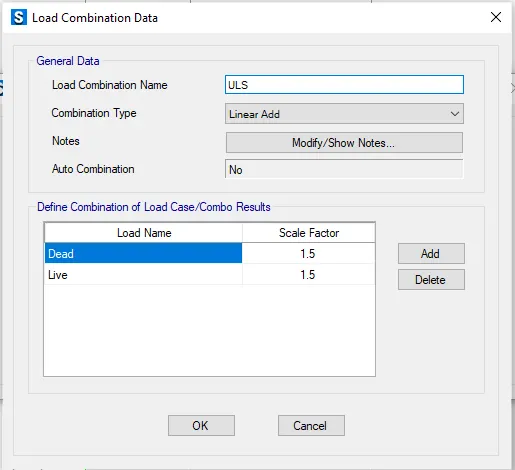
Go to Define> Load Combination> Add New Combo
Add SLS and ULS as shown below
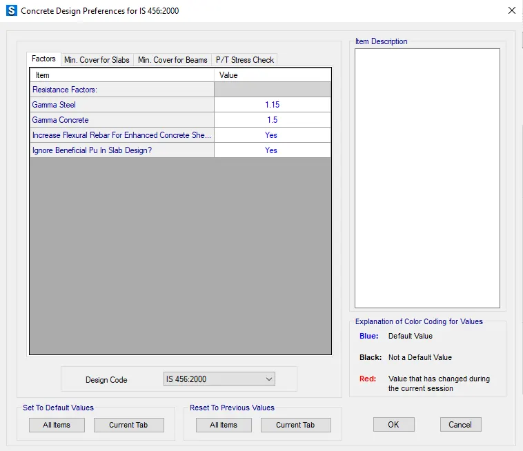
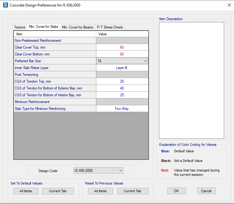
Go to Design> Concrete Slab/ Beam Design> View/ Revise Preferences
Check design preference
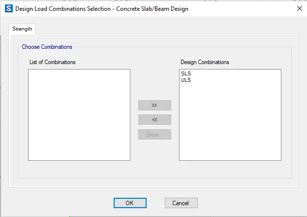
Go to Design> Concrete Slab/ Beam Design> Select design combination
Go to Analyse> Check Model
Run Analysis and Design
Check for Settlement
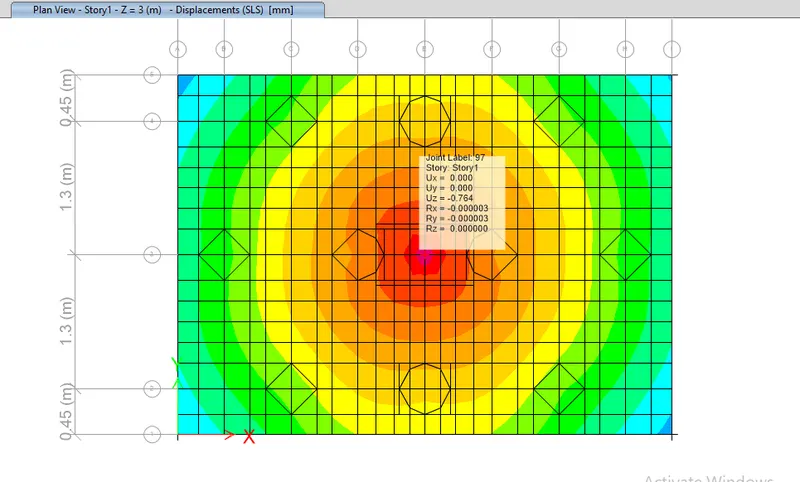
Go to Display> Show Deformed Shape
Check SLS combo
The settlement is 0.764mm is lesser than the permissible value stated by the codes (25mm). Hence OK.
Punching Shear Check
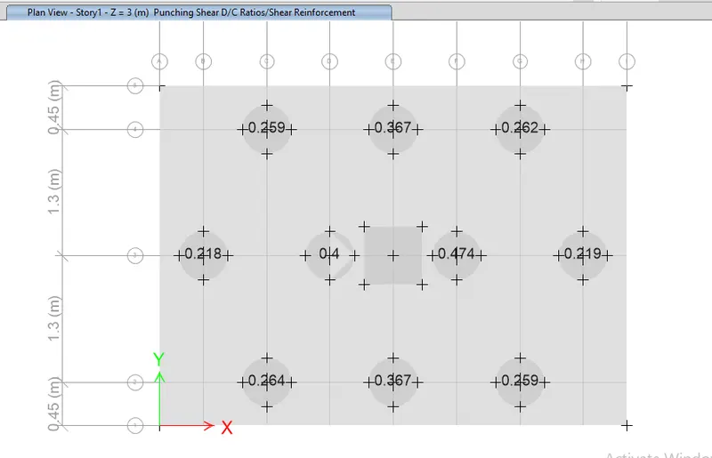
Go to Display> Show Punching Shear Design
Here it is less than 1. Hence OK.
Base Reactions at Piles
Go to Display> Show Force/ Stress Diagrams> Support/ Spring Reactions
The pile capacity is 200kN. Hence OK.
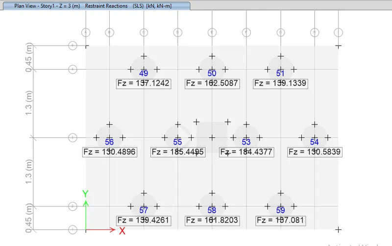
Longitudinal Reinforcement Requirement
For reinforcement requirements, design strips are needed to be created
Go to Draw> Draw design strips
Provide the design strips as shown below
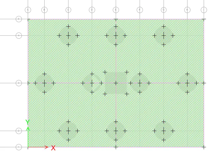
Run analysis
Go to Display> Show Slab Design
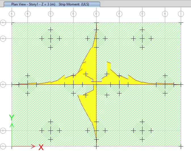
Maximum Rebar Area for the Strip A
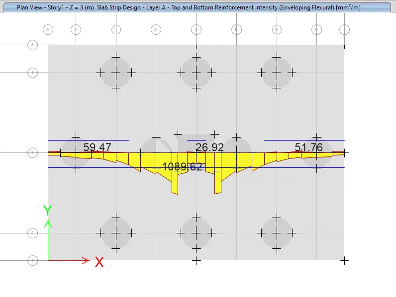
Maximum Rebar Area for the Strip B
RESULT
The design of the Pile cap foundation and isolated footing using the SAFE software is concluded.