Foundation Design using SAFE
ANS1.
AIM :-
To model the isolated footing provided in week 11 challenge on SAFE.
INTRODUCTION :-
SAFE software is a software mostly used for rapidly designing concrete floor and foundation systems. From framing layout to design and detailed drawing production, SAFE integrates every aspect of the engineering design process in one easy and intuitive environment
PROCEDURE :-
Calculations :-
Subgrade modulus = (F.O.S X S.B.C / settlement ) = (3 X 150 / 0.05) = 9000 KN/m3
Compression axial load for load calculation = (1.5 D.L + 1.5 L.L) = 2000 KN/cu.m
Unfactored load = (2000/1.5) = 1333.3 KN
Therefore, (1333.3/2) = 666.5 KN
Open SAFE and go to new model
then enter the following details attached in the screenshot for designing
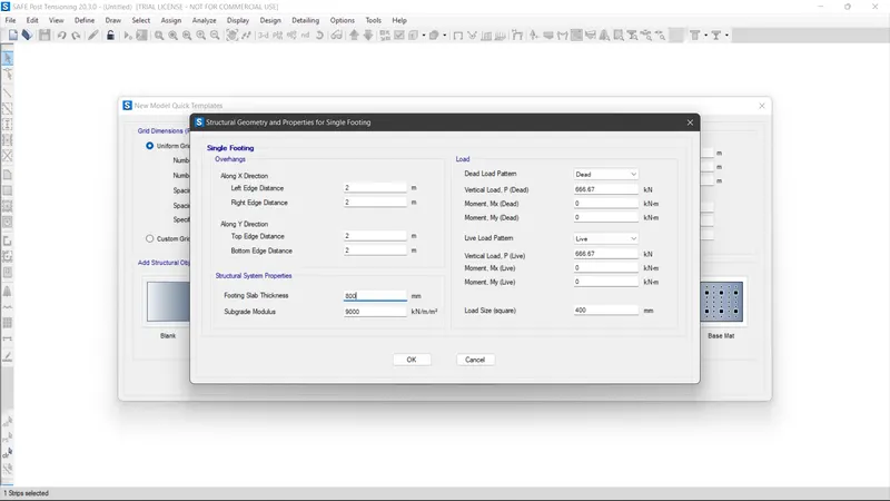
Hence , our footing has been created.
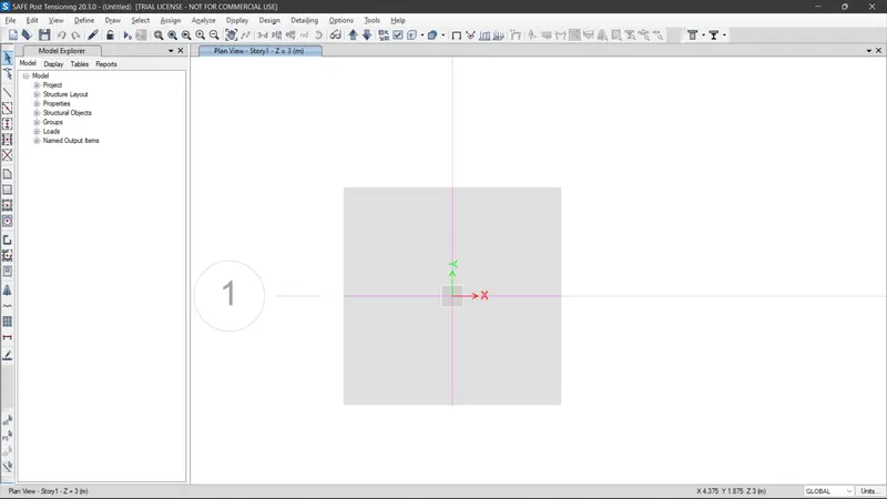
Then assign the materials
Go to Define then Material properties
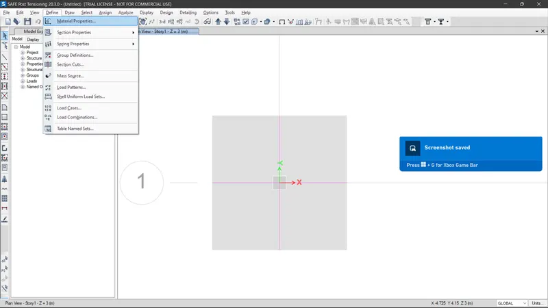
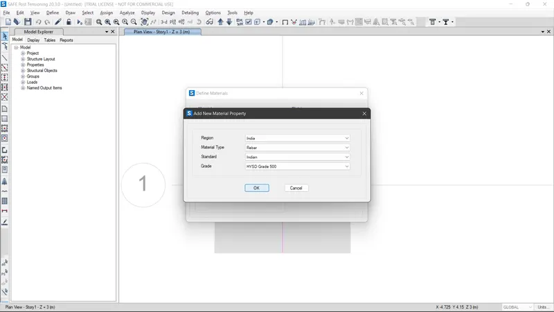
Create new property and then add the following properties of material shown below
Add M25 as concrete material type
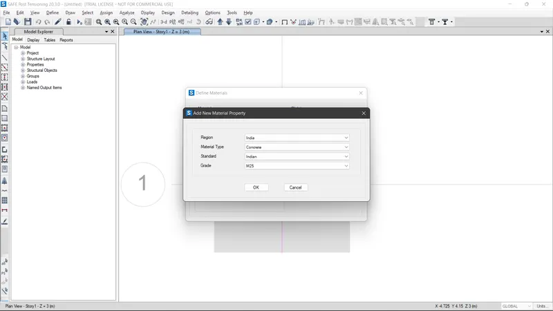
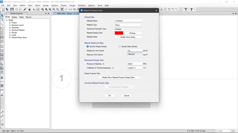
Add HYSD 500 as Rebar
Enter the weight per unit volume as 77 kn/m3
Modulus of Elasticity as 25000MPa
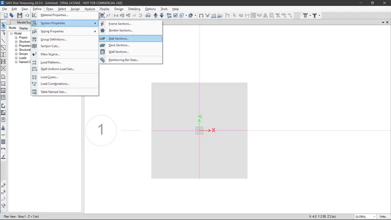
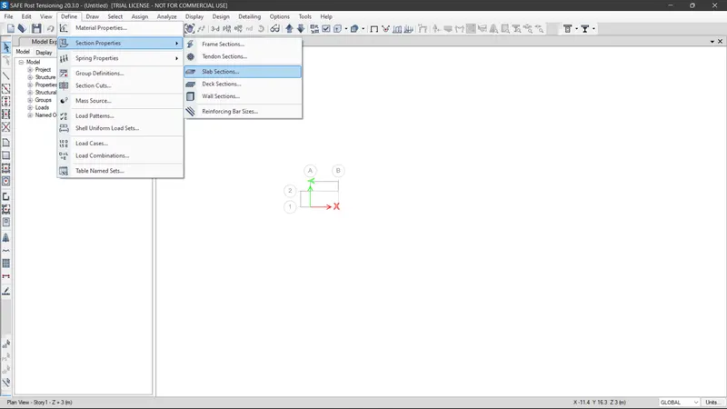
Then to assign section properties ,
GO to define then section properties then slab sections
Add the following slab sections for the model
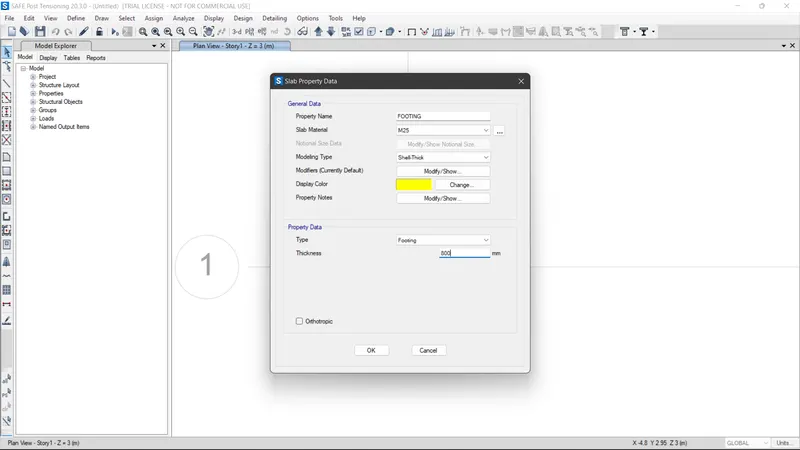
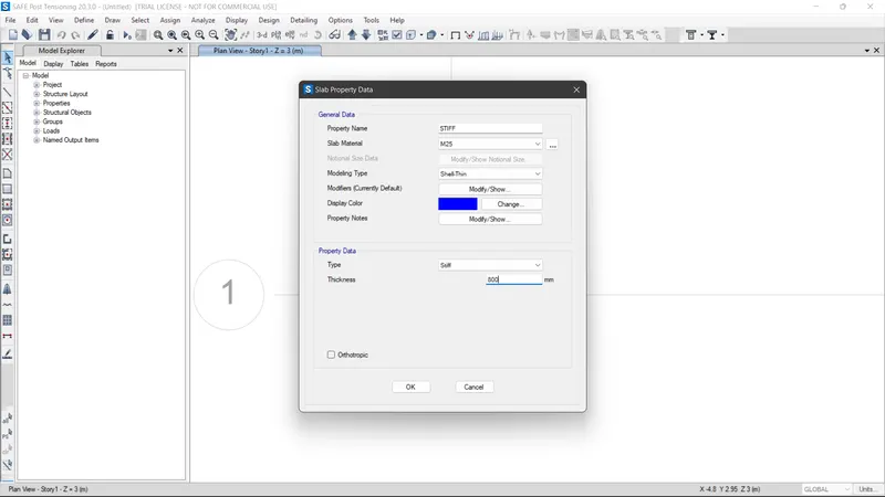
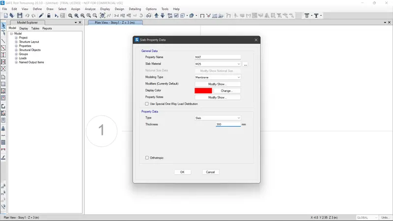
Hence the slab properties as FOORING , MAT , STIFF have been added with different assigned properties
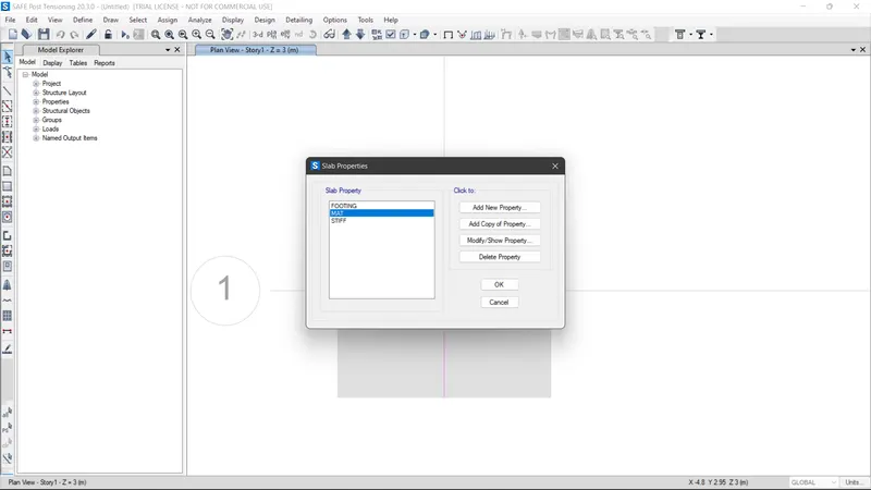
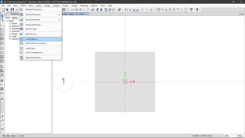
For load patterns
Go to define then click on load patterns and check that the load pattern has been assigned or not
For load combinations
Go to define then load combinations
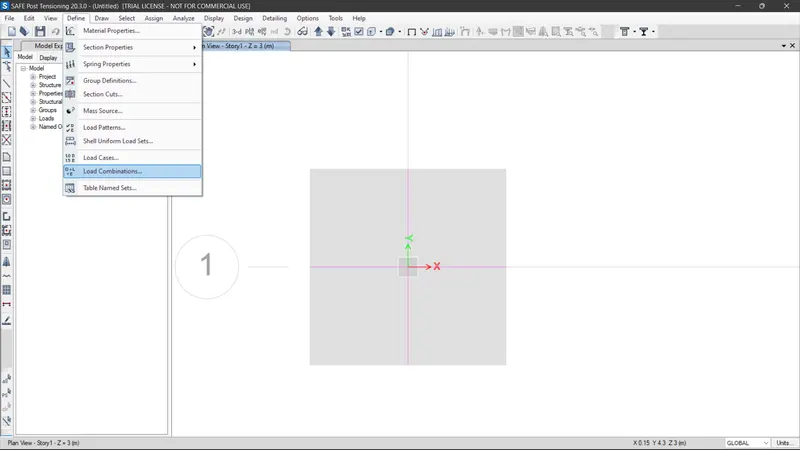
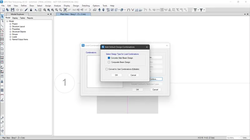
Select Default load combinations then select Concrete slab/beam design and then click ok.
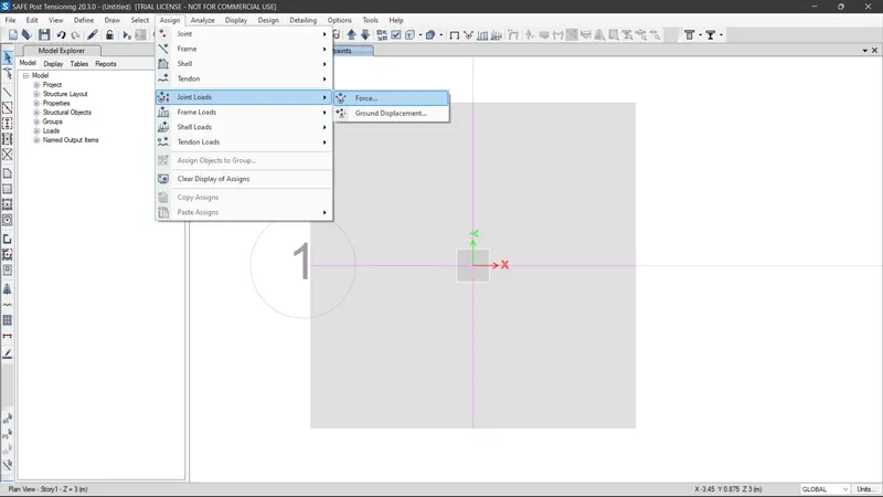
Now to assign joint loads
go to assign then joint loads then forces
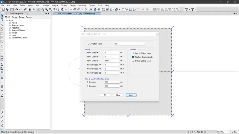
Enter the value of force as -666.67kn and select the compression only option then click apply
Now loads are visible in our model
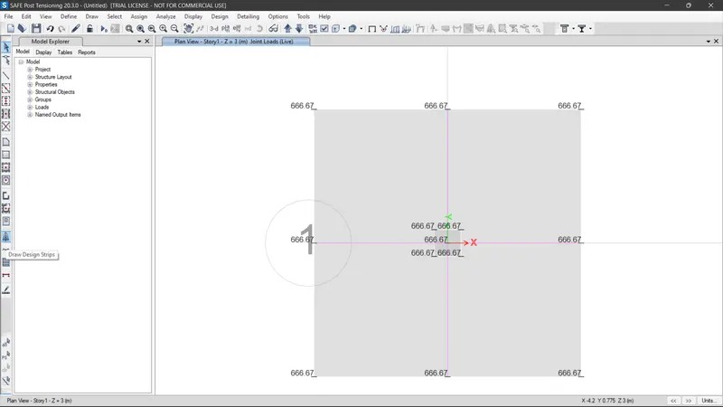
Then draw the strip lines in the both A and B directions
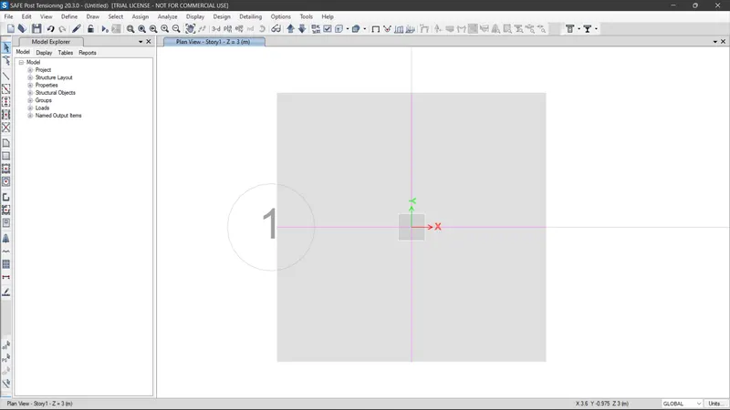
Visible design strips will look like this.
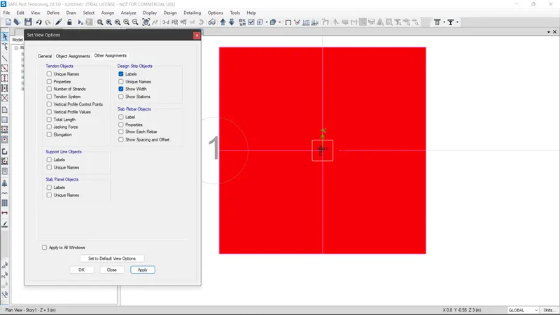
Then Run the analysis
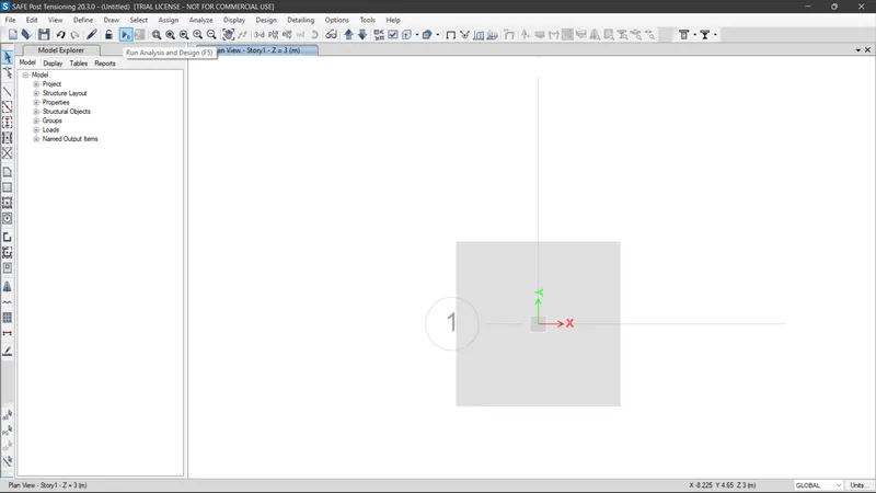
Hence analysis of the model has been completed.
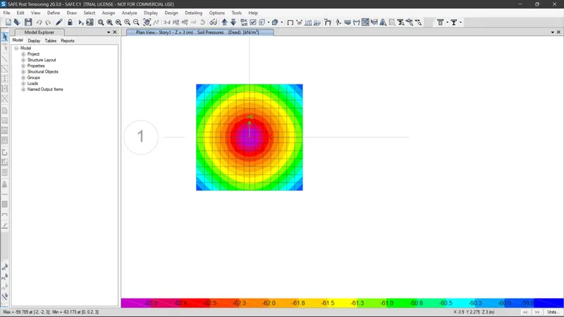
Then go to Concrete Design option and then go to start design check.
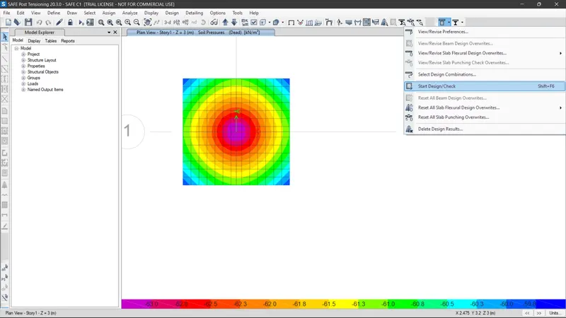
Hence design check has also been completed.
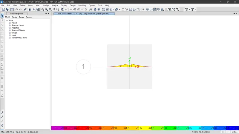
RESULT :-
Hence the model of the isolated footing provided in week 11 challenge has been successfully designed and analyzed on SAFE.
ANS.2.
AIM :-
To model, analyse and design the pile cap on SAFE and also to evaluate the following
- Pile group to be used
- Depth of pile cap
- Longitudinal steel on top and bottom face in both directions
INTRODUCTION :-
SAFE software is a software mostly used for rapidly designing concrete floor and foundation systems. From framing layout to design and detailed drawing production, SAFE integrates every aspect of the engineering design process in one easy and intuitive environment
PROCEDURE :-
a.Calculations :-
Given data,
Column of size = 600x600mm
Unfactored gravity load (DL+LL) = 1175 KN
Pile Length = 16m
Pile Diameter = 500mm
Load carrying capacity = 200 KN
Calculations
No.of pillars = (1175/200) = 5.8 = 6
Spring constant = (E X A / L)
where,
E = 25000N/sq.mm
Area (A) = ( ∏/4 ) X ( 500)2
= 196349 sq.mm
Pile length = (L) = 16000mm
So equation becomes ,
Spring constant = (E X A / L) = (26000 X 196349 / 16000) = 306795 N/mm2
Edge spacing = 200 or 300mm.
Open safe software and then go to new model
After that enter the following details which we calculated.
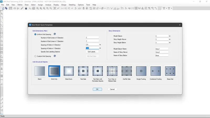
Now to define materials
Go to Define then material properties
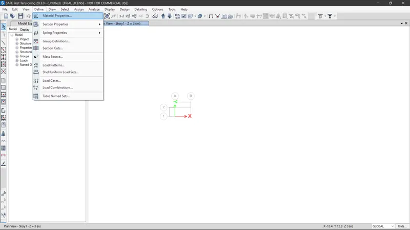
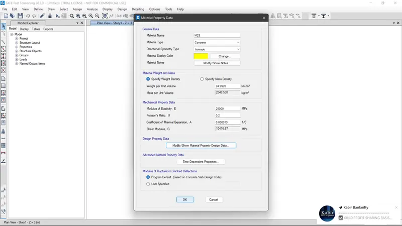
Add the materials as M25 as concrete and its properties as shown below
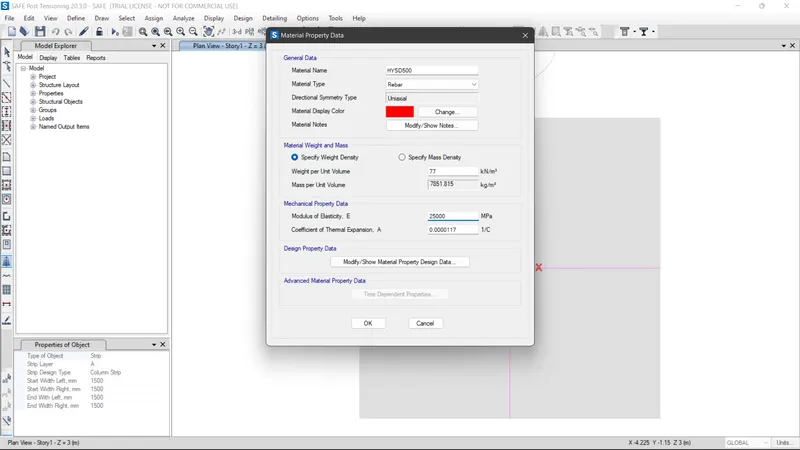
Add HYSD 500 as rebar and enter the weight per unit volume as 77kn/m3 and modulus of elasticity as 25000
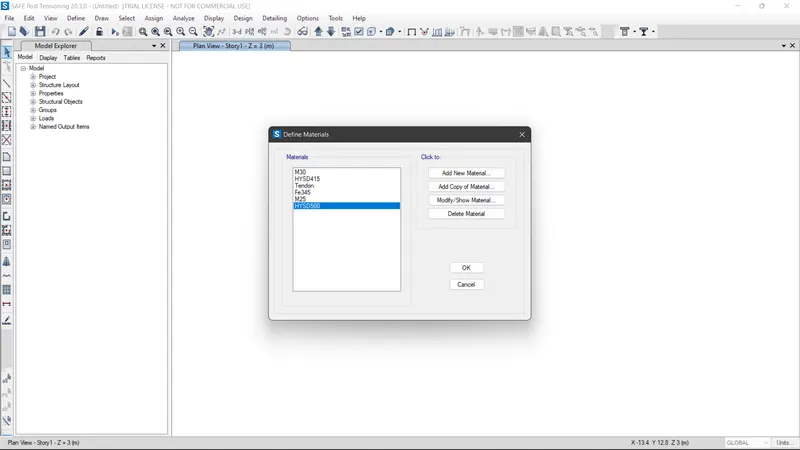
Hence added materials are now shown below
Then to add slab sections
Go to Define then section properties and then slab sections
Add PILE CAP name of property and slab material as M25 and then thickness as 800mm and type as mat

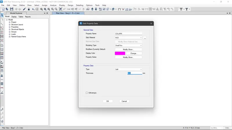
Add property as COLUMN name of Property and slab material as M25 and then thickness as 800mm and type as stiff
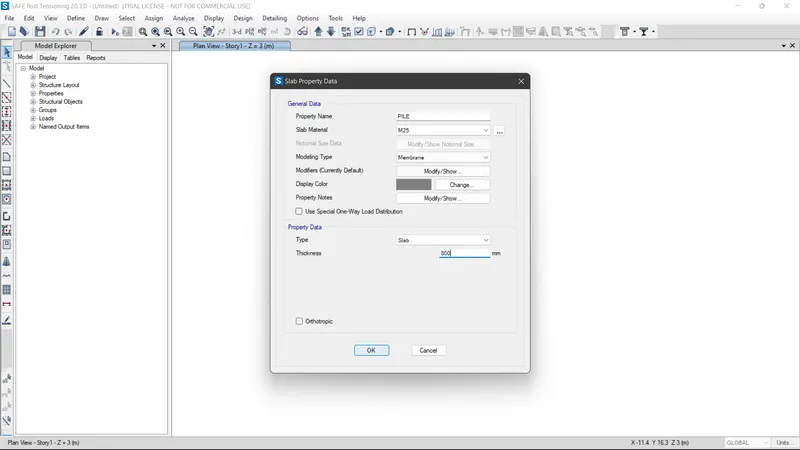
Add property as PILE name of Property and slab material as M25 and then thickness as 800mm and type as slab
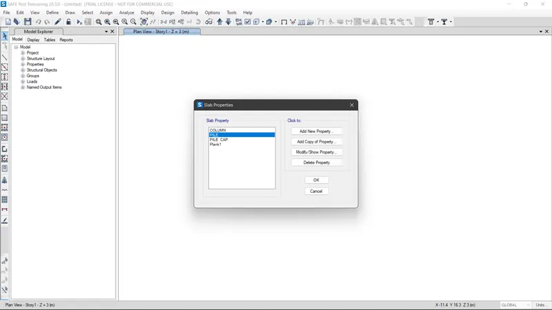
Hence defined properties are now shown below.
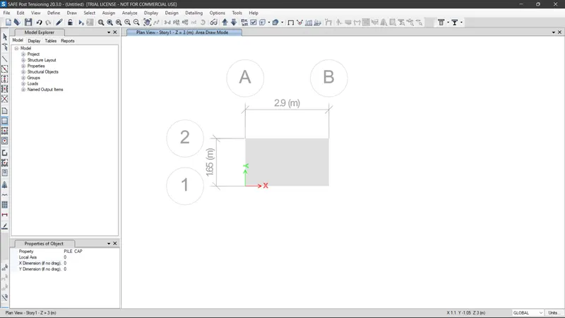
Hence model is now shown below,
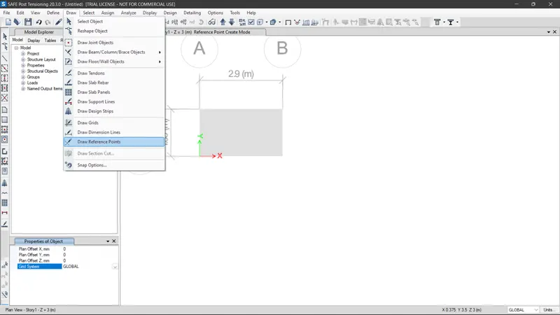
Now to draw the reference point , Go to draw then Draw reference points
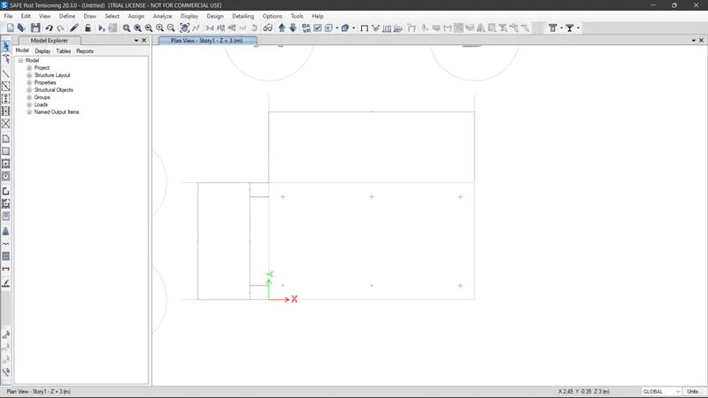
Hence now reference points are now visible.
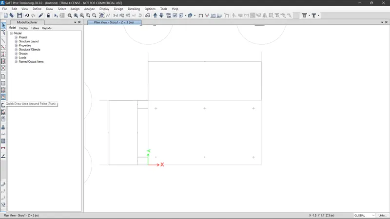
Now click on the Quick Draw Area around point tool to draw the Piles
Hence the piles caps are drawn by selecting the properties as PILE CAP
then to draw the column , select the property as COLUMN and provide the size of column as 600x600mm
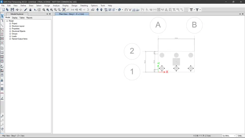
To assign the point spring loads
Go to assign then springs
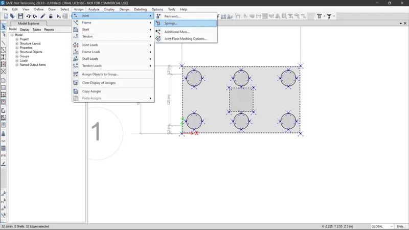
then add the point spring load and select it to assign for the model
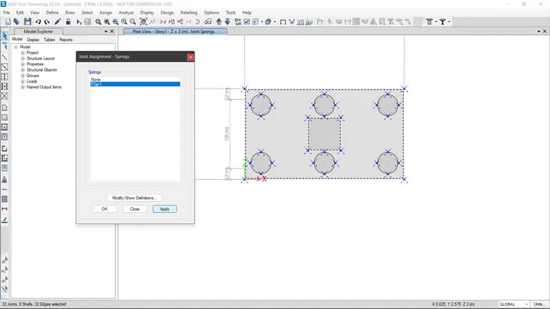
Hence the point spring loads have been assigned to the model
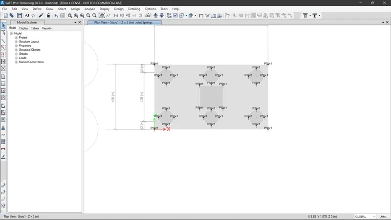
For load combination
Go to define then load combination
And then add the default design combo and select the Concrete beam design and then click ok .
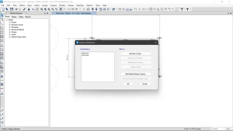
Now run the analysis
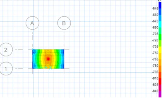
after the analysis is completed the model will look like this
here, maximum displacement obtained was 0.85
Hence safe.
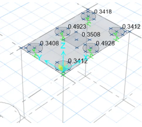
As we can see that all punching shear value are less than 1
Hence,safe.
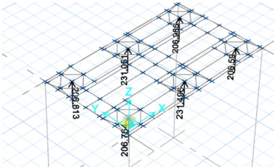
The joint reactions are also within limits
It is also safe.
To add the design strips
Go to Draw design strips option and then enter the values for Strip layer A and B
and draw Layer A first then Layer B and Run the analysis again.
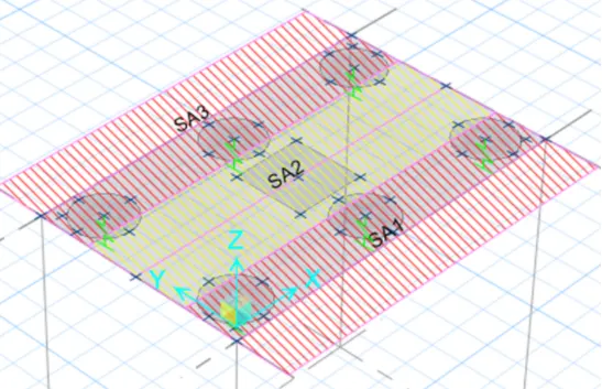
Reinforcement Slab Design :-
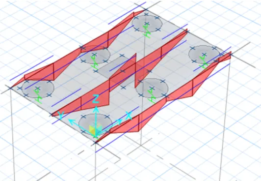
Pile cap foundation design :-
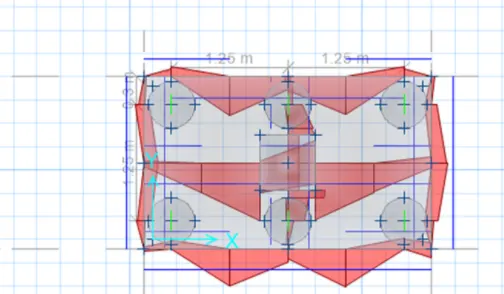
RESULT :-
Hence the model has been designed and analysed successfully using SAFE software.