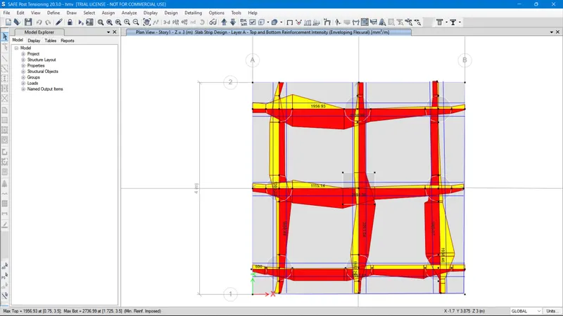
Foundation Design using SAFE
1.
INTRODUCTION :
The aim of the challenge is isolated footing design as per the manual calculation done already.
PROCEDURE:
A. ) PROCEDURE TO MODEL, ANALYSE AND DESIGN THE ISOLATED FOOTING ON SAFE :
Step 1 :
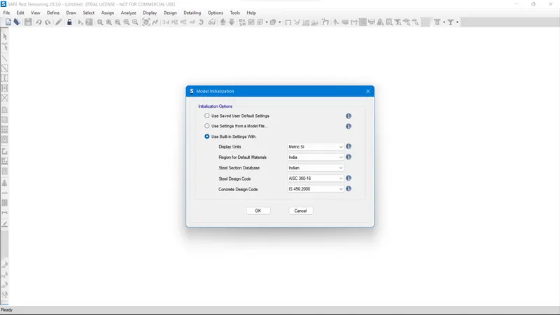
- Creating a new model
Step 2 :
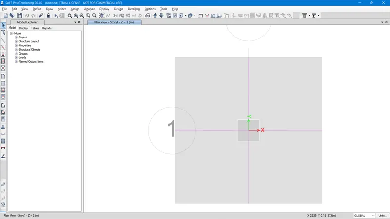
- Using the default Pre-sets window single footing is created.
- Assumed concrete footing thickness is 800mm.
Step 3:
MATERIAL DEFINITION :
Concrete property - M25 grade
Modulus of elasticity - E=25000 N/mm^2.
Rebar property - Fe500
Step 4:
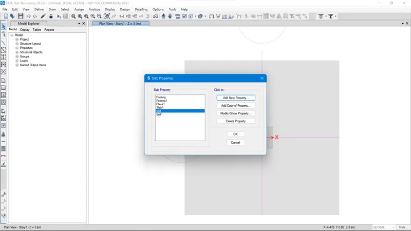
SECTIONAL PROPERTY:
- For footing slab MAT type property and 800mm thick considered.
- For stiffened member Slab stiff type property considered.
Step 5:
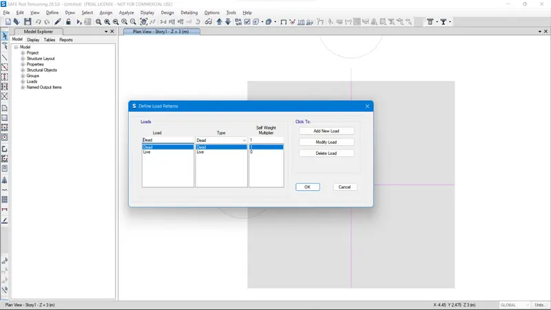
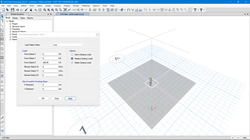
LOAD ASSIGNMENT:
- Defining Load Pattern - Dead and Live Load.
Step 6:
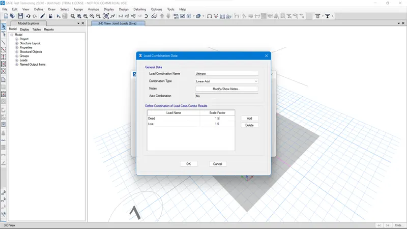
CREATE LOAD COMBINATION:
Dead - 1.5
Live - 1..5
Step 7:
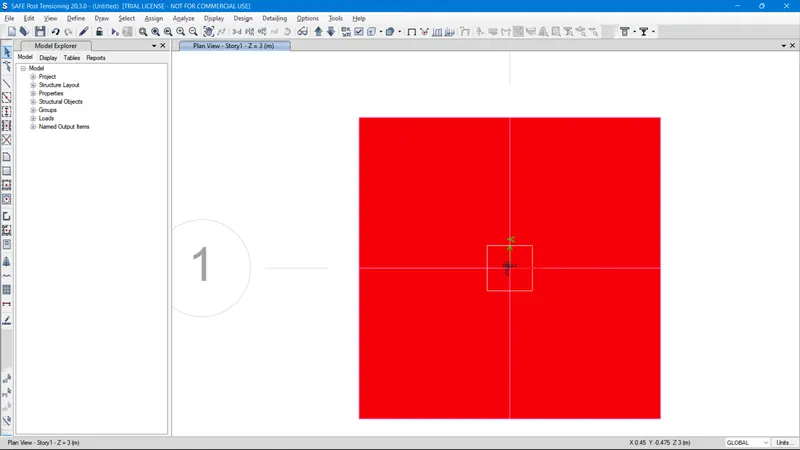
ANALYSIS :
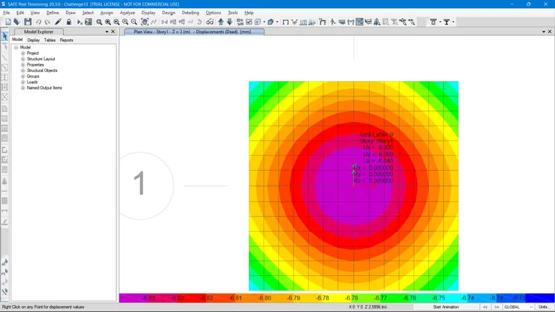
Performed Analysis
Displacement - The deflection obtained is 6mm only which is allowable minimum deflection.
Step 8:
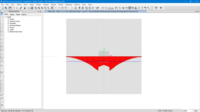
SLAB DESIGN:
- X Direction Strip (Reinforcement Required)
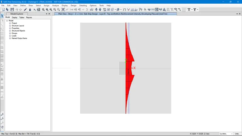
- Y Direction Strip (Reinforcement Required)
2.
INTRODUCTION :
The aim of the challenge is Pile and Pile cap design along with column as per the given values.
PROCEDURE:
B. ) PROCEDURE TO MODEL, ANALYSE AND DESIGN THE PILE CAP ON SAFE :
STEP 1 :
Creating a new model
STEP 2:
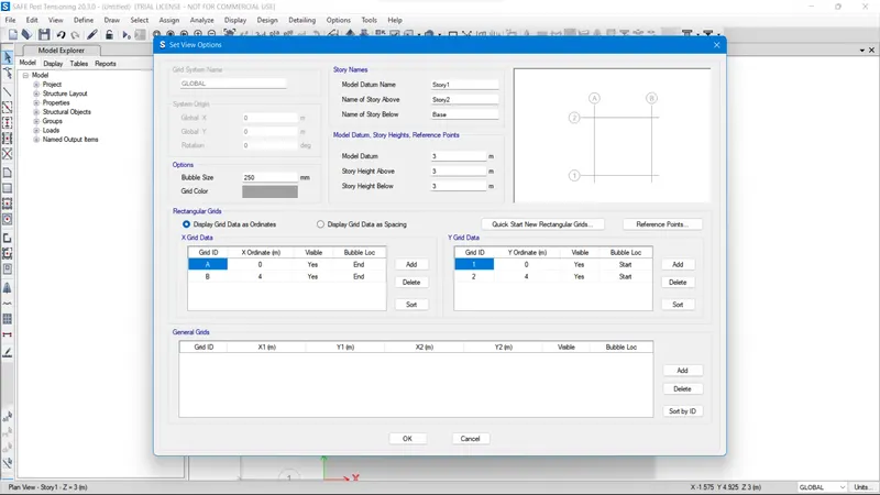
- Using the Grid tab the Pile cap slab is created.
- Given concrete pile cap slab thickness is 500mm.
STEP 3:
- The created Pile Cap slab at a size of 4mx4m in a thickness of 500mm.
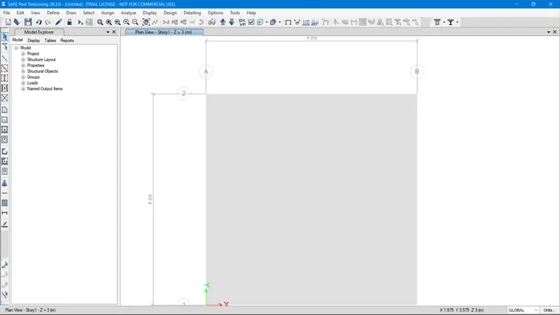
STEP 4:
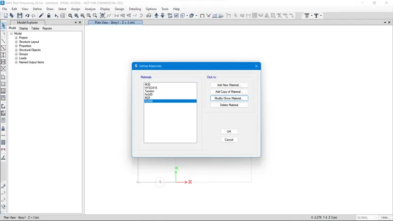
MATERIAL DEFINITION :
- Concrete property - M25 grade
- Modulus of elasticity - E=25000 N/mm^2.
- Rebar property - Fe500
STEP : 5
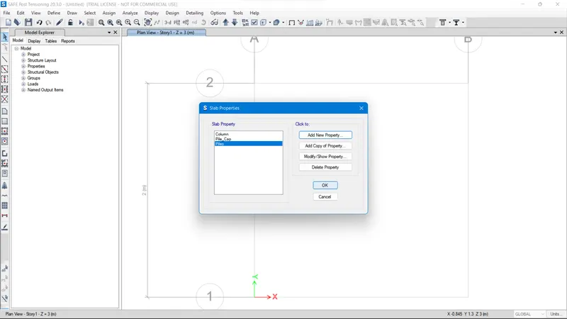
SECTIONAL PROPERTY:
- For Pile and Pile Cap type property 500mm thick considered.
- For stiffened member Slab stiff type property considered.
STEP 6:
Then the Reference points are then marked at the appropriate distances.
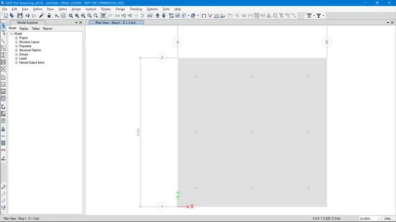
STEP : 7
- The Piles and Column slabs are drawn around the Reference points.
- The appropriate properties should be selected before applying.
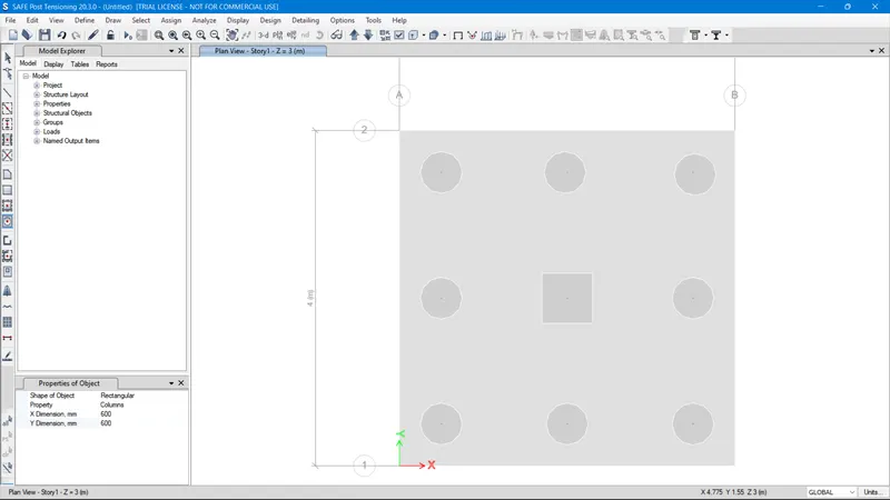
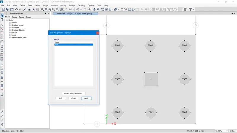
STEP : 8
- The spring load should be calculated as per the formula and apply for all the piles +z direction
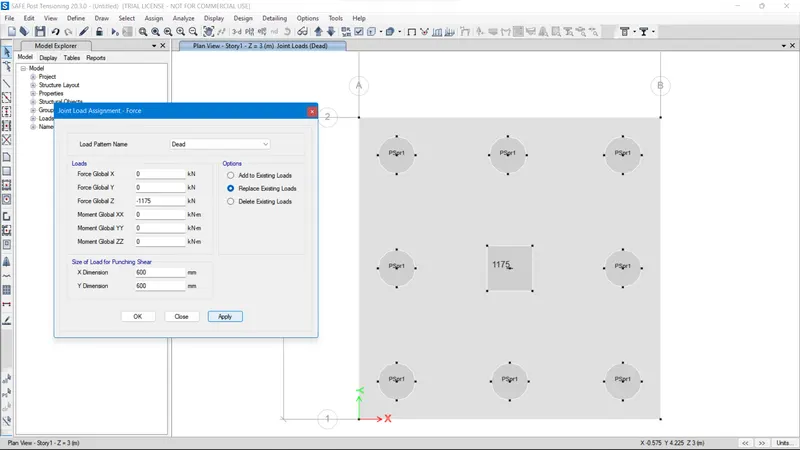
STEP : 9
- Likewise the unfactored load for the column should also be applied in -z direction.
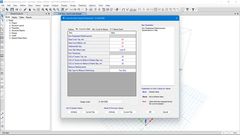
STEP 10:
- The clear cover spaces and Bar sizes should be customized in the Preference tab.
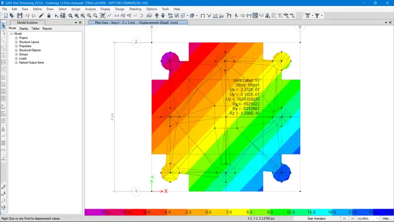
- After analysisng the Result of the Analysed Slab due to the acting load of Piles and Columns.
SLAB DESIGN:
- X Direction Strip (Reinforcement Required)
- Y Direction Strip (Reinforcement Required)