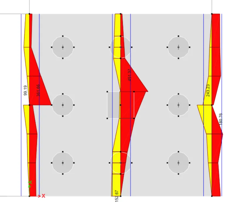
Foundation Design using SAFE
1. Model the isolated footing provided in the week 11 challenge on SAFE. Analyze and design it to verify the size, depth, and steel provided as per calculations.
2. A column of size 600x600 carrying an unfactored gravity load (DL+LL) of 1175 KN is to be supported on a pile cap, which ultimately transfers the load to the piles underneath. Piles of 16 meters in length and 500 mm in diameter are to be used. Each pile has a load-carrying capacity of 200 KN. Model, analyze and design the pile cap on SAFE to evaluate the following:
- Pile group to be used
- Depth of pile cap
- Longitudinal steel on the top and bottom face in both directions
ANSWER:
COMPLETE STEPWISE PROCEDURE TO DESIGN ISOLATED FOOTING AND PILE FOUNDATION USING SAFE
1. ISOLATED FOOTING:
- Initial Design Setup
- Download the SAFE software from the official CSI website, to begin with, the project.
- Locate the software in your machine at the desired disk.
- Then, open the software after installing it.
- Then, you will find a similar user interface as included in ETABS.
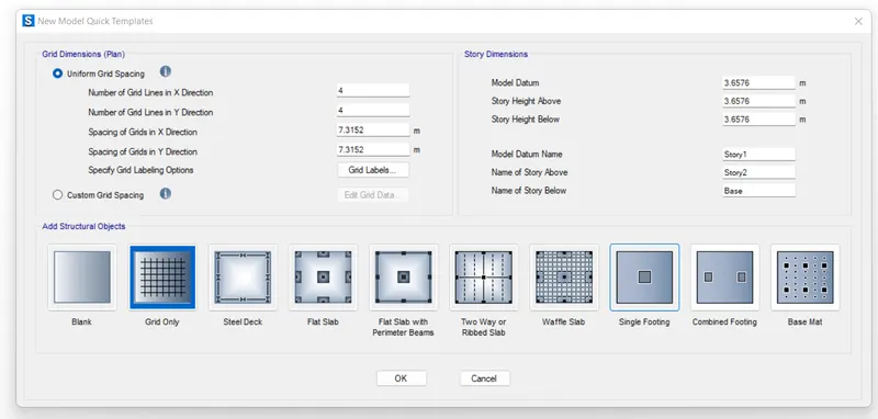
- So, click on the new model option as we do while designing in ETABS.
- Then, there will be a few footing templates made available to you by the software.
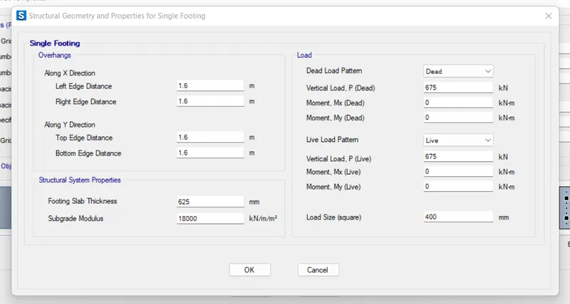
- So, choose the isolated footing option from the list and feed the footing details.
- In the detail section, you need to insert the length, breadth, and depth of footing.
- At the same time, you can also define the load type and intensity in the same section.
- It saves you time from having to apply load manually after modeling.
- Define Material Properties
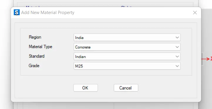
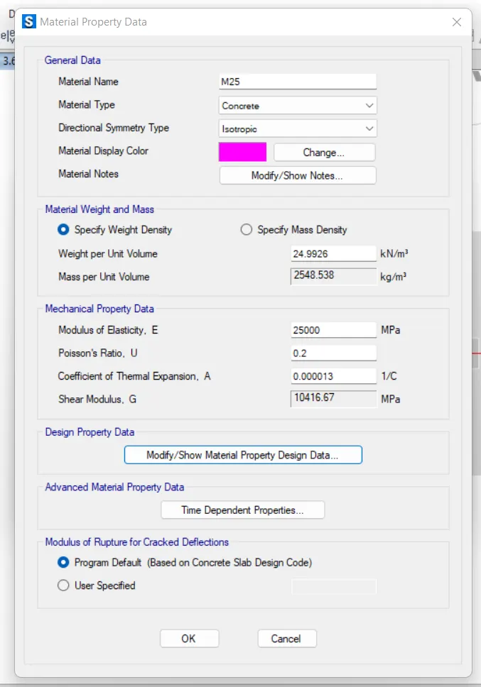
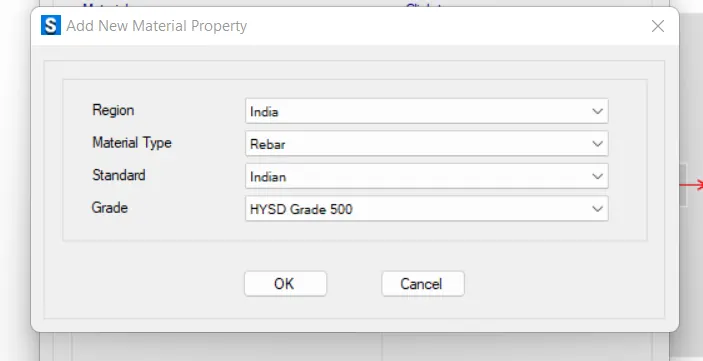
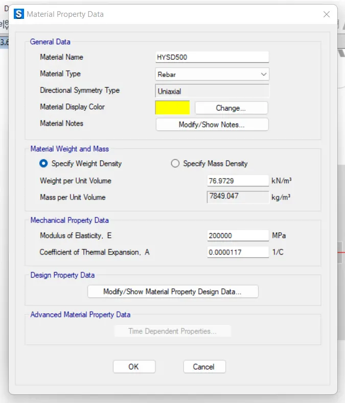
- Like we did in ETABS, we need to define the material properties in an exact manner.
- However, we don't need to have shear ties for footings. So, don't define fe415. Just define concrete and fe500 and that's it.
- The same is shown below:
M25
FE 500
- Define Section Properties
- This can also be done the same way as ETABS.
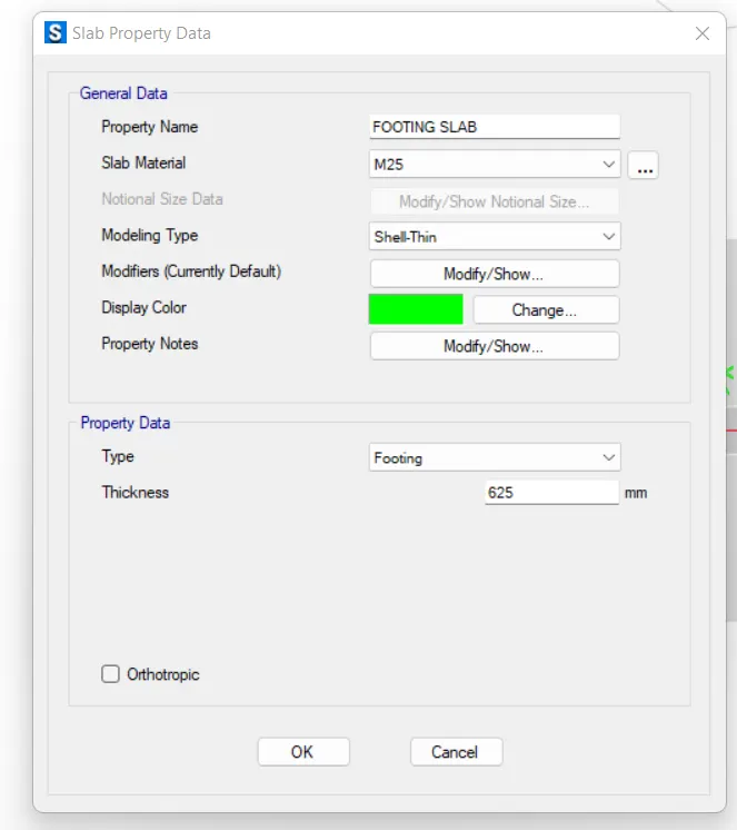
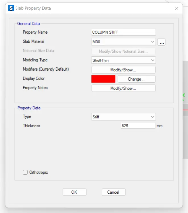
- But here, we need to define two different types of slabs. One is the footing slab and the other is the stiff slab for the column area over the footing.
- However, the depth of both the slabs shall remain the same as calculated from the pressure formula.
- Also, make sure to select the property type as footing and stiff respectively while defining the slabs.
Footing Slab
Stiff Slab (for the column portion)
- Define the Load Combinations
- The procedure is exactly the same as we do in ETABS.
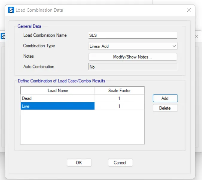
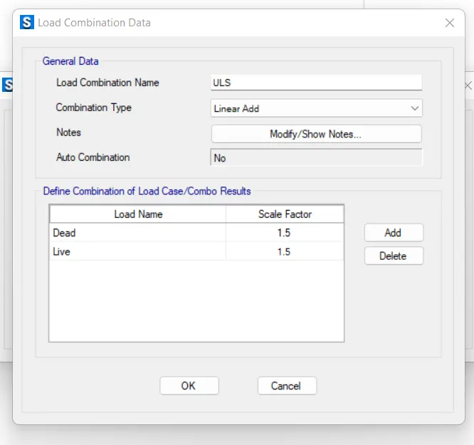
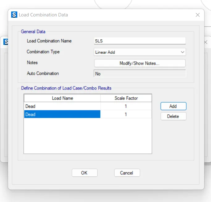
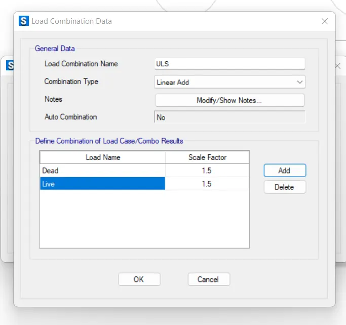
- However, we need to define two types of load combos for footing that are service load and ultimate load combinations.
- In the service load combination (SLS) total unfactored column load will be accounted for.
- Whereas in the case of ULS, a factor of 1.5 shall be multiplied by the dead and live loads.
- So, the same is done as follows:
SLS Load Combo
ULS Load Combo
- Load Assignments
- We have already assigned loads while defining the footing section in the beginning.
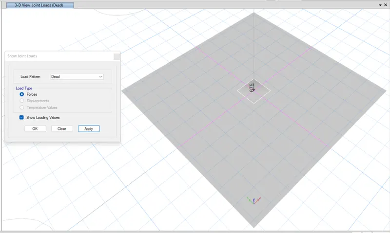
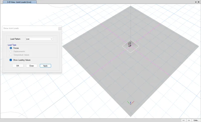
- However, we need to check if the loads are appropriately located or not.
- And for this, go to display>show loads assigned>dead/live>ok.
Dead Load
Live Load
- Define and Assign Soil Spring
- Spring constant for soil is given by the formula: Factor of safety x soil bearing capacity / allowable settlement.
- So, calculate the same based on your soil report then define the same from define>soil properties.
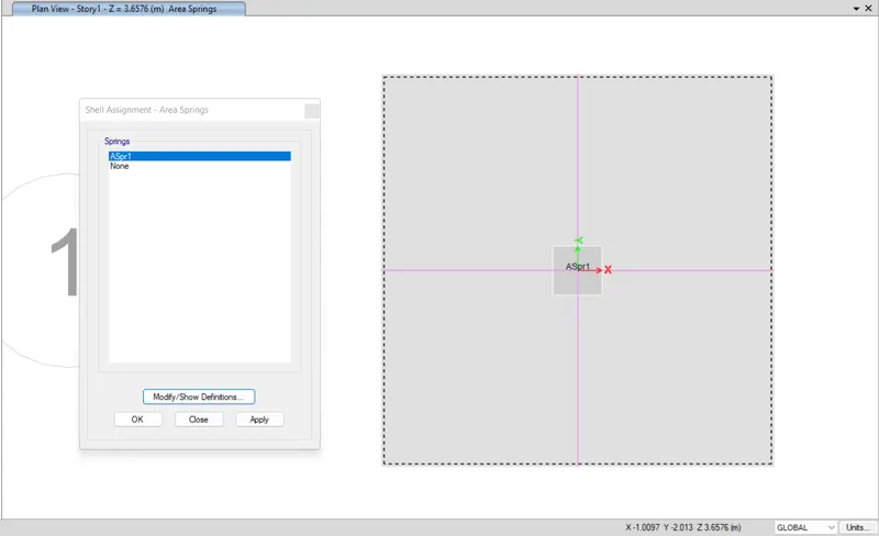
- Then, select the footing>go to assign>area spring>spring1>ok.
- The procedure for the same is shown below:
- Run the Analysis and Design
- After assigning the load patterns and the soil spring, our model is set to be run for analysis.
- Also, unlike ETABS, safe runs the analysis and designs the section for you at the same time.
- However, there are a few checks you need to make once the analysis and design are completed and the same is discussed in the below sections.
- Check for Settlement
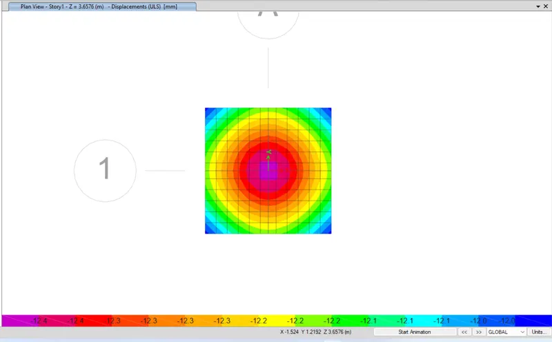
- The first thing we need to observe is the total footing slab settlement measured in mm.
- And to do so, go to display>show deformed shape>SLS load combo>ok.
- SAFE will show you the total displacement in mm due to the said load combination.
- And it should be within the limits specified by the codes.
- So, for isolated footings, 25mm of maximum displacement is allowed as per the codebook.
- And the settlement in case of our footing is inserted below that is way less than the said limit. Hence OK.
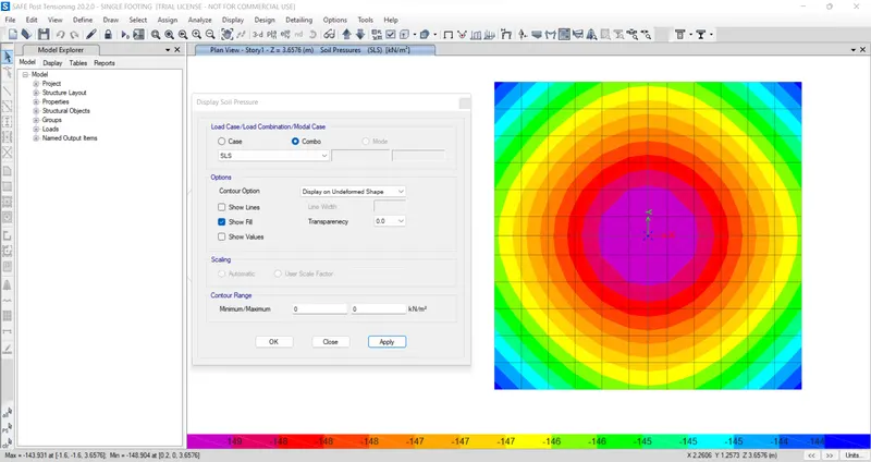
- Check for Soil Pressure
- Now we need to see if the soil pressure due to the service load combination is within the range of soil bearing capacity as received from the soil report.
- And to do that, go to display>soil pressure>SLS load combo>ok.
- The same is shown below which in our case is 149 KN/sq.m < 150KN/sq.m. Hence OK.
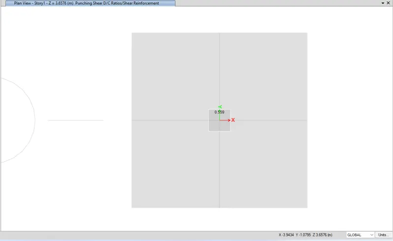
- Punching Shear Check
- Same as before, go to display>punching shear>ULS load combo>OK.
- SAFE will display the demand/capacity ratio which must be less than 1 for each joint.
- So, in our case, it is way less than 1. Hence OK.
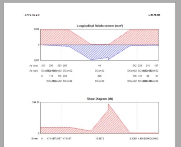
- Longitudinal Reinforcement Requirement
- Now that our footing section has passed all checks, we can look at the reinforcement requirements given by SAFE.
- However, we need to add the design strips while modeling the footing before running the analysis.
- Design strips can be automatically added by going to edit>add design strip>automatic.
- There are two layers of strips A and B running in X and Y directions respectively.
- So, SAFE will show the rebar requirements based on those strips.
- So, once the checks are done. Go to display>show slab design>OK.
- Rebar requirement for each strip shall be visible on your SAFE screen.
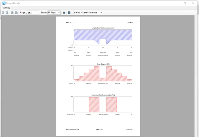
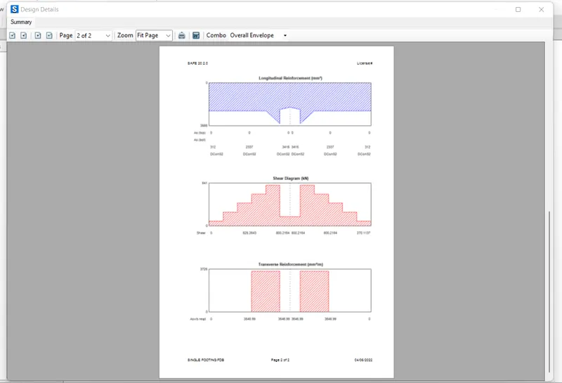
- And when you right-click on the joint of each strip, you can see the details and the maximum rebar area calculated by the software which is shown as follows:
Maximum Rebar Area for the Strip A
Maximum Rebar Area for the Strip B
2. DESIGN OF PILE FOUNDATION
- Hand Calculations
We will always be provided with several data regarding the pile foundation from the soil report, we just need to do some calculations to arrive at the number of piles needed for our foundation.
Given Data:
Column size: 600 x 600 sq.m
Unfactored Gravity load = 1175 KN
Length of the pile to be used = 16 meters
Diameter of one pile = 500 mm
Pile Bearing Capacity = 200KN
- Calculate the number of piles required:
No. of piles required = total load / Bearing Capacity of single pile = 1175 x 1.1 / 200 = 6.46 = 8 nos.
... (1.1 multiplier for soil surchage pressure)
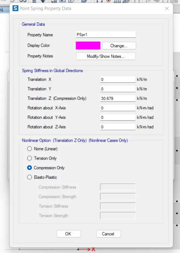
- Obtain the Spring Constant:
Point spring for piles is given by: AE/L = 306796.15 N/mm
- Length of the pile:
Minimum c/c distance between two piles as per the code = 2.5 x pile dia = 2.5 x 500 = 1250mm
However, we have adopted 1300mm for a safer design.
distance from the edge of footing to the edge of pile = 1 x pile dia = 1 x 500 = 500mm
So, based on the above calculations and the number of piles required, we have opted for 4.1 x 4.1 sq.m footing.
The same is modeled using SAFE as shown below in a stepwise manner.
- Grid Setup
- Open a new model and instead of choosing from the footing templates provided by SAFE, select the only grids option and click on the custom grid option.
- Then, based on the hand calculations, define the grid pattern and the distance as shown below:
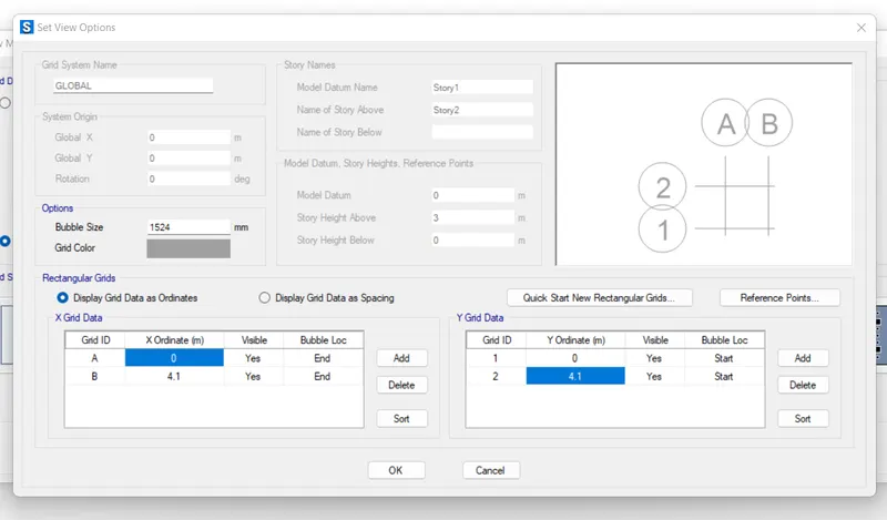
- Define Materials and Sections
- The process of defining the materials and sections is fairly the same.
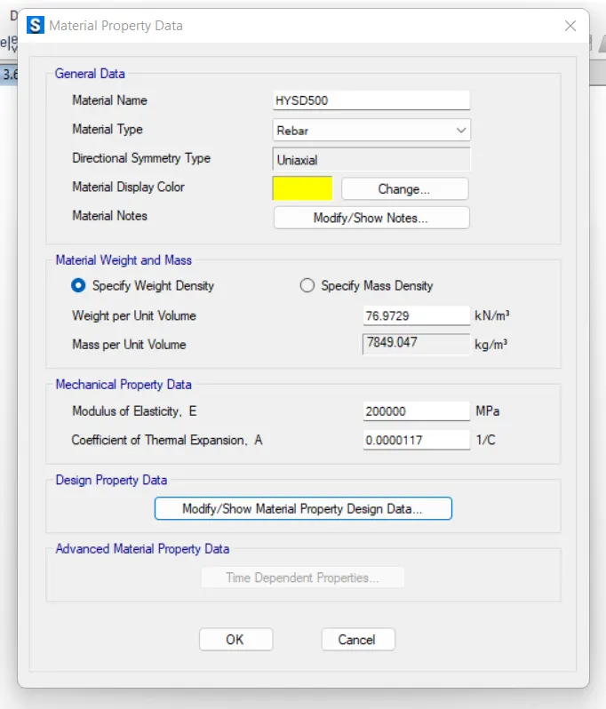
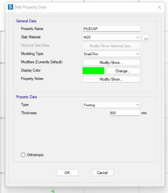
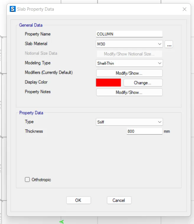
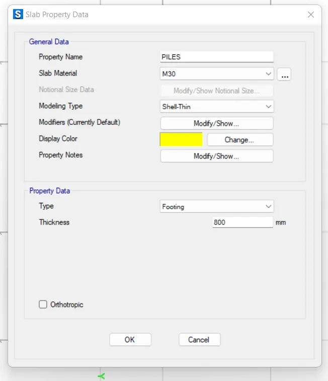
- So, we won't delve deep into it and all the defined properties are directly inserted below:
M25 Concrete
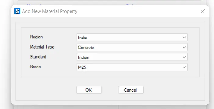
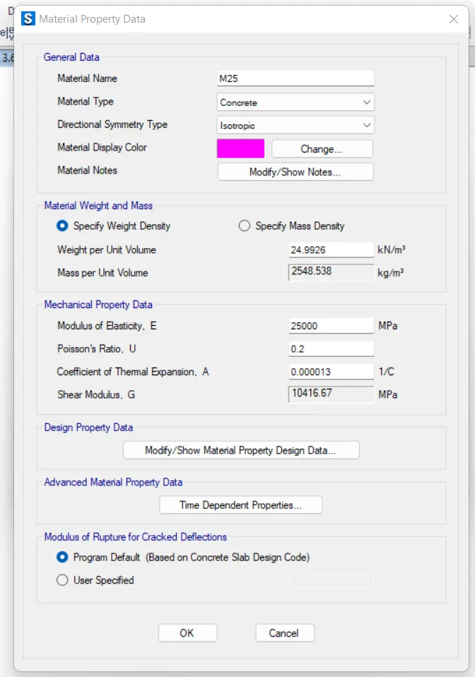
FE500
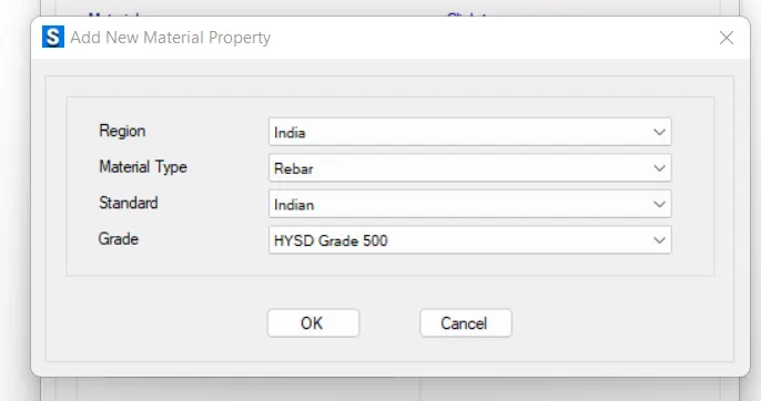
PILE CAP
COLUMN STIFF
CIRCULAR PILES
- Draw the Pile Section
- After defining the properties, we need to draw the entire pile foundation.
- The pile cap can be drawn easily as a rectangular slab running from one end of the grid to the other.
- However, to draw the stiff columns and the circular piles, we need to first draw the reference points.
- And then we need to model piles and the stiff slab around the same reference points.
- So, go to draw>reference points>specify offset>locate the points.
- Then, click on the draw floors around point option>specify the shape>dimensions>click on the points>the section is ready.
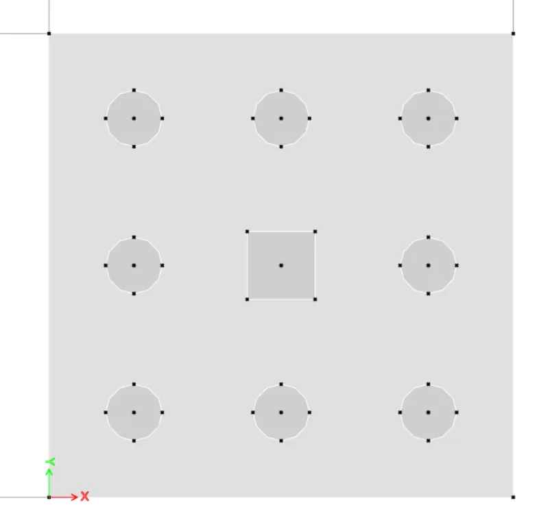
NOTE: We need to add dummy joints at the center of all piles and the column by using the draw joints option.
- Define and Assign the Point Spring
- As you know we have calculated the spring constant while doing the manual calculations.
- So, we just need to enter the calculated value into the software.
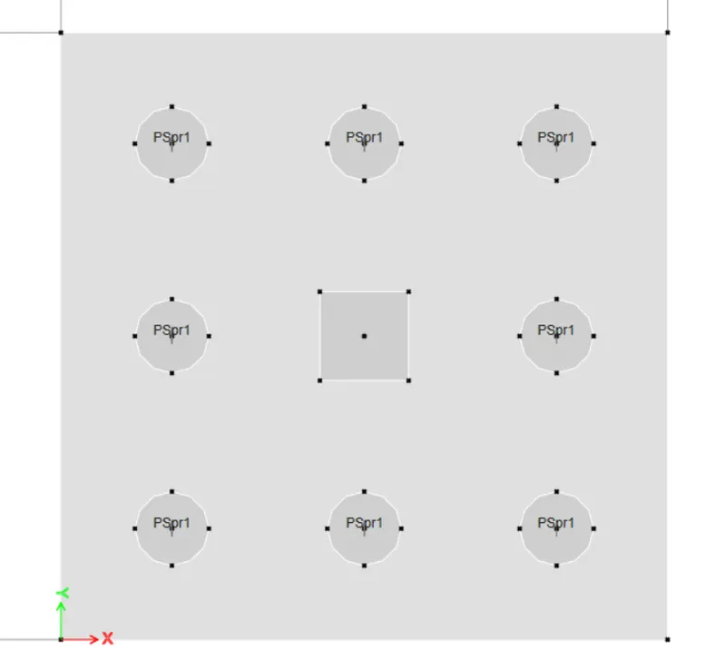
- And to do that go to define>spring>point spring>add new>feed the spring constant value>check compression only>hit OK.
- Now, select the central joints of all the piles>go to assign>joint>point spring>Pspr1>OK.
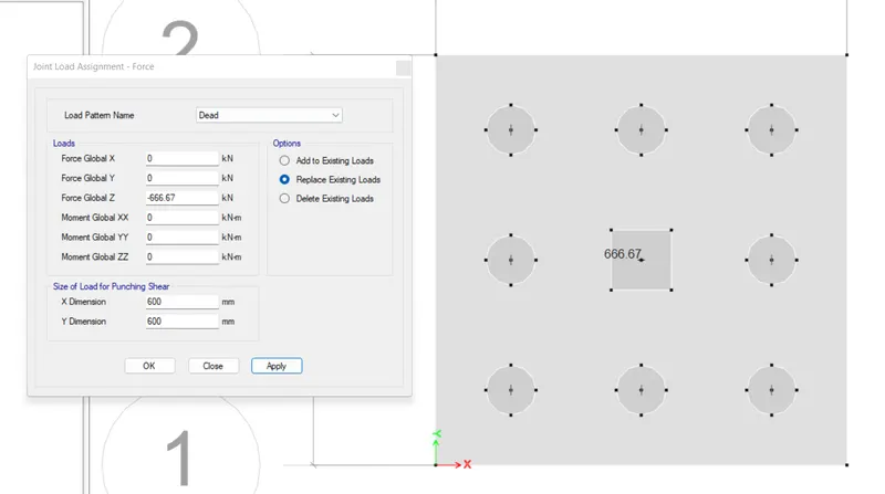
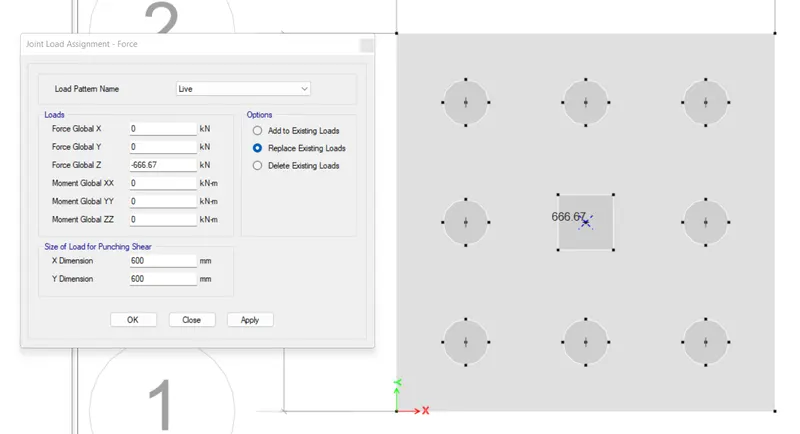
- Load Assignments
Dead Load
Live Load
- Define Load Combinations
Service Load Combo
Ultimate Load Combo
- Run the Analysis and Design
- Now that all things are set, we can run the analysis and design by clicking on the play button from the top tool ribbon in SAFE.
- The analysis will get completed within a few seconds and we will need to execute several checks as we did in the case of the isolated footings.
- So, the procedure shall be exactly the same and you can refer to the isolated footing section for a more detailed procedure.
- Here, we have included the final results of the design check as follows:
- Check for Settlement
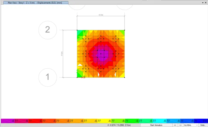
- Maximum displacement (6.77mm) is way lesser than the permissible value stated by the codes (25mm). Hence, OK.
- Punching Shear Check
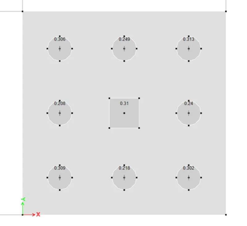
- Allowable punching shear value is equal to unity. Hence, OK.
- Base Reactions at Piles
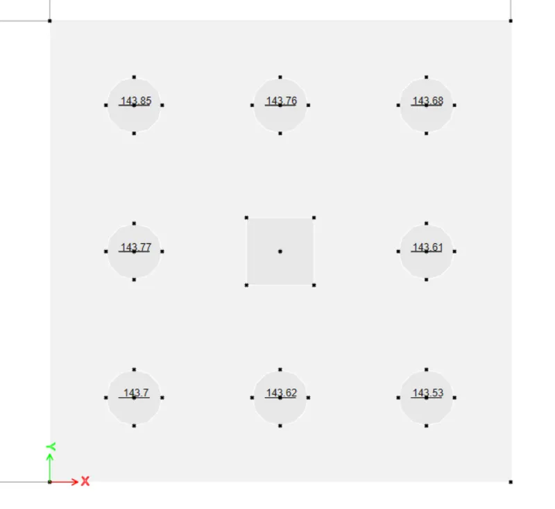
- Our pile bearing capacity is 200KN. Hence, OK.
- Longitudinal Reinforcement Requirement
Maximum Rebar Area for Design Strip A
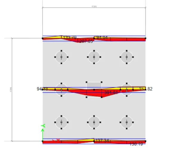
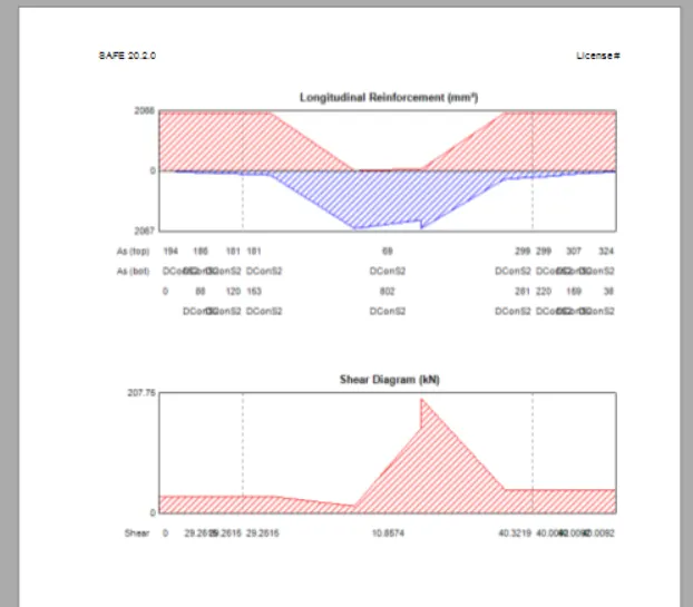
Maximum Rebar Area for Design Strip B