Foundation Design using SAFE
1. Model the isolated footing provided in week 11 challenge on SAFE. Analyze and design it to verify the size, depth and steel provided as per calculations.
Aim : To model the isolated footing provided in Week 11 challenge on SAFE.
Introduction: In this task we will open the Etabs model and link that model to SAFE so that the isolated footing is created on that model based on the loads and characteristics properties defined.
Procedure:
- Open week 11 challenge model on ETABS.
- Do the necessary checks and check whether all the loads are defined and rerun the analysis.
- Now go to File tab> Export > and click on Story as SAFE V12 . f2k file as shown in fig 1A.
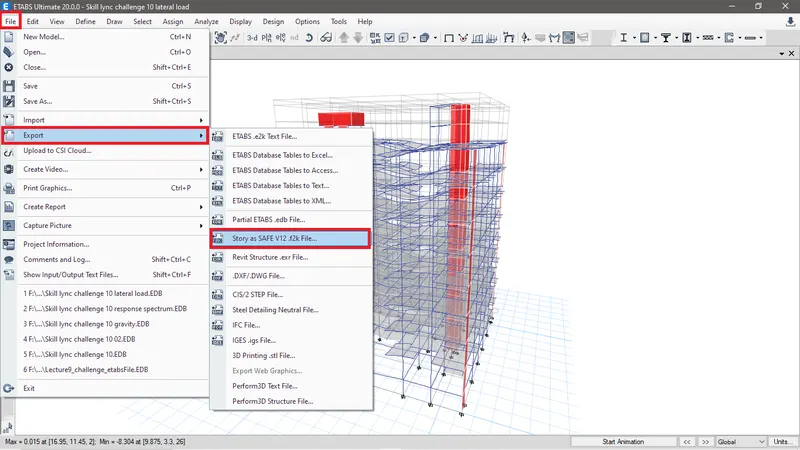
Fig 1A) Step to Export
- Now select Story as Base and check floor loads and load from above and select all the load cases and load combination and click on OK as shown in fig 1B.
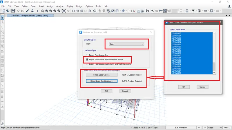
Fig 1B) Define properties to export to SAFE.
- Now save the file with the respective title as shown in fig 1C.
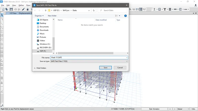
Fig 1C) Save the file.
- Now open SAFE software and go to File > Import > SAFE F2k file, As shown in fig 1D
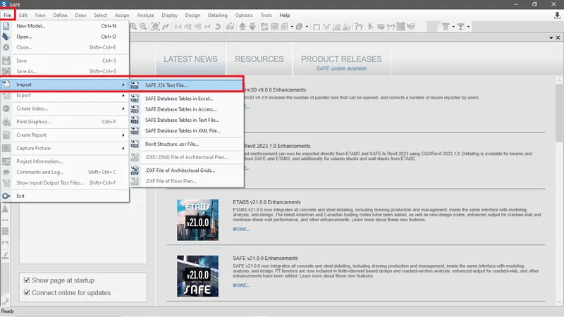
Fig 1D) To import SAFE f2k file.
- Now select the saved f2k file and click on Open, as shown in fig 1E.
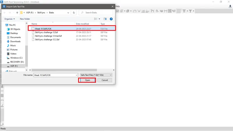
Fig 1E) Open f2k file.
- The file is now opened in SAFE with all the grids points and load cases and combination as defined in the model saved from ETABS. The fig 1f shows the SAFE model imported from ETabs.
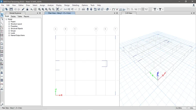
Fig 1F) Opened F2k file.
- Now define the material as usually that is Concrete having M25 grade and Steel of Fe500. Create a slab section of Isolated footing of desired dimension having minimum depth of the footing 450 mm.
- Now assign the sections to the location as required as shown in fig 1G.
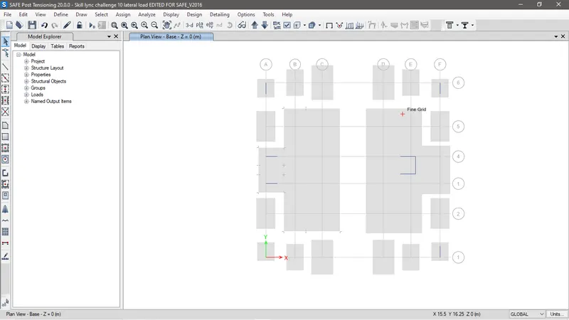
Fig 1G) Footings assigned to the desired loaction as required
- Stiff walls and columns also assigned on it desired loaction of desired size, as shown in fig 1I.
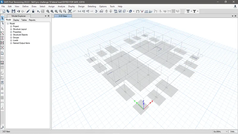
Fig 1I) Column and walls assisgned.
- Now need to assign soil support to the footing and that is done by first defining the soil support data and it is done by going to Define tab > Spring properties > Area Spring properties, as shown in Fig 1J.
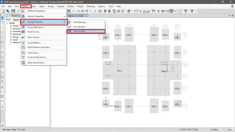
Fig 1J) Area spring for soil properties defining.
- Define the properties as per the test report as shown in fig 1K.
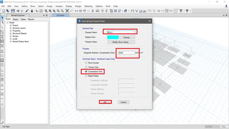
Fig 1K) Area spring for soil properties defining.
- Now go to select tabe > Section > Properties and select all the footings and then go to Assign tab > Shell > Area spring > Select defined area spring and click on Apply. We can see in Fig 1L that the Area spring is applied to the footing.
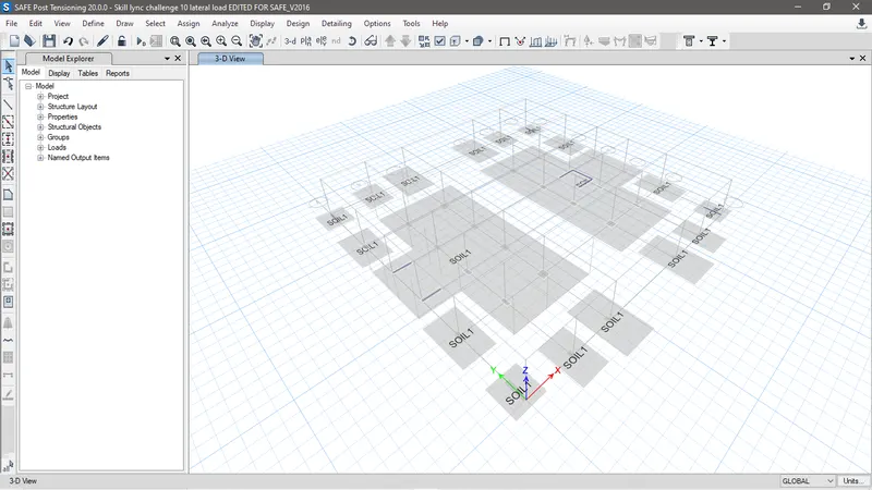
Fig 1L) Soil properties applied to the footing.
- Now run the analysis and check the displacement, soil pressure and Punting shear of the footing designed.
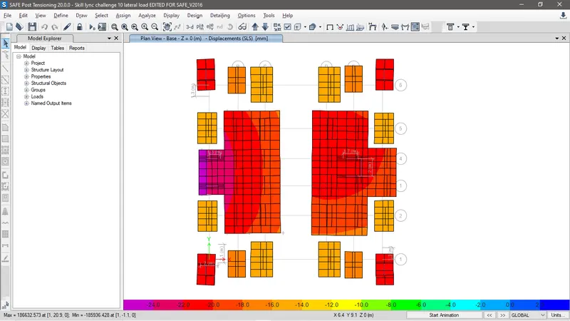
Fig 1M) Displacement check.
Fig 1M shows the displacement of the footing and it is found to be satisfying as the maximum displacement of the footing is 24mm which is less than 25mm.
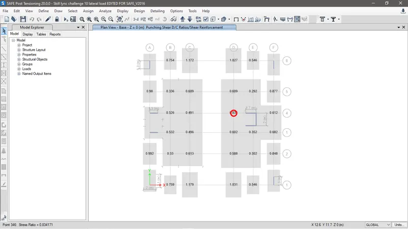
Fig 1N) Puncting shear check.
from fig 1N we can see that most of the puncting shear value is less than 1 hence the footing designed for that point of location is satisfying but the footing having more than 1 puncting shear value must be redisgned by increasing its depth and size of the footing so to achieve satisfied value.
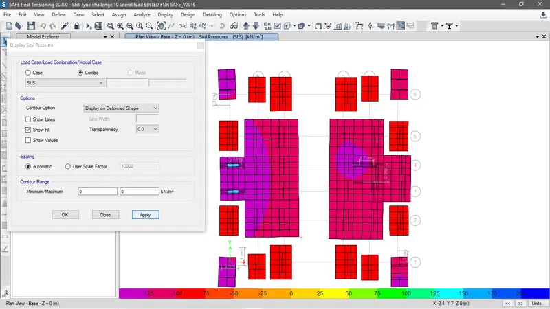
Fig 1O) Soil pressure check
Fig 1O shows that the soil maximum soil pressure is 125Kn/m2 which is less than 150Kn/m2 soil bearing capacity hence the result is satisfying.
- Now let's find out the steel rquired for each foudation.
First add strips as we usually add both in X and Y directions as shown in fig 1P.
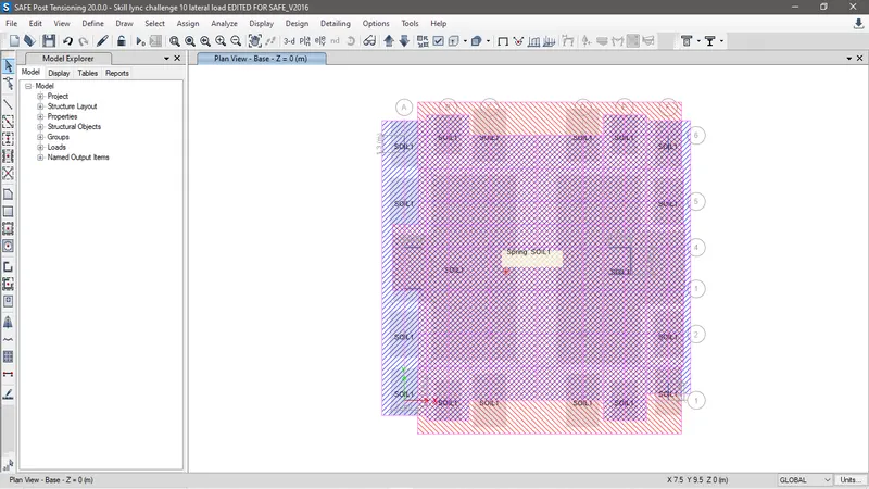
Fig 1P) Strips added
Now run the analysis and go to show slab design in display tab, we will find the result of the steels required as shown in fig 1Q.
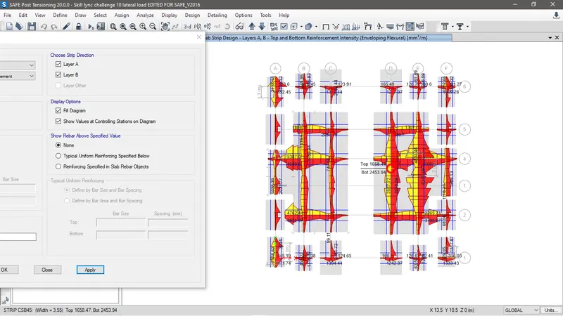
Fig 1P) Steel design based on strips.
Conclusion
The model in the SAFE is imported from the ETabs and the footings are designed as per the IS codal provisions. The model undergone Soil bearing, Displacement and Puncture shear check and found out to be that the the Puncture shear is not being satisfied to some of the footings and hence required changes in the design of those particular to achieve the required result. The Model undergone reinforcement design and achieve required result to understand the reinforcement requirement.
2. A column of size 600x600 carrying an unfactored gravity load (DL+LL) of 1175 KN is to be supported on pile cap, which ultimately transfers load to the piles underneath. Piles of 16 metres length and 500 mm diameter are to be used. Each pile has a load carrying capacity of 200 KN. Model, analyse and design the pile cap on SAFE to evaluate the following:
- Pile group to be used
- Depth of pile cap
- Longitudinal steel on top and bottom face in both directions
Aim: To model and desing pile and pile cap using safe with the from the given details.
Introduction: In this task with the help of Safe software we will design pile and pile cap with necessary checks as per IS 2911 (Part 2) SP 34. With the help of the software we will be abled to easily understand the efficiency of the pile designed and do the necessary changes for better output.
Procedure:
- First let's find out no of pile caps required under each pile cap carrying unfactored load of 1175Kn.
We know that the pile capacity of each pile is 200Kn.
Hence,
No of piles = Total axial unfactored load*assumption of soil load / Pile capacity = 1175*1.1/200= 6.46.
:- Consider 8 Nos of Piles under each pile cap to maintain symmetric.
- Let's calcualte the size of the pile cap.
We know that the dia of the pile is 500 mm. As per IS code the spacing between 2 pile should be greater than 2.5 times the dia of pile that is 1250mm and edge spacing should be minimum 200-300 mm. Considering edge spacing 200 mm.
Hence the length of the pile cap would be = 450+1250+1250+450=3400 mm.
The width of the pile cap would be = 450+1250+1250+450=2150 mm.
- Now, Open SAFE and click on New model.
- Define Country and their respective code book as shown in Fig A.
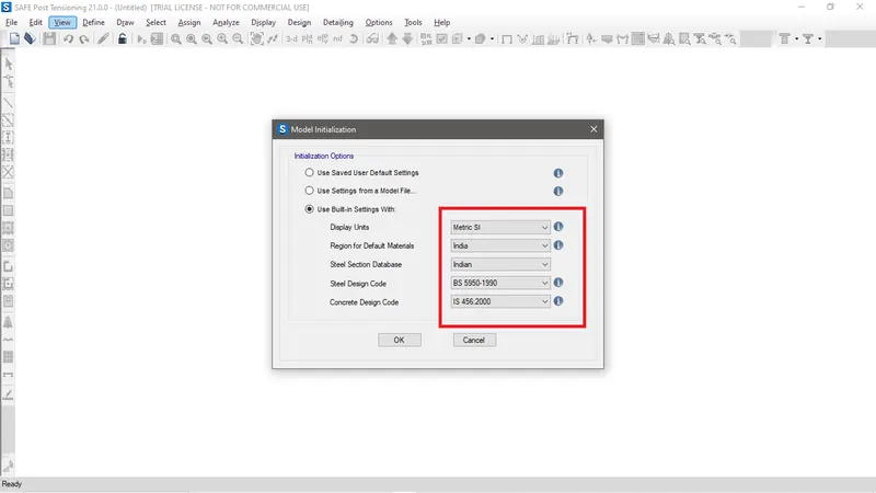
Fig A : Indian standard code book defined.
- Now select Grid only and check Uniform grid giving 2 numbers of grid in both the direction and length of the grid at X direction is 2.9 m and lenght of the grid at Y direction is 1.65m, As shown in fig B.
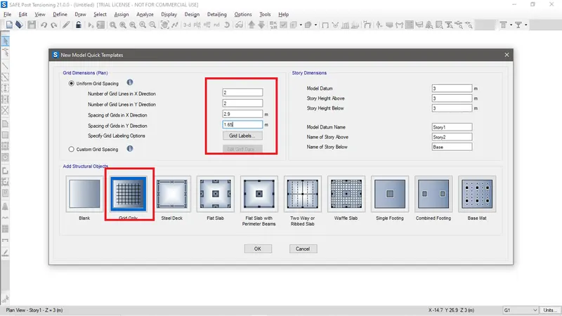
Fig B : Grids defined.
- Now define the material for concrete M25 grade and Rebar Fe500 as shown in fig C.
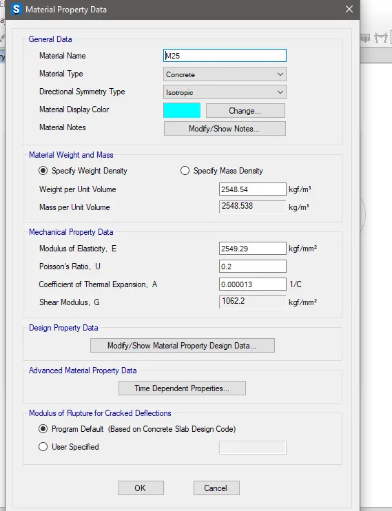
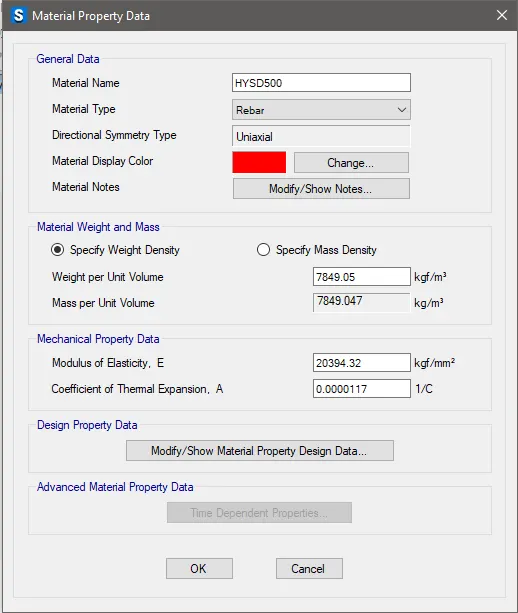
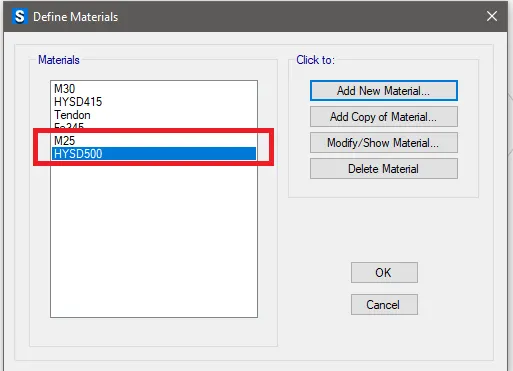
Fig C : Material property for M25 grade concrete and Fe500 Rebar defined
- Now define section properties.
Go to Define tab> Section properties > Slab sections. As shown in fig D.
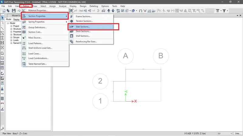
Fig D : Define slab sections.
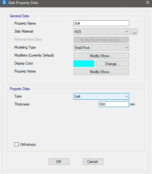
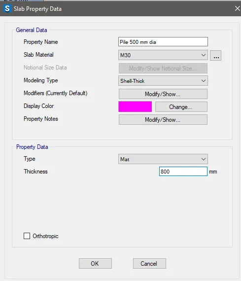
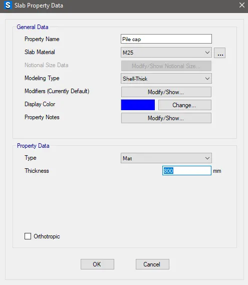
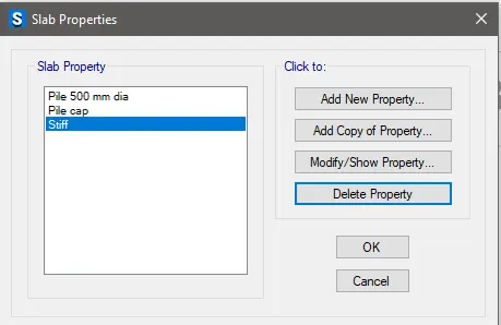
Fig E : Section for Pile cap, Column and Pile of 500 mm dia is define.
- Now lets draw the sections
First let's draw pile cap along the size of the grid. Click on Draw slab icon and select the require property for pile cap and draw on the grid points as shown in fig F.
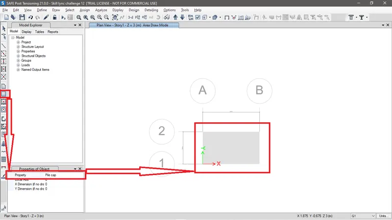
Fig F : Drawing of Pile cap.
Now lets draw the Piles. To do that first we need to set out the points on the pile cap at a required distance. To draw a point on pile cap go to draw tab> click on draw reference points as shown in fig G.
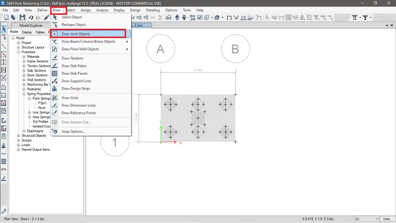
Fig G : Draw joint objects.
Define the X and Y location of the reference point and click on the particular point to achieve required ref point at required loaction, as shown in fig H.
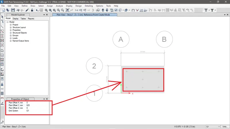
Fig H : Reference points drawn.
To draw circular pile cap click on click draw area around point> Define the object shape and provide it's dimension> click on the reference point. The circular pile cap will be drawn. Similarly draw the column as shown in fig I.
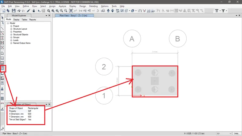
Fig I: Pile 500mm dia and column of 60X600 mm drawin.
- Let's assign spring constant on pile. First we need to calculate spring constant on each pile the formula for that is as follows.
Spring constant = EA/L
Herer E= 5000*sqrt(25)= 25000 N/mm2, A= (Pi*500*500/4)= 196349.54 and L=16000 mm
Spring constant = (25000*196349.54)/16000= 306796.15 N/mm
Since we found the value of spring constant. Now go to define tab > Spring properties > Point springs, as shown in fig J.
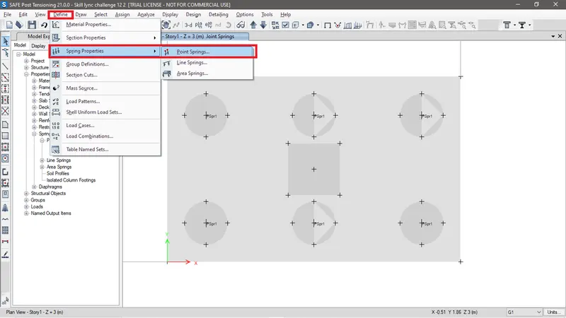
Fig J: Point springs.
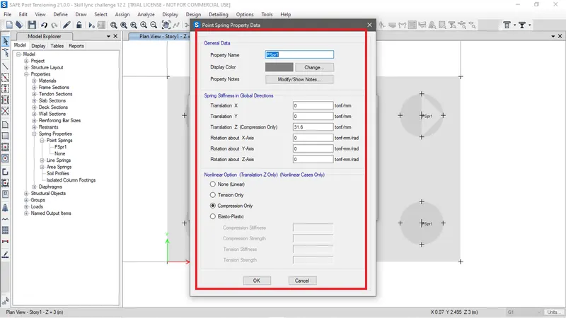
Fig K: Define point springs.
Now select the pile points and go to assign tab > joint> Spring as shown in fig L.
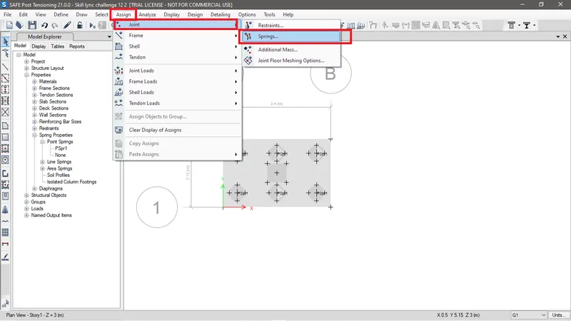
Fig L: Assign Spring.
Now select spring property and click on apply. We can see that point spring is assigned to selected joints, as shown in fig M.
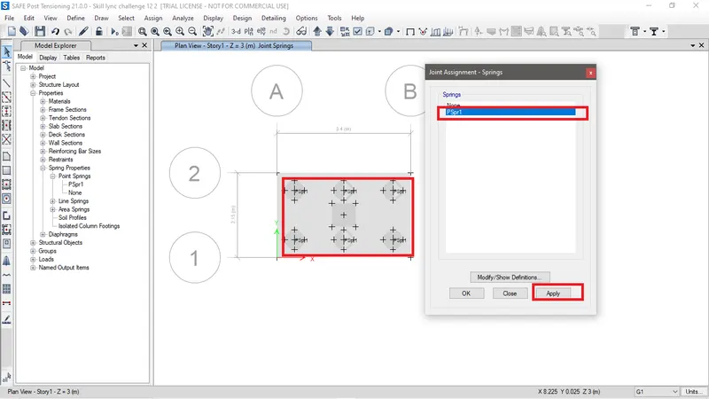
Fig M: Point spring assigned.
- Now add 1175 kn of point loads on the column.
Go to Assign>Joint loads > Force as shown in fig N.
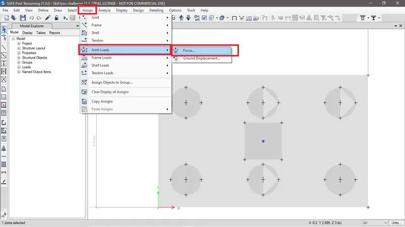
Fig N: Joint load.
Define the joint load as shown in fig o.
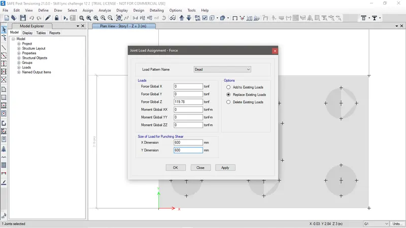
Fig O: Joint load defined.
- Now run the analysis and check for deflection, Reactions on pile and Puncting shear.
Click on Run analysis. Now we can see that the maximum deflection is -0.733 mm hence it is OK, as shown in fig P.
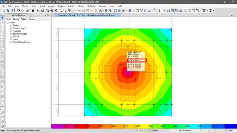
Fig P: Displacement check
Now to check reactions click on Reactions icon > Select load case as dead and point load and check Fz as display results and then click on apply. We can see that the reaction on pile is less than 20Tonnef. Hence it is Safe, as shown in fig Q.
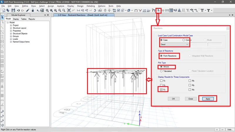
Fig Q: Pile reaction check
Now to check Puncting shear go to Display> Shown Puncting shear design as shown in fig R.
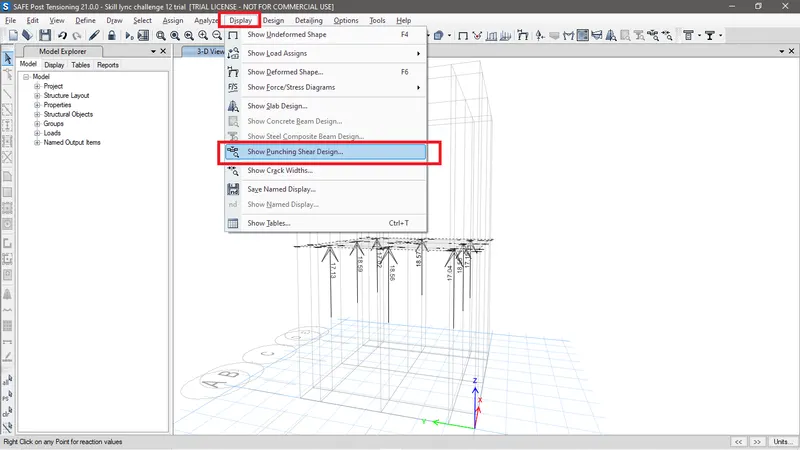
Fig R: Puncting shear design.
We can see Fig S that the punting shear value is less than 1. Hence the design is Ok.
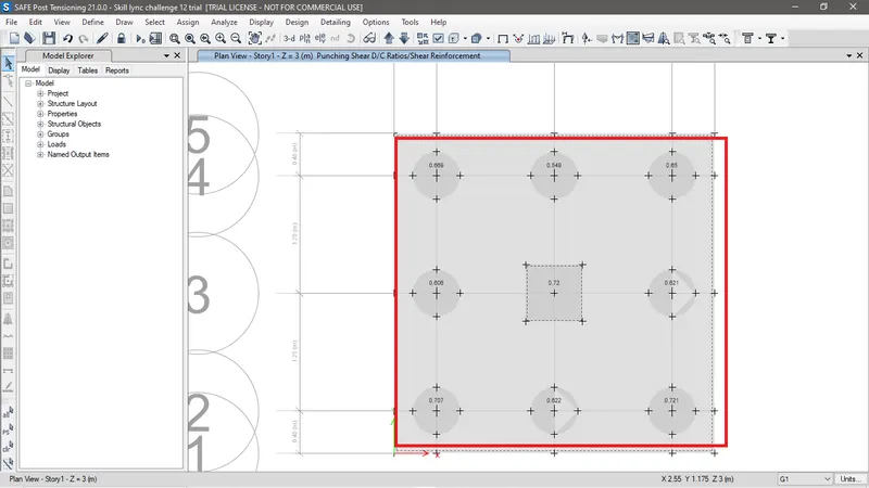
Fig s: Value of puncting shear design.
- Now we have found that all the checks of the pile cap is OK. Now let's proceed ahead to design reinforcement.
To design reinforcement for the pile cap we need to add strip in both the direction on the pile cap. In order to do that we need to go to Edit > Edit/add strip> add strip as shown in fig T.
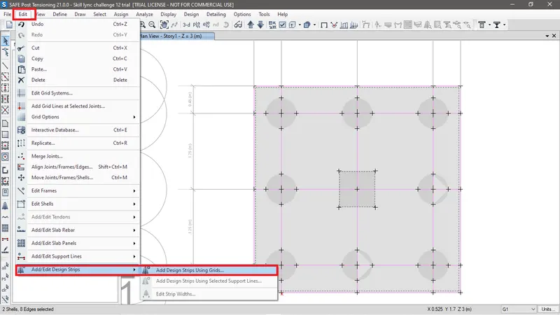
Fig T: Adding strip.
Now select X direction to add strip on X direction and layer for that A and similarly for Y direction use layer B as shown in fig U.
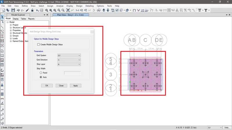
Fig U: Strip design added.
Now add Ultimate limit state combo having dead and live load safe factor as 1.5. In order to do that go to Define > Load combination > And new combo> and define the combos as shown in fig V.
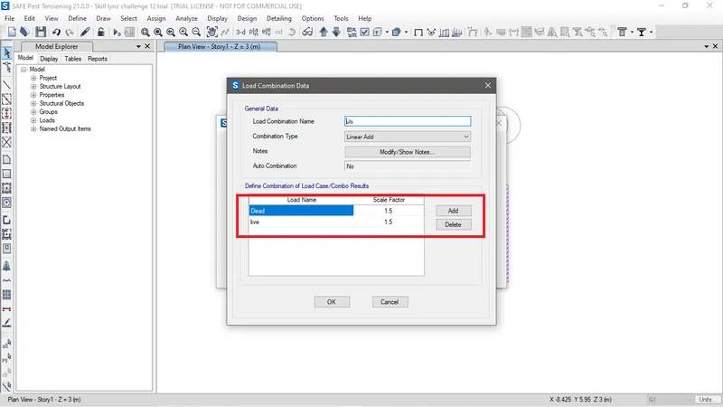
Fig V: Combos defined.
- Now run the analysis and go to Display> Display Slab Design > Select strip design (Check X direction) > Click on apply we will achieve Area of steel required design in X direction og the pile cap as shown in fig W. Similarly do the same for Y direction reinforcement details.
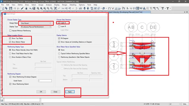
Fig W: Pile cap reinforcement design.
- As per the reinforcement reaquirement in both the direction at top and bottom layer the structural drawing of the pile caps are sketched down as shown in fig X.
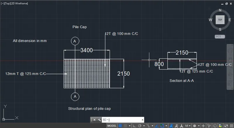
Fig X: Structural drawing of pile cap both in plan and sections.
Conclusion:
The pile cap is modeled and designed and analysed by SAFE and the result has found to be satisfying as per the codal provision.
The displacement is less than 5mm hence satisfied, the puncting ratio is less than 1 hence satisfied and the base reactions is less than pile bearing capacity, hence satisfied.
With the based on the reinforcement design on Etabs required number of reinforcement are drawn and defined.