Foundation Design using SAFE
Aim:
To Model and Analyze an Isolated Footing and Pile Foundation for the given Loading details using SAFE software and check for Permissible Limits as per Code.
Theory:
- The Isolated Footing is used in cases where there is enough Soil Bearing Capacity to support the Foundation.
- The Pile foundation is used in cases where there is not enough Soil Bearing Capacity to support the Isolated Footing so we go with Pile Foundation.
- The specifications of the Isolated Footing and the Pile foundation Detailing is given in IS 2911 Part-2 & SP 24.
Procedure:
1. Isolated Footing:
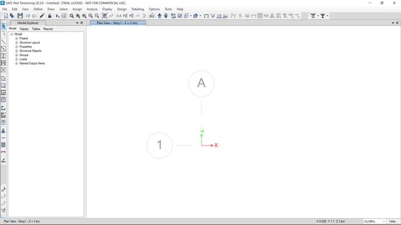
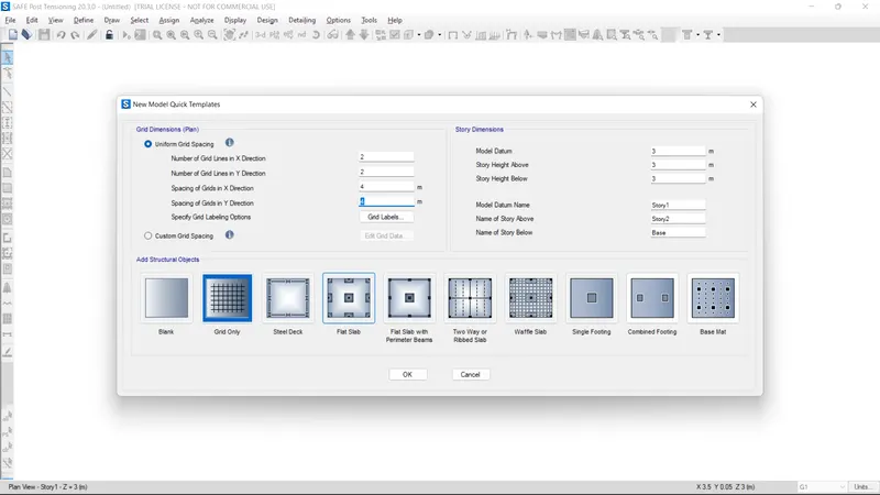
- Open the SAFE software and give the Grid details as per the given details.
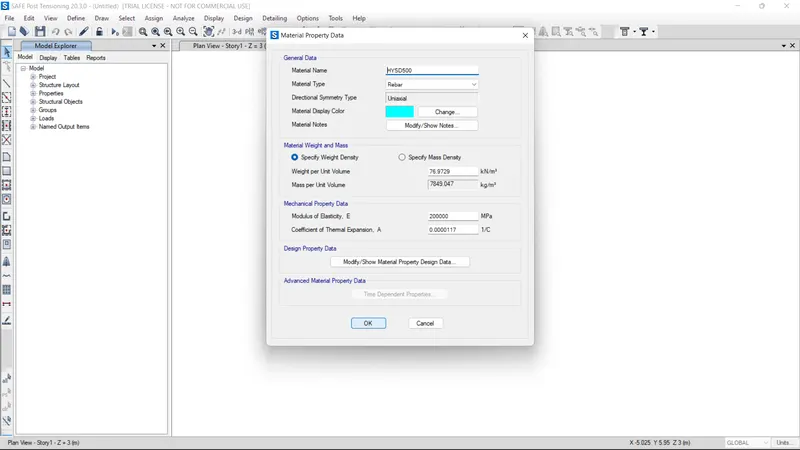
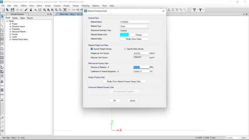
- Define the Material Properties of Concrete and Rebar Steel.
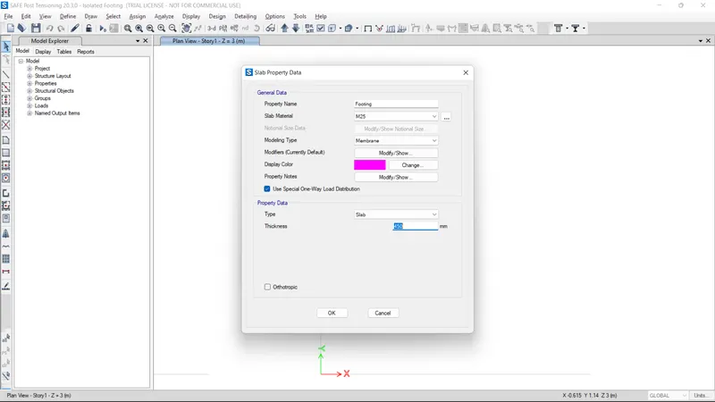
- Define the Slab Details for Column and Foundation.
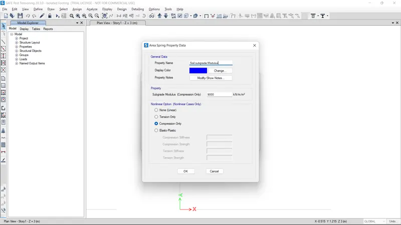
- Define the Soil Subgrade Property Data.
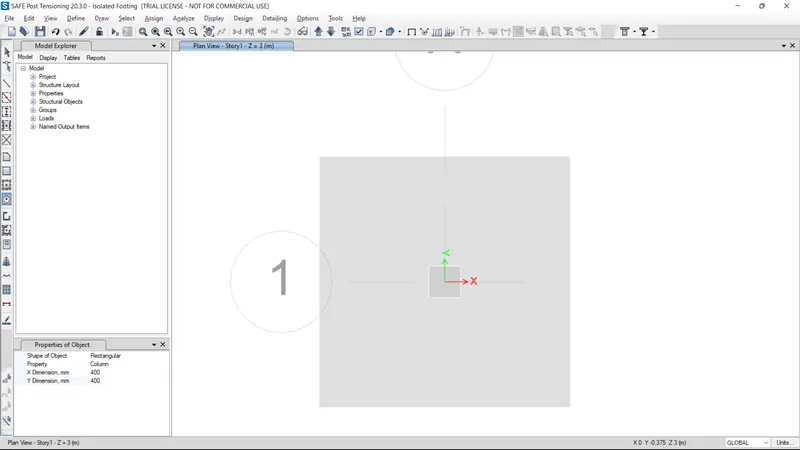
- Now model the Foundation and Column on the Grid created with respective dimensions for the Column and Foundation.
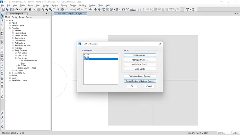
- Define the Load combinations for Ultimate and Servicability Limits.
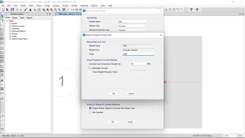
- Now Define Material Property Design Data.
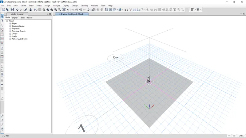
- Add the Loads to the Column joint for both Dead and Live Loads.
- Check in 3D view whether the loads are given or not.
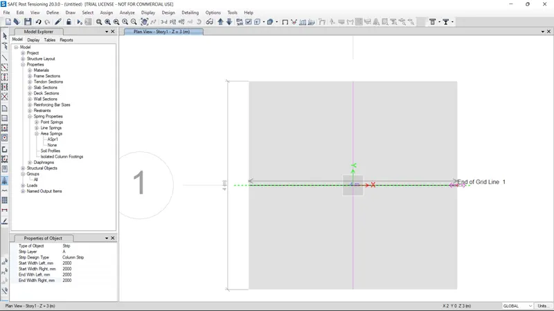
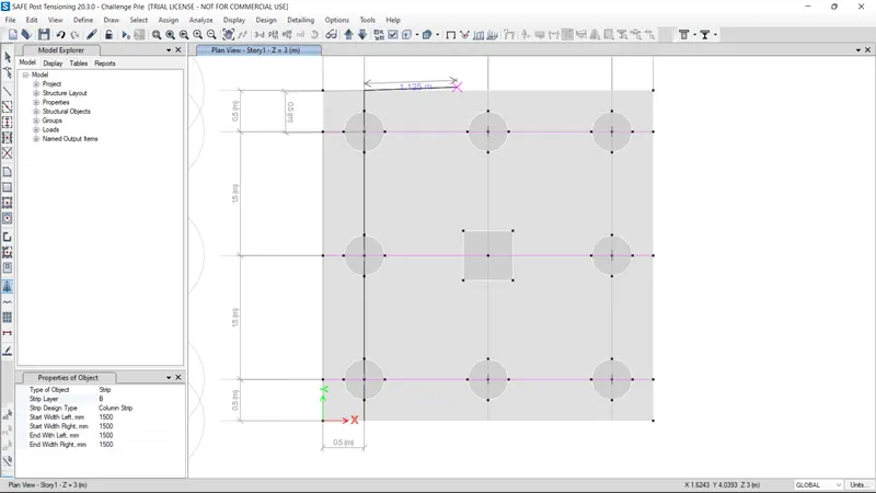
- Give the Design Strips in the Both directions Horizontally and Vertically with respective Design Strip Width.
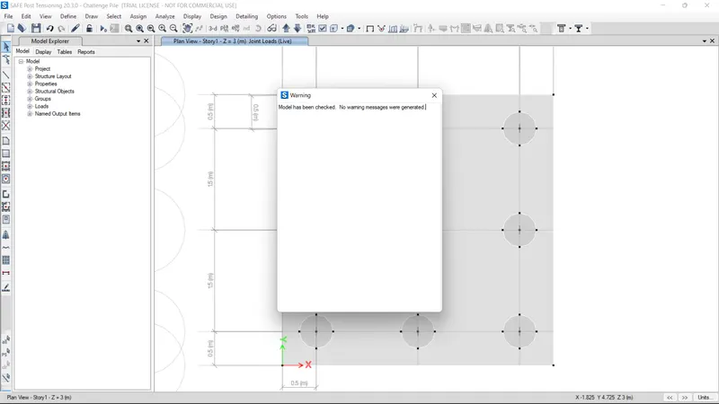
- Analyze the Model for the given Load combinations.
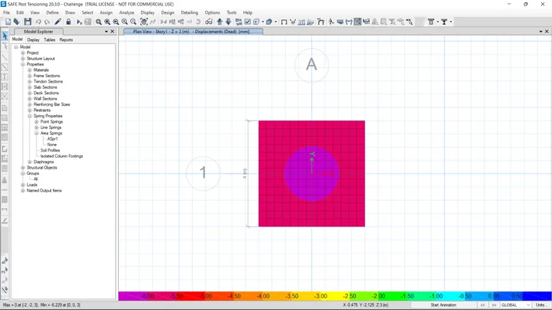
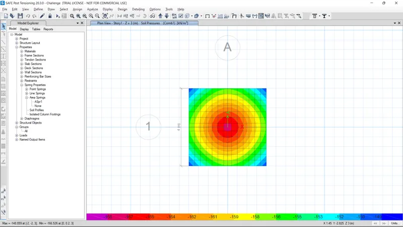
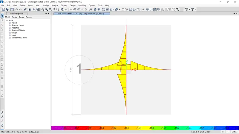
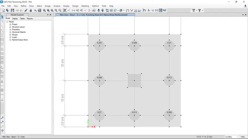
- Check the results for Punching Shear, Settlement and Bearing Pressure.
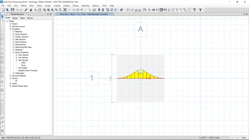
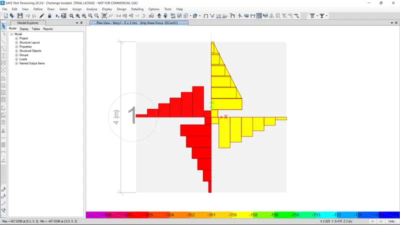
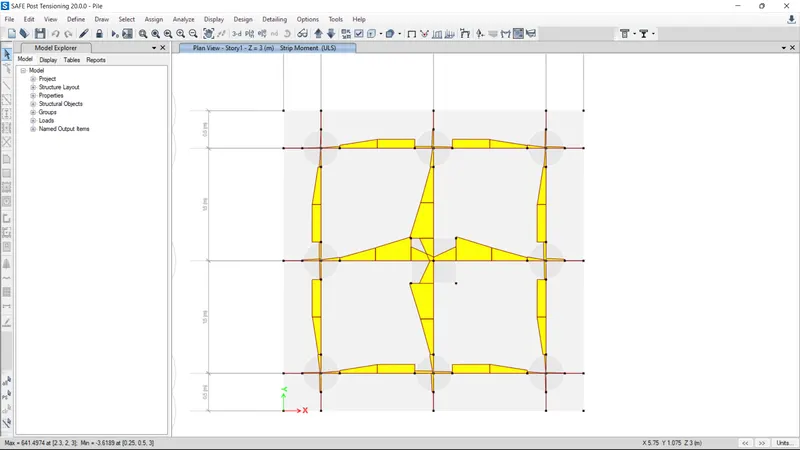
- Also go through the Shear Force and Bending Moment for the Design Strips.
2. Pile Foundation:
- Open the SAFE software and give the Grid details as per the given details.
- Define the Material Properties of Concrete and Rebar Steel.
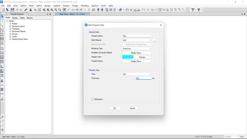
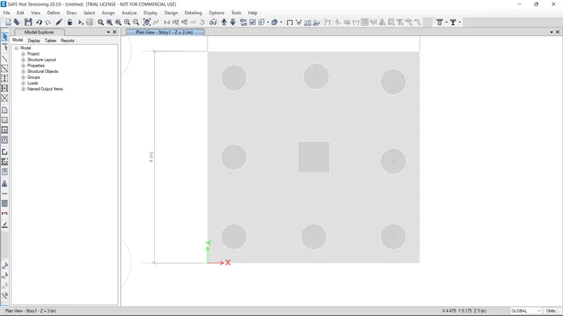
- Define the Slab Details for Column, Piles and Pile Cap.
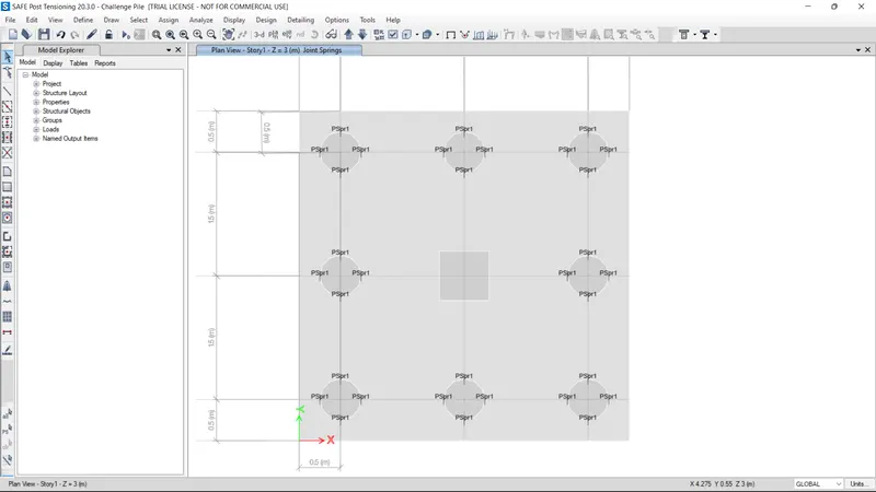
- Define the Spring Property as per the Formula based on the Length of the Pile.
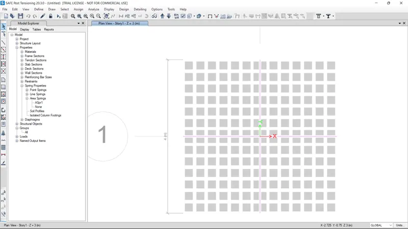
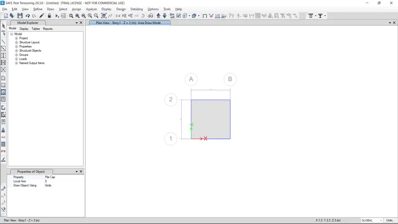
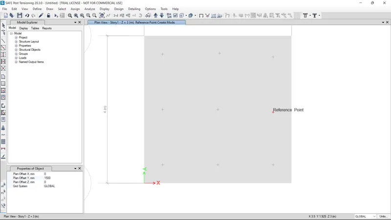
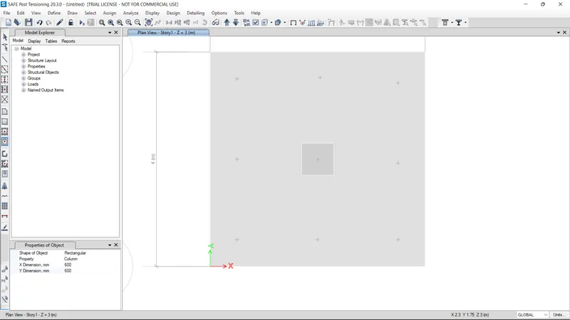
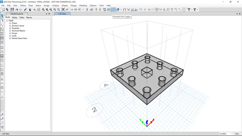
- Now model the Foundation and Column on the Grid created with respective dimensions for the Column, Piles and Pile Cap.
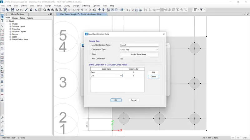
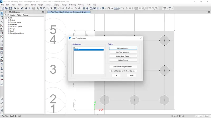
- Define the Load combinations for Ultimate and Servicability Limits.
- Now Define Material Property Design Data.
- Add the Loads to the Column joint for both Dead and Live Loads.
- Check in 3D view whether the loads are given or not.
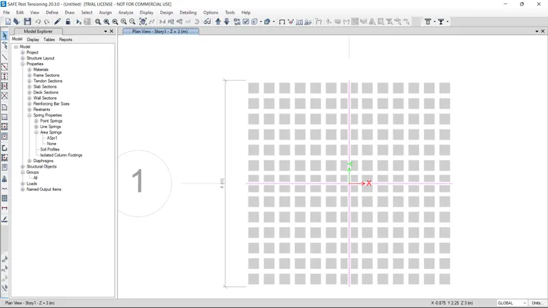
- Give the Design Strips in the Both directions Horizontally and Vertically with respective Design Strip Width.
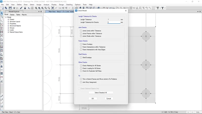
- Analyze the Model for the given Load combinations.
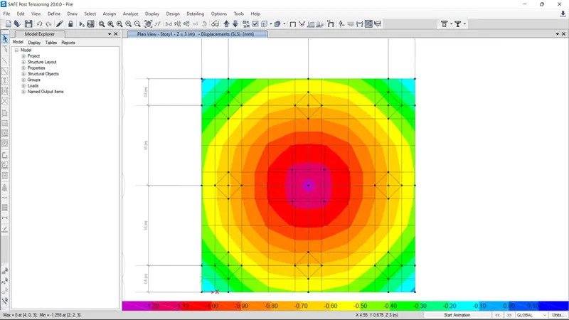
- Check the results for Punching Shear, Settlement and Bearing Pressure.
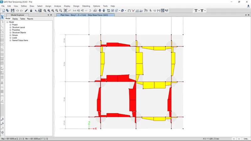
- Also go through the Shear Force and Bending Moment for the Design Strips.
Result:
The Isolated Footing and Pile Foundation have been Modelled and Analyzed using the SAFE software. The results are checked with respect to specifications.
The Files are attached for reference.