Foundation Design using SAFE
Question 1:-
Model the isolated footing provided in week 11 challenge on SAFE. Analyze and design it to verify the size, depth and steel provided as per calc9000ulations.
Data Given in Week 11 Challenge:
- Column size = 400x400
- Load combination of (1.5 DL + 1.5 LL) = 2000 KN
- The safe soil bearing capacity =150 KN/m2
- Assume M25 concrete grade.
Answer:-
Step 1:-
Unfactored Load = Factored Load / Factor of Safety
= 2000 / 1.5 = 1333.33 kN
Asuume Dead Load and Live load are equal.
Dead Load = Live Load = 1333.33 / 2 = 666.67 kN
Footing Area:
Footing Area = Unfactored load with surcharge + self weight of footing / allowable soil pressure
Add 10% of unfactored load for surcharge
= (2000/1.5x1.1) / 150
Footing Area = 9.78 m2
Let's assume the footing is Square.
=√9.78 = 3.13 m
Consider, 3.2 meter sided isolated square footing.
Subgrade Modulus of Soil = Safe Bearing Capacity x Ultimate factor / Maximum allowable settlement
= 150 x 3 / 0.05
k = 9000 kN/m3
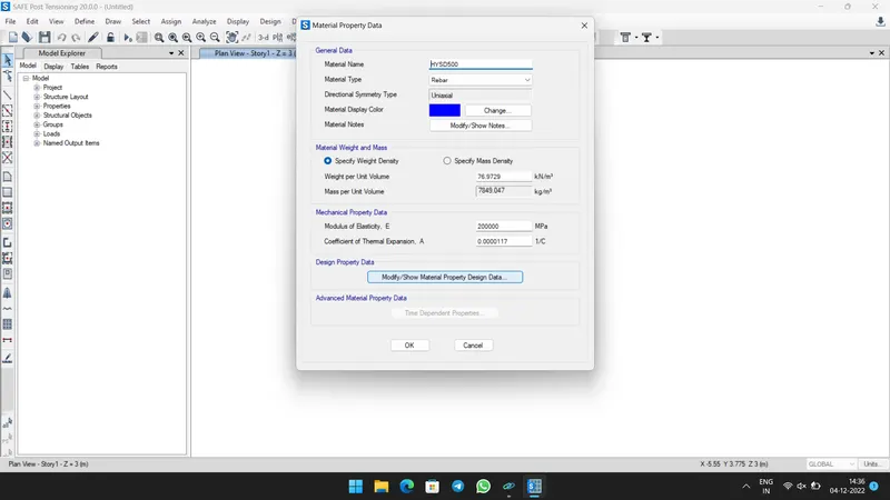
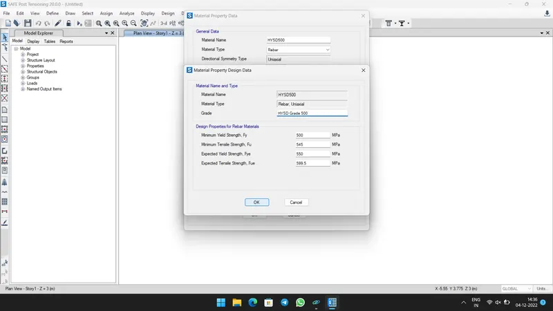
Assume Rebar as Fe500
Rebar yeild strength (fy) = 500 N/m2
Ultimate Strength (fu) = 545 N/m2
Elastic modulus of M25 concrete = 5000 x √fck
= 5000 x √25
Ec = 25000 N/mm2
Step 2:-
- Open SAFE Software.
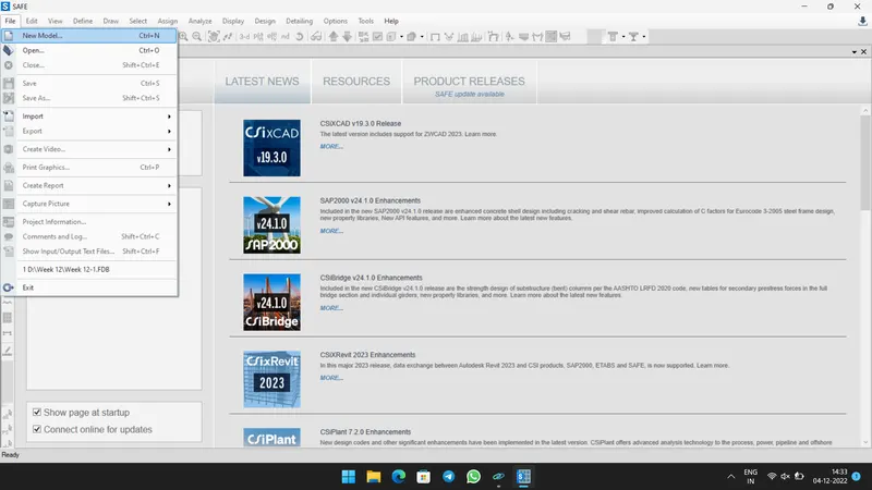
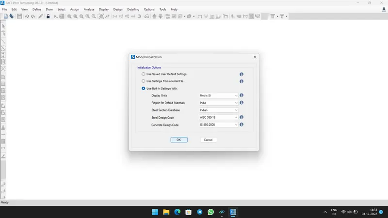
- In Initialization Window, Set up the Display units and code as shown below. Then Click OK.
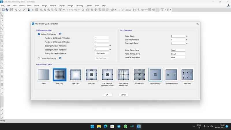
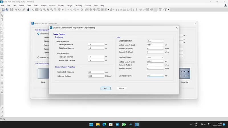
- Now Quick Template window open, select Isolated footing and give inputs as shown below.
Step 3 :-
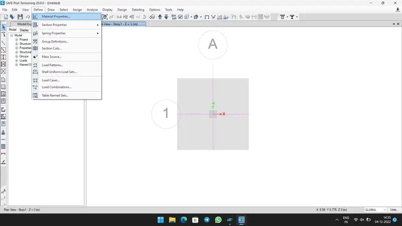
- Select Materials properties from Define tab.
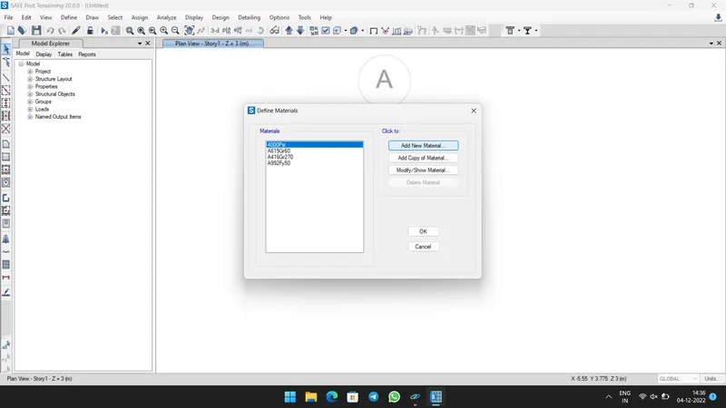
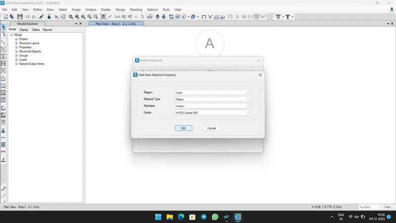
- Then click Add new property.
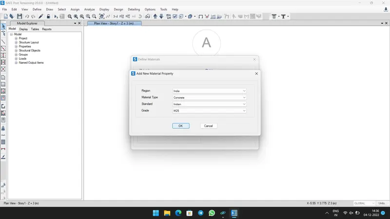
- Select concrete and name as M25.
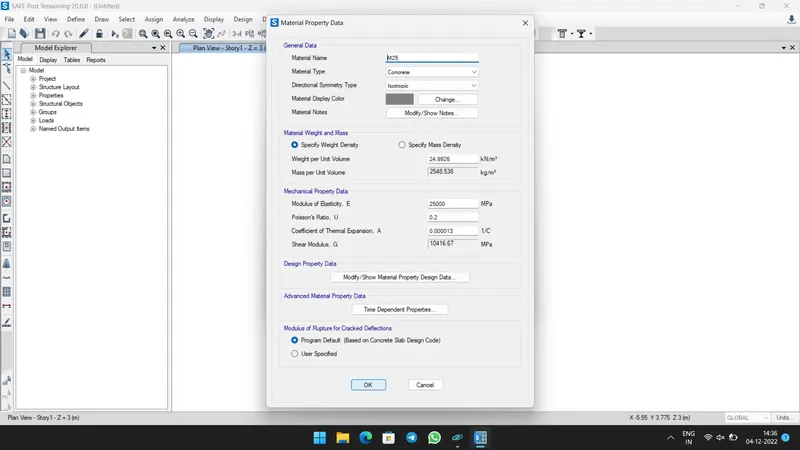
- Similarly define Fe500 rebar and check inputs.
Step 4:-
- Now check Soil subgrade properties, Area Springs under Spring properties .
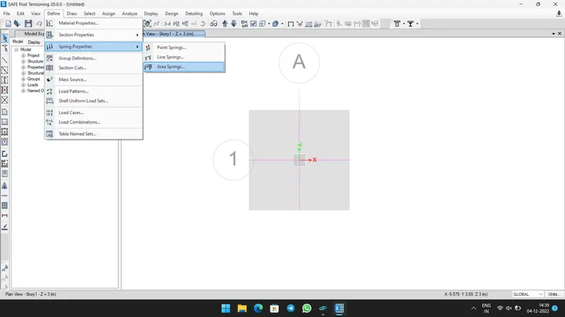

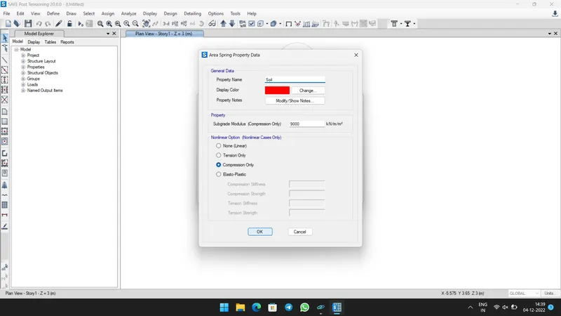
Step 5:-
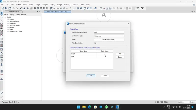
- Now Select Load combination data from Define tab.
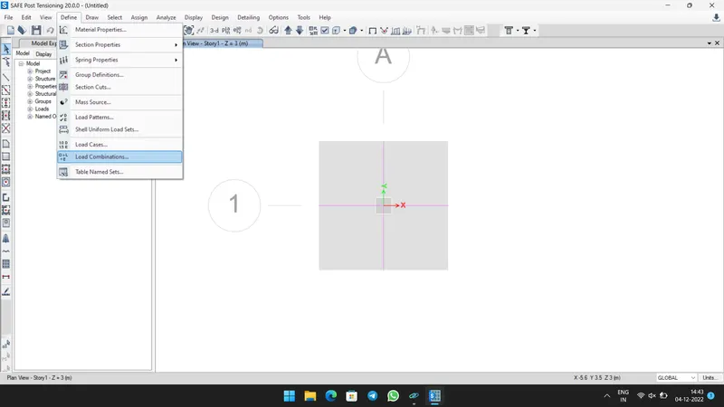
- Then Create Service LOad combination (DL+LL) and Ultimate Load combination (1.5DL+1.5LL).
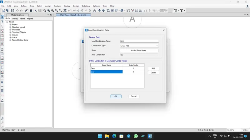
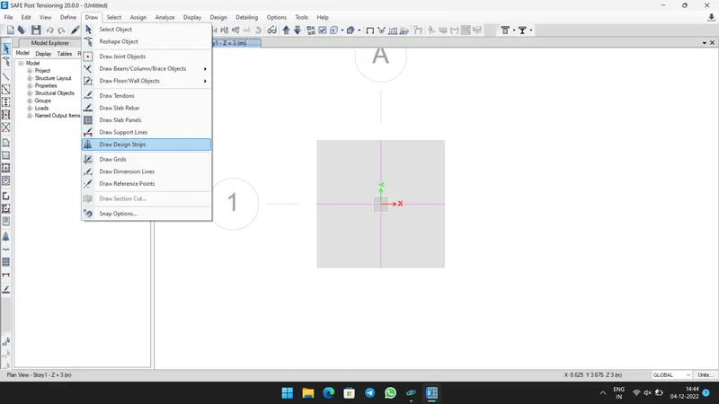
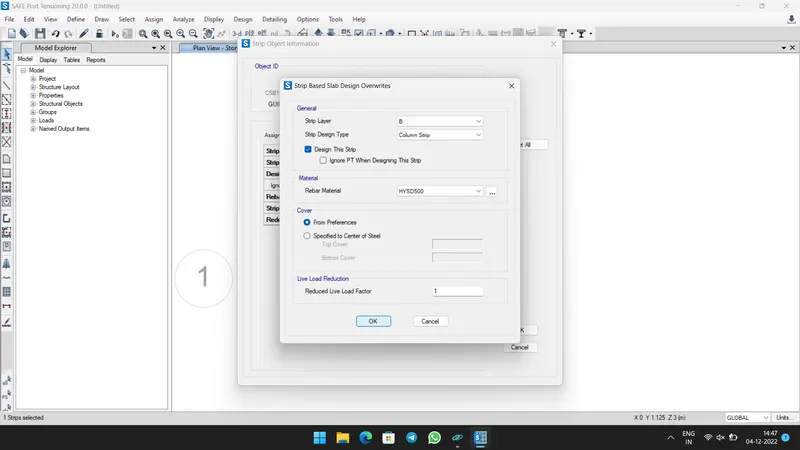
- Then Draw Strips along both direction of footing as shown below.
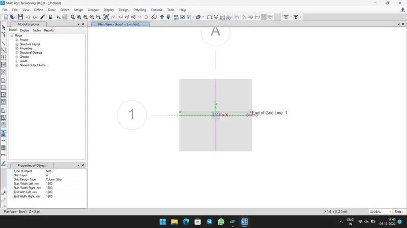
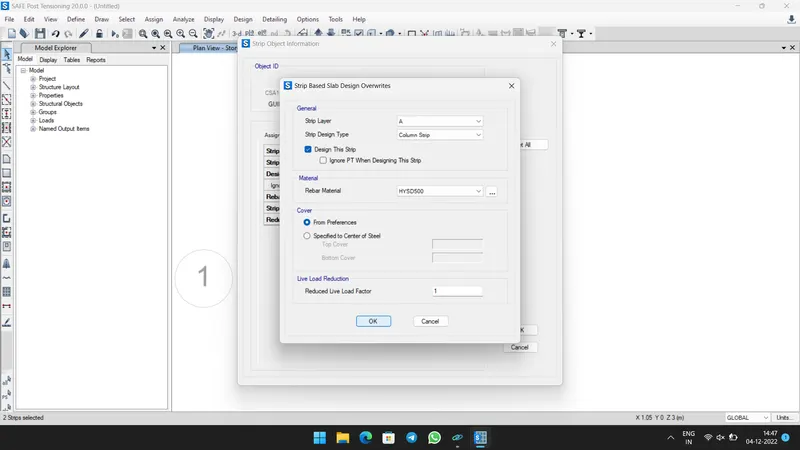
- Then check whether the Strips input are assigned well.
Step 6:-
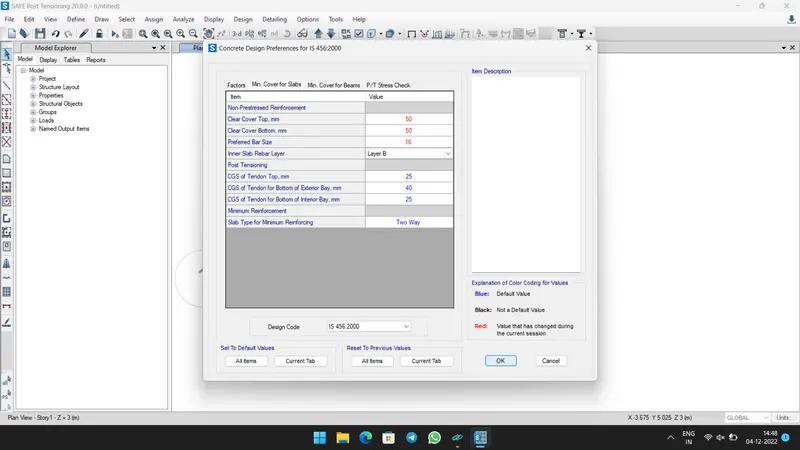
- Check Design Preferences and change minimum cover as 50mm.
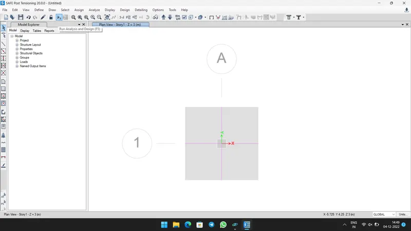
- Now click Run Analysis.
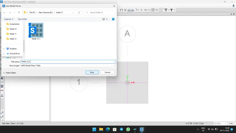
- To Run Analysis, first save the file at appropriate location.
Checks need to be performed in SAFE Analysis:
- Safe Bearing Capacity under Service load
- Settlement under Service load
- Two way shear check (Punching Shear)
- Ultimate Bending moment
- Flexural reinforcement design for Footing slab.
Step 7:-
- Click Display soil Pressure, then select SLS load Combination.
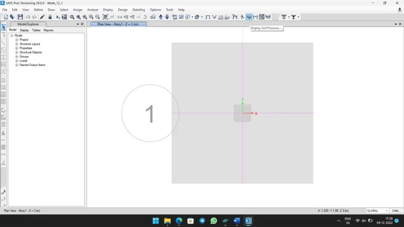
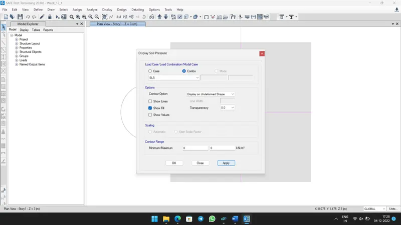
- And check Soil Pressure.
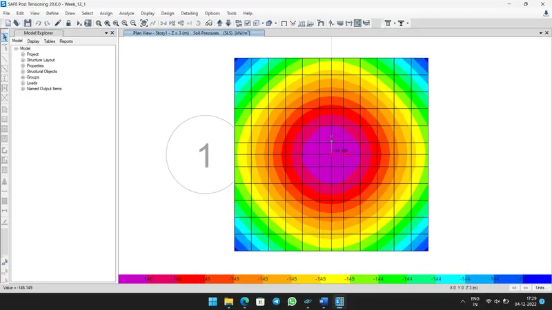
- Soil Pressure (146.149 kN/m2) is lesser than Safe bearing capacity (150 kN/m2).
- Hence Safe.
Step 8:-
- Click Show Deformed Shape, then select SLS load Combination.
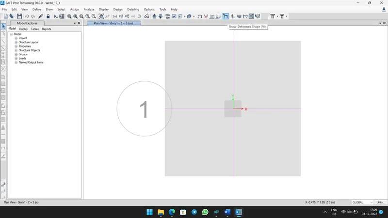
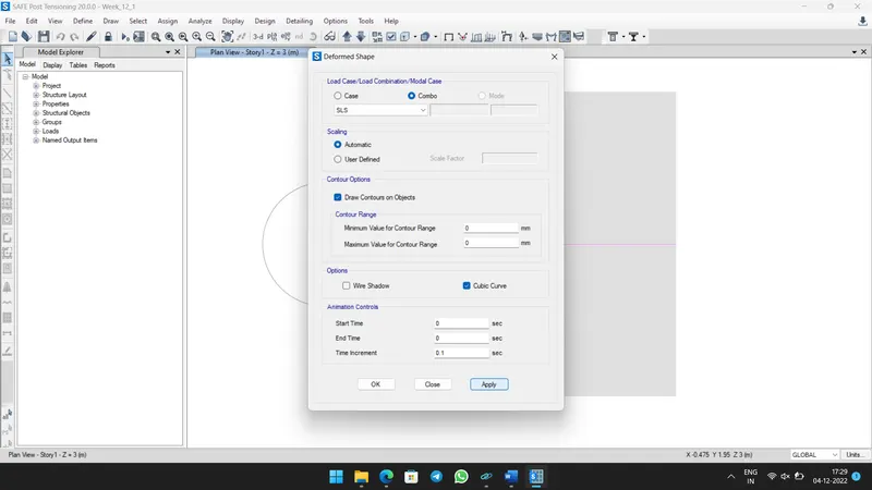
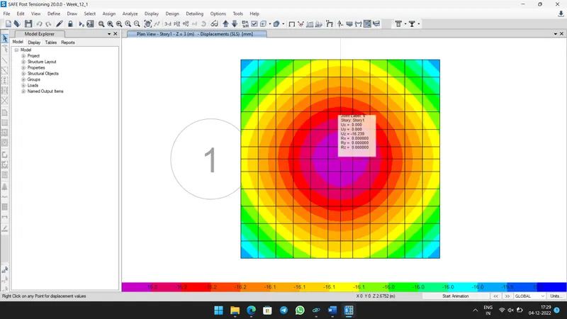
- It shows the maximum deflection of 16.239mm.
- Displacement (16.24 mm) is lesser than Maximum allowable settlement (50 mm).
- Hence Safe.
Step 9:-
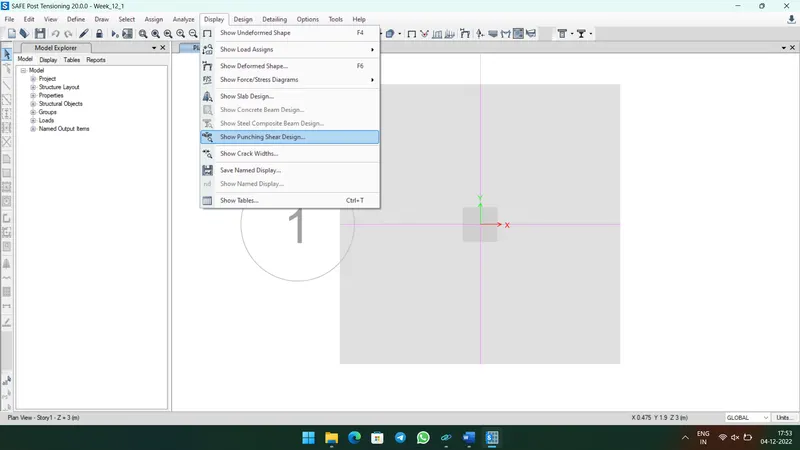
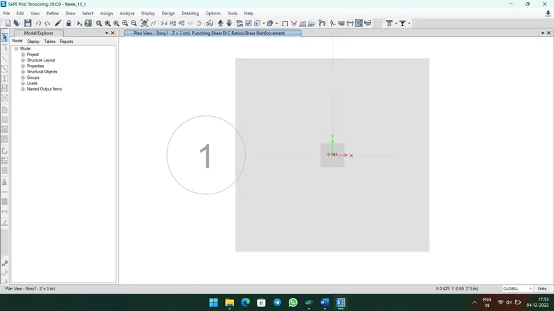
- In Display Tab, Select Show Punching Shear.
Step 10:-
- Then Select Slab Design under Display tab, using Strip Based and check Minimum Reinforcement.
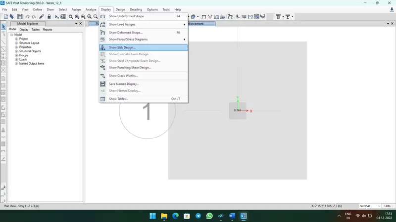
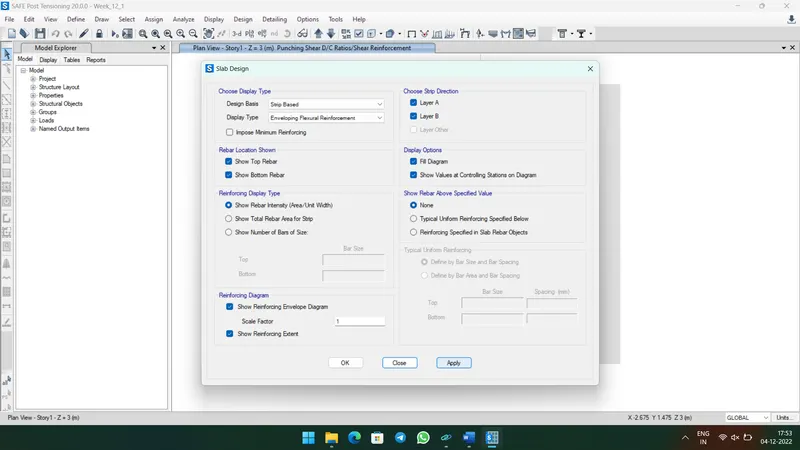
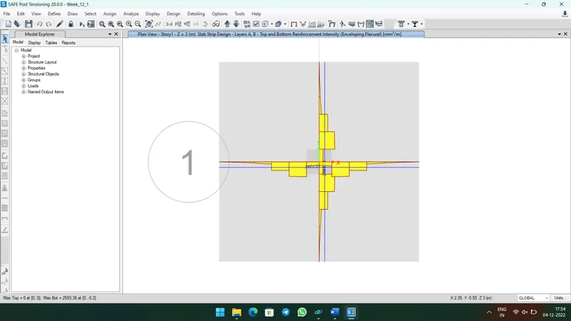
- Minimum reinforcement required along X-Direction is 2477.71mm2 and Minimum reinforcement required along Y-Direction is 2593.35mm2
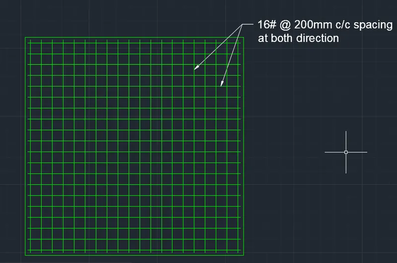
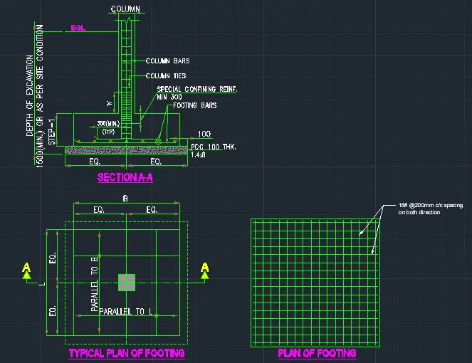
- Hence provide 16mm dia bar at 200mm c/c spacing on both direction at Bottom layer.
Result:-
Analyse and design of Isolated Footing was done by using SAFE Software.
Question 2:-
A column of size 600x600 carrying an unfactored gravity load (DL+LL) of 1175 KN is to be supported on pile cap, which ultimately transfers load to the piles underneath. Piles of 16 metres length and 500 mm diameter are to be used. Each pile has a load carrying capacity of 200 KN. Model, analyse and design the pile cap on SAFE to evaluate the following:
- Pile group to be used
- Depth of pile cap
- Longitudinal steel on top and bottom face in both directions
Given Data:
Column Size = 600 x 600
Unfactored Load (DL + LL) = 1175 kN
Pile Length = 16000 mm
Pile Diameter = 500 mm
Load Carrying capacity of each Pile = 200 kN
Answer:-
Step 1:-
Assume Dead load is equal Live load.
DL = LL = 1175 / 2 = 587.5 kN
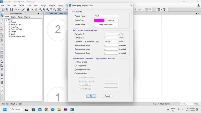
Point Spring of Pile = AE/L
= 196349.54 x 25000 / 16000
= 306796 N/mm
k = 306796 kN/m
Assume Rebar as Fe500
Rebar yeild strength (fy) = 500 N/m2
Ultimate Strength (fu) = 545 N/m2
Elastic modulus of M25 concrete = 5000 x √fck
= 5000 x √25
Ec = 25000 N/mm2
Number of Piles required = (Unfactored load + Self Weight) / Individual load carrying of Pile
Lets assume Self weight = 10% of Unfactored load.
= (1175 x 1.1) / 200
Number of Piles required = 6.5
Consider 8 Piles to be provided for arrangement.
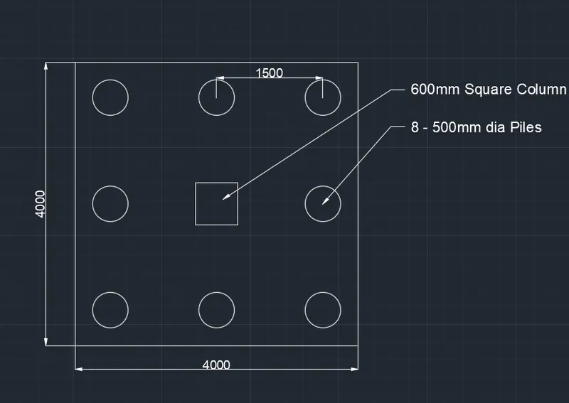
Take center to center distance between the Piles is 3 times of Pile diameter (1500mm) and Edge distance from pile is 1 time of Pile diameter (500mm).
Placement of Piles:
Step 2:-
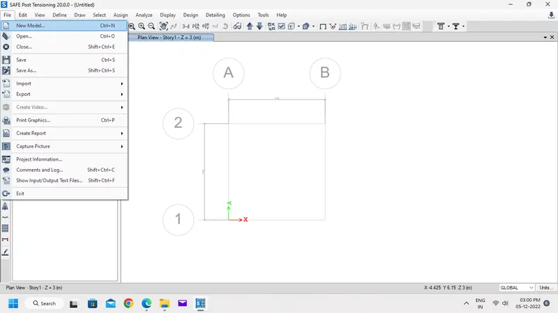
- Open SAFE Software, Select New Model from File Tab.
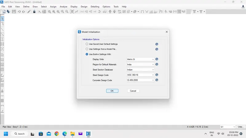
- Then set up Model initialization ass shown below.
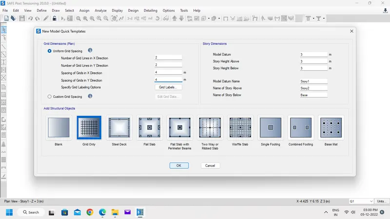
- Now select Grid type in Quick Template and give input as shown below.
Step 3:-
- Define materials properties from Define Tab.
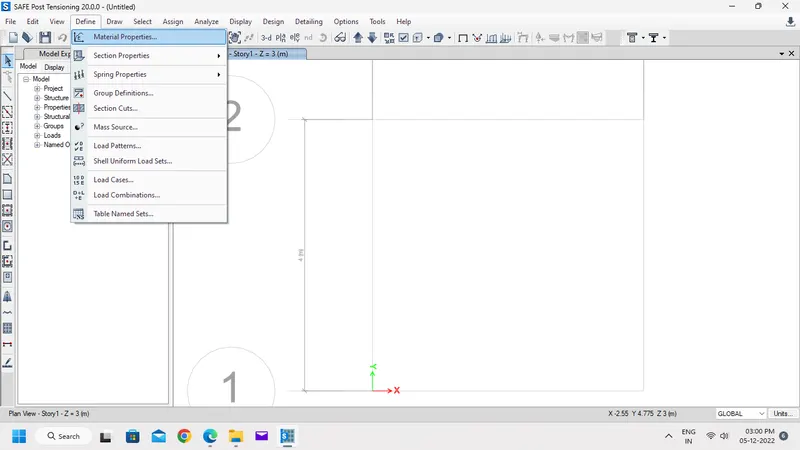
- Then select Add New Material and select M25 concrete as shown below.
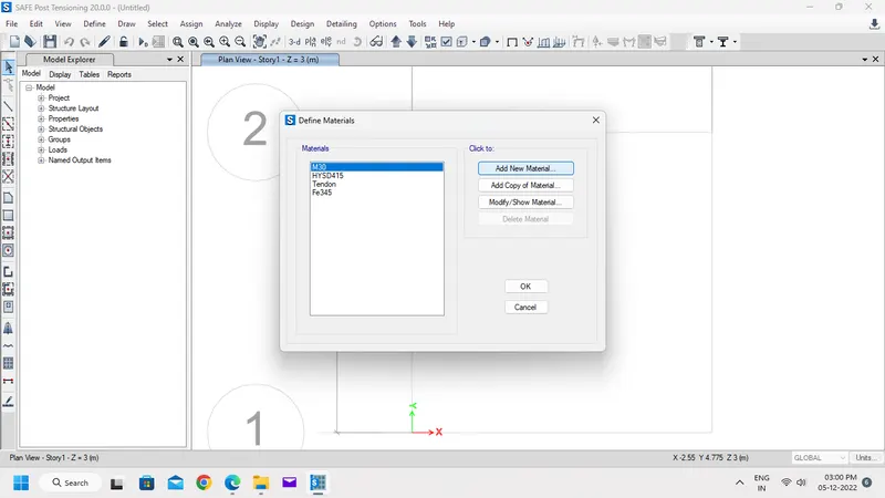
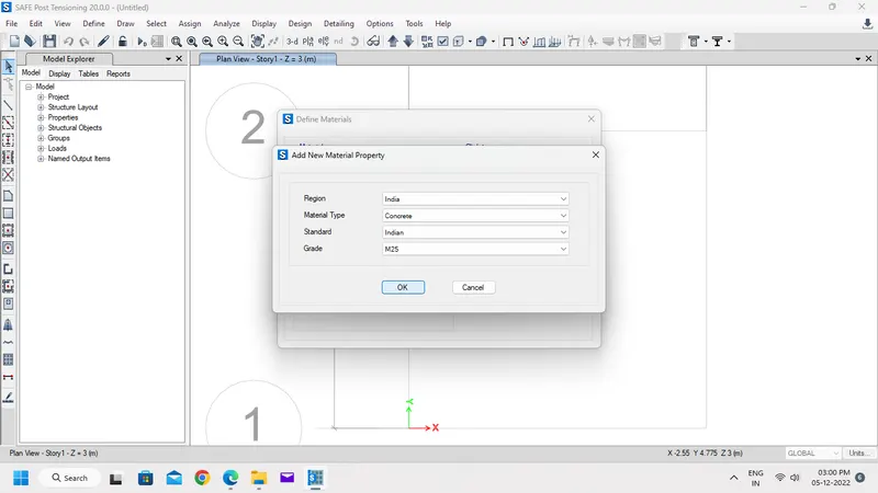
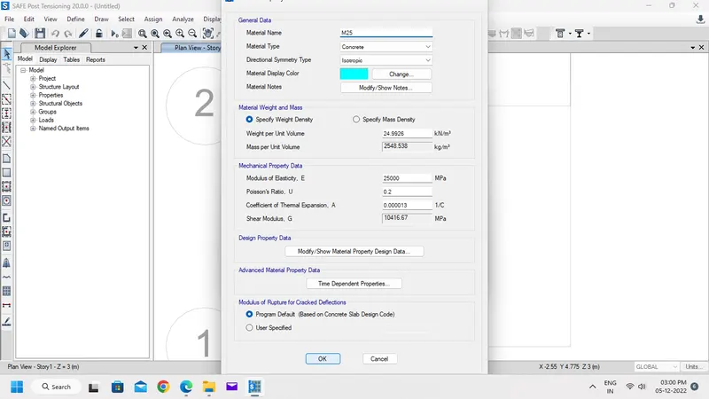
- Similarly define Rebar property as Fe500.
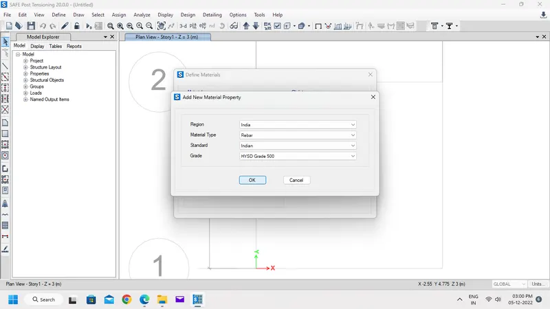
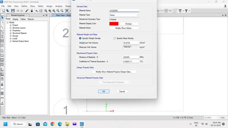
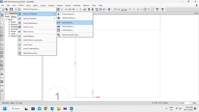
- Now Define Section properties, under Define Tab.
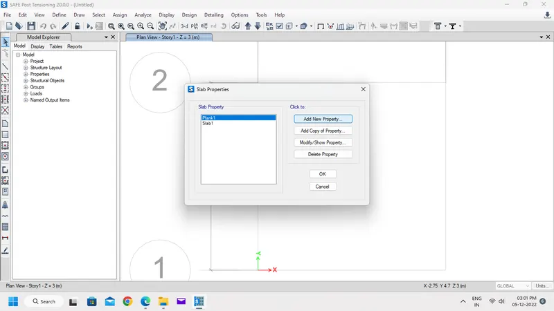
- A new window opens, Click Add New Property.
- Now define thickness and type for Pile cap as Mat type and Column & Pile as Stiff.
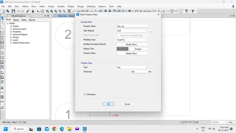
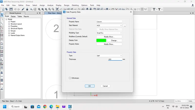
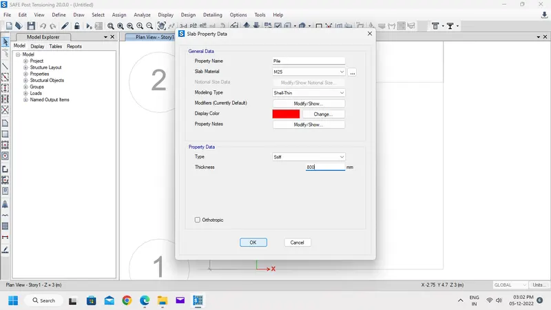
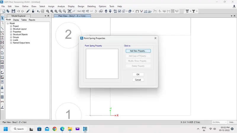
- In Define Tab, select Spring Properties and Point springs to define spring properties for Piles.
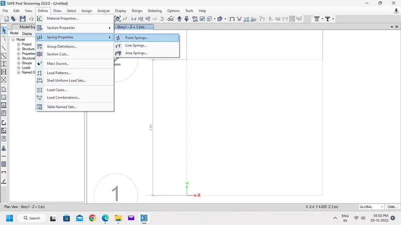
- Select Add New Property and define.
Step 4:-
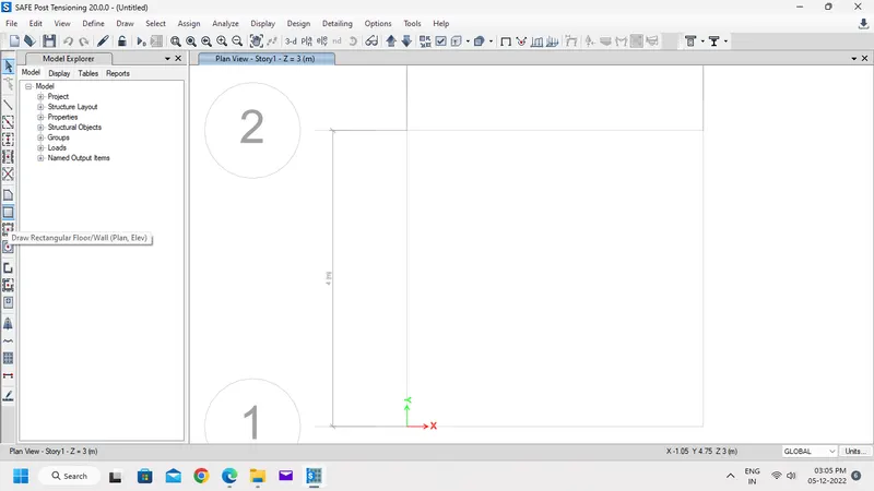
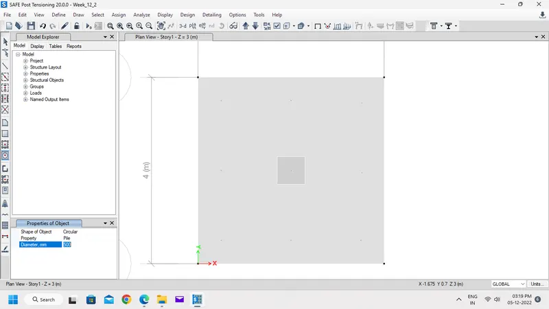
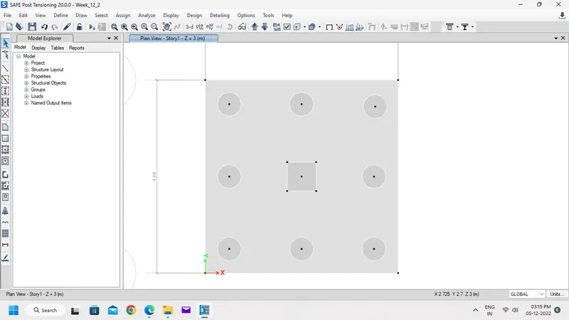
- Now draw the Pile Cap slab by clicking Draw Rectangular Floor/Wall icon.
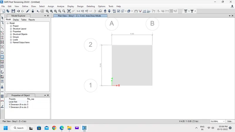
- Draw points and Place Pile & Column as Stiff element.
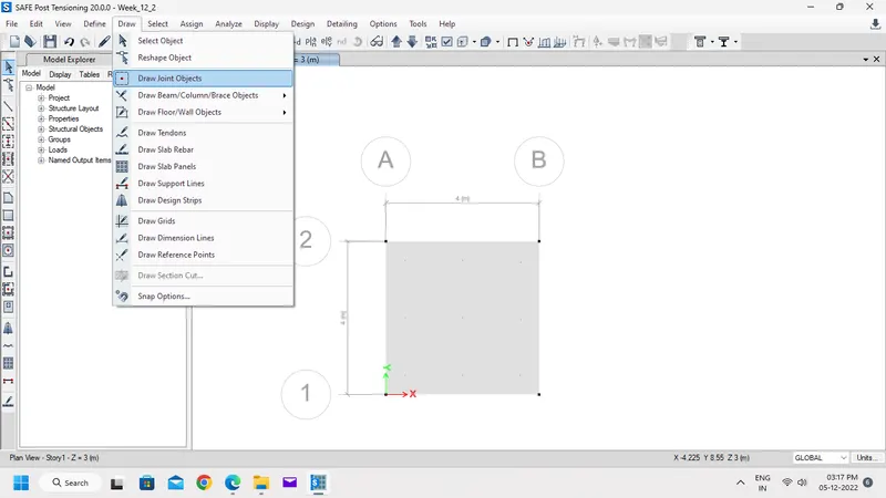
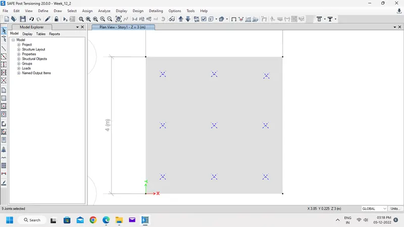
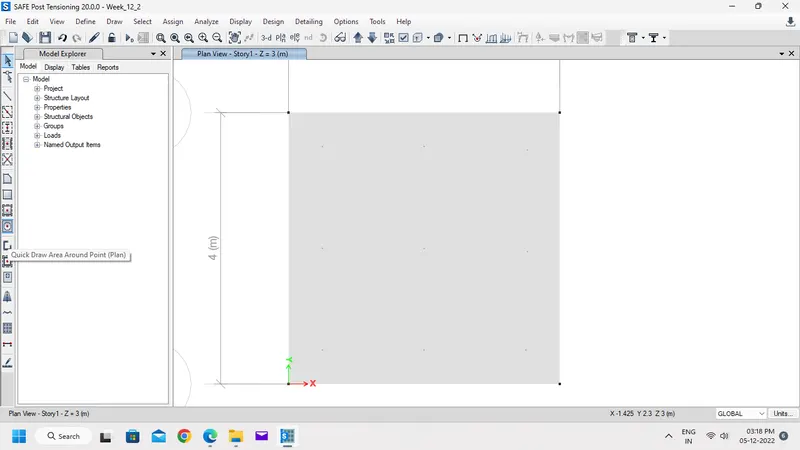
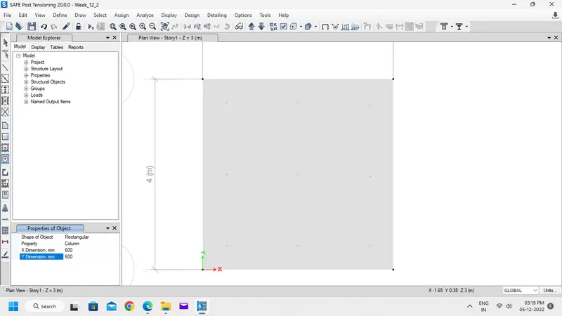
- Place the Pile and Column by clicking Quick Draw Area Around Point icon.
Step 5:-
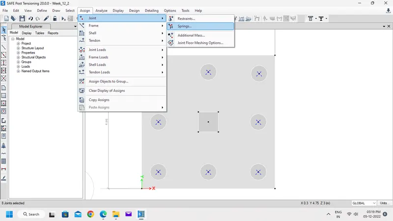
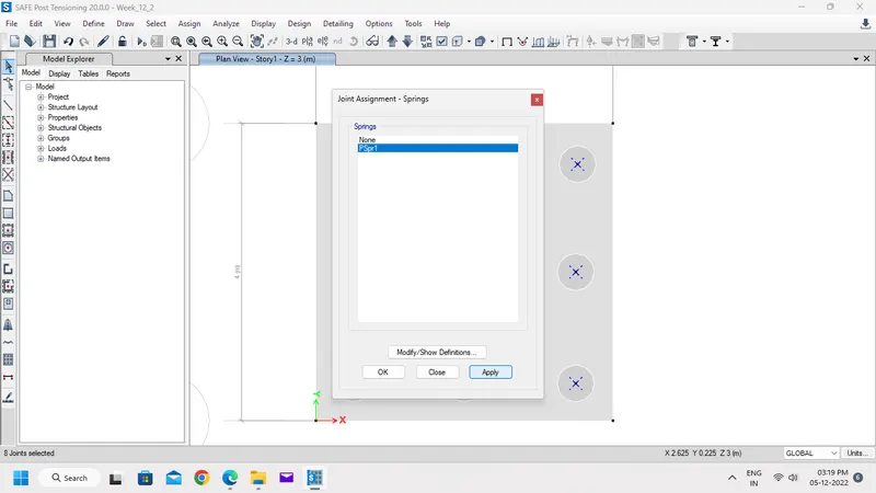
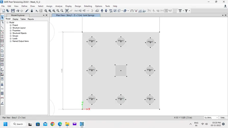
- Then Assign Springs at all Pile joints under Assign Tab.
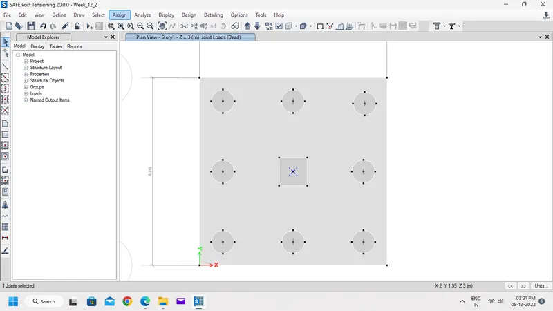
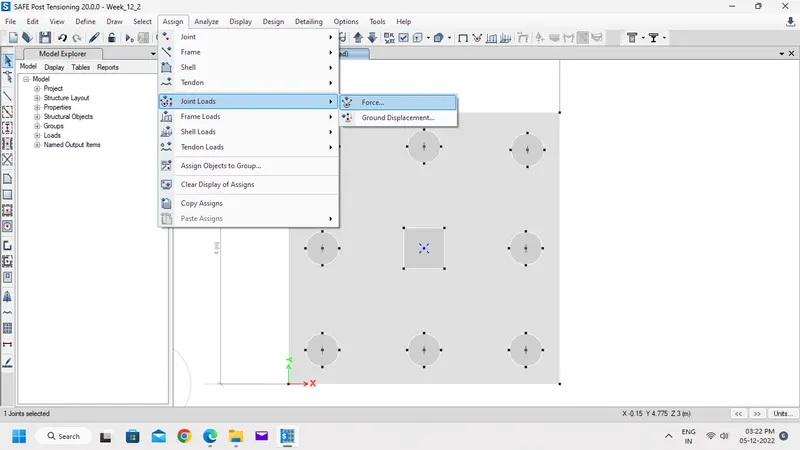
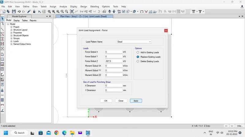
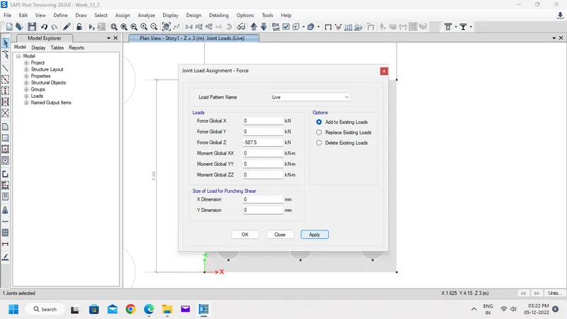
- Now select column joint and Assign Joint load from Assign Tab.
- Assign Dead and Live load each of 587.5 kN.
Step 6:-
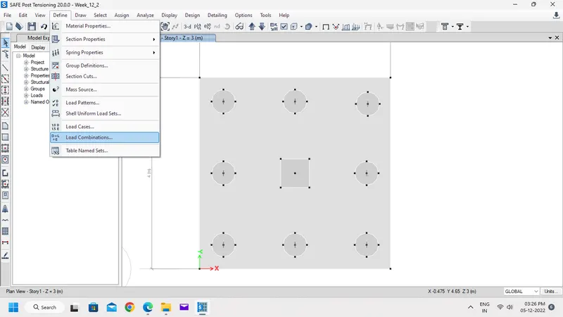
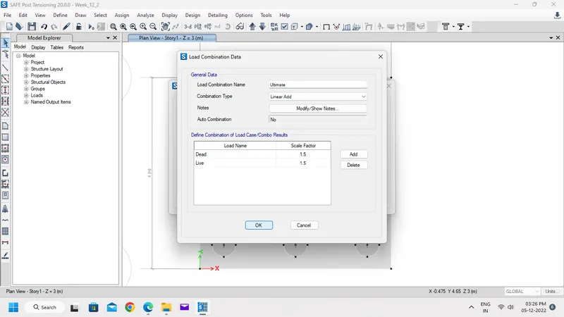
- Select Define Tab, click Load Combinations.
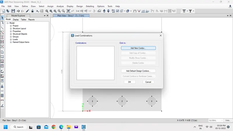
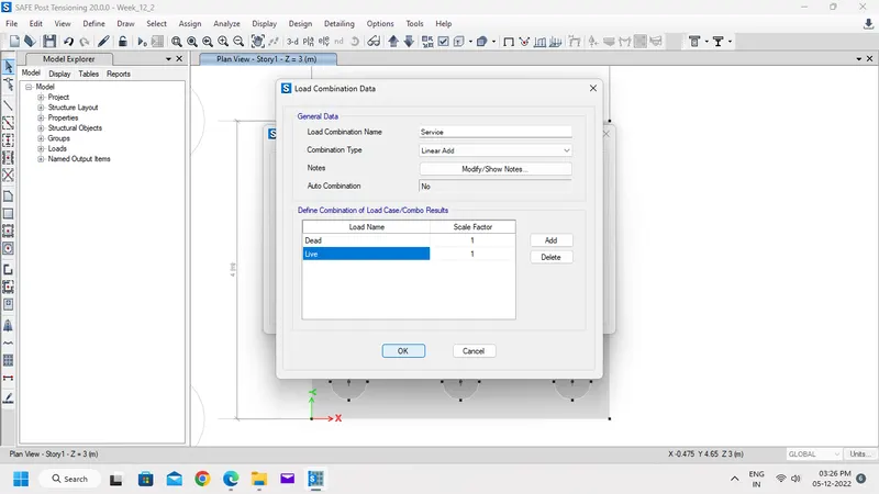
- Click Add New Combo and Add Service load combination (DL+LL) and Ultimate load combination (1.5DL+1.5LL).
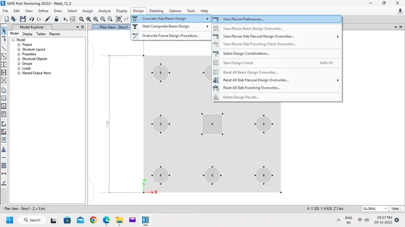
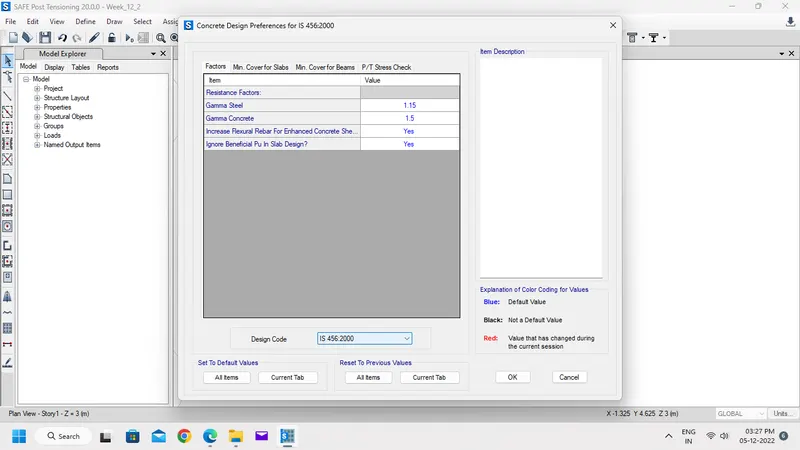
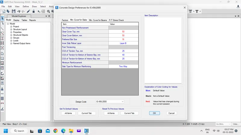
- Now Check the Design Preferences under Design Tab.
- Change the minimum cover to 50mm.
Step 7:-
- Select Draw Tab, click Draw Design Strips.
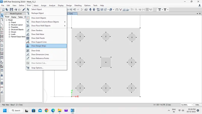
- Draw Strips A and Strips B along x and y directions.
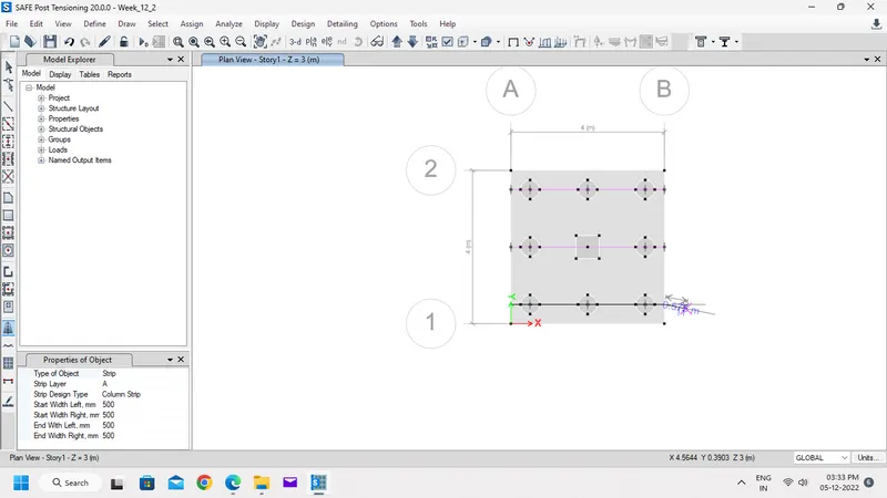
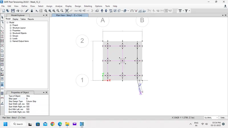
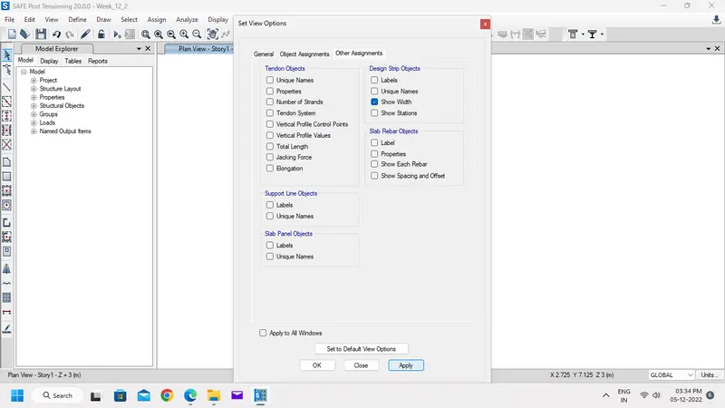
- Check whether the strips assigned well by check the show width.
Step 8:-
- Click Run Analysis, save the file before analysis.
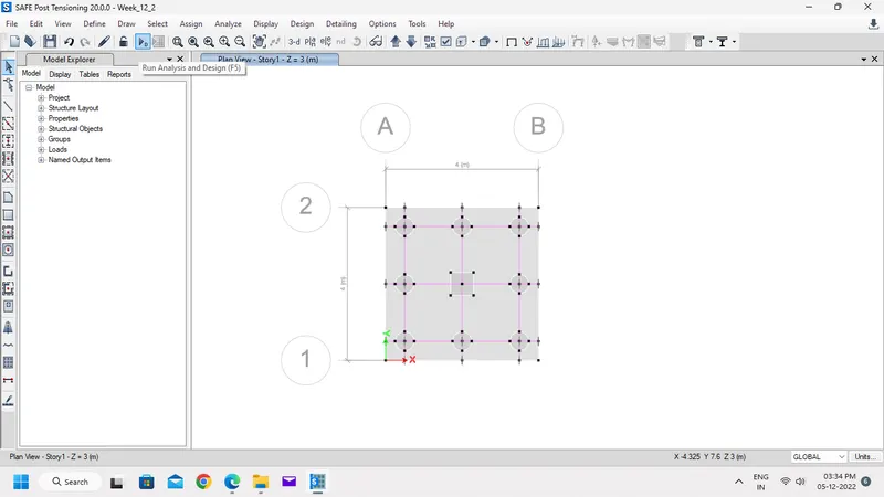
Checks need to be performed in SAFE Analysis:
- Individual Pile Capacity under Service load
- Settlement under Service load
- Two way shear check (Punching Shear)
- Flexural reinforcement design for Footing slab.
Step 9:-
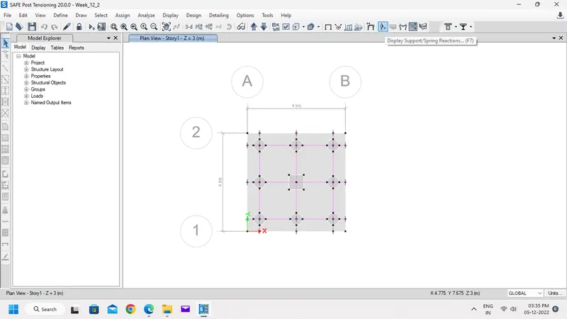
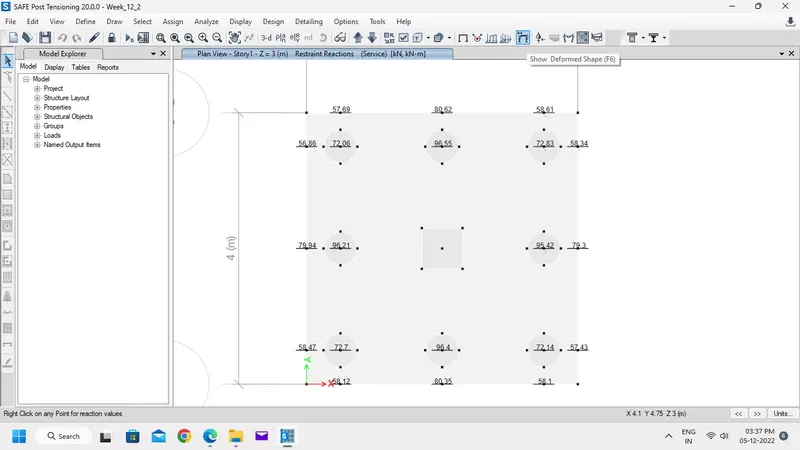
- Select Display Support/Spring Reactions for check Individual Pile Capacity under Service load combination.
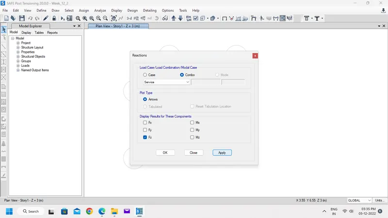
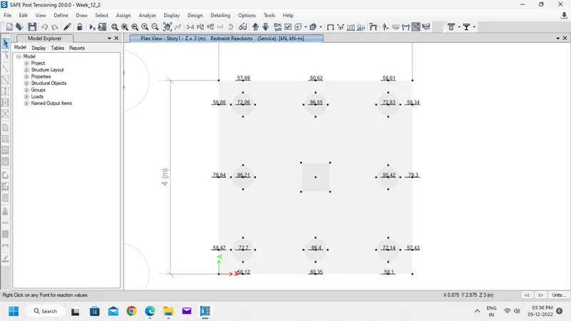
- Reactions at all pile is lesser than 200kN.
- Hence Safe.
Step 10:-
- Select Show Deformed Shape to see the displacment of slab under Service load.
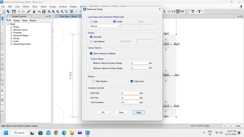
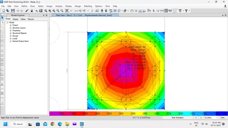
- Displacement of Pile cap is lesser than 50 mm.
- Hence Safe.
Step 11:-
- In Display Tab, select Show Punching Shear Design.
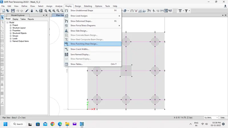
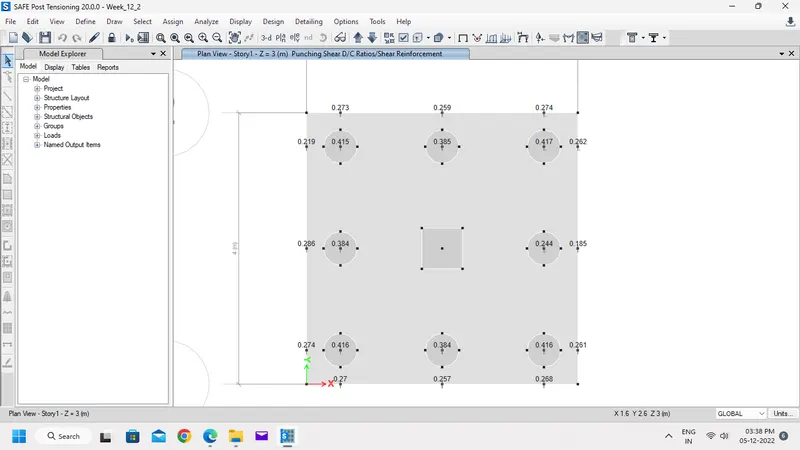
- Punching shear is lesser 1.
- Hence OK.
Step 12:-
- In Display tab, Select Show Slab Design and click strip based design.
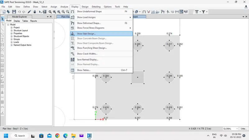
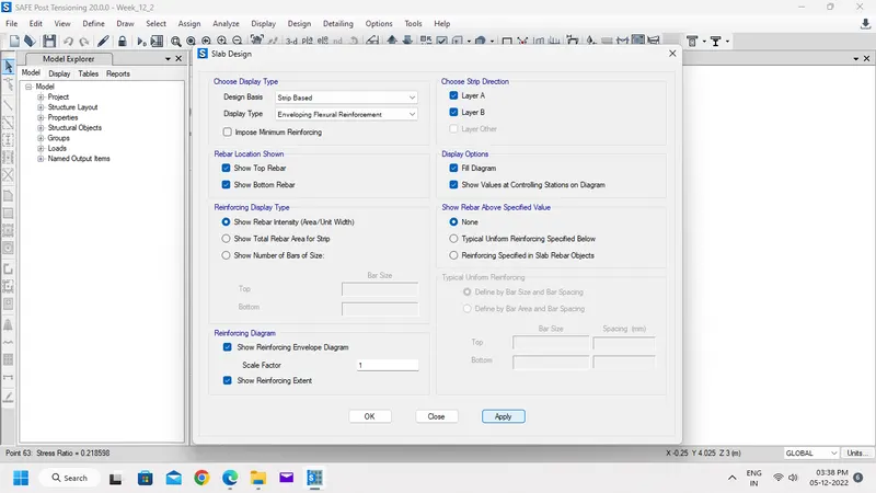
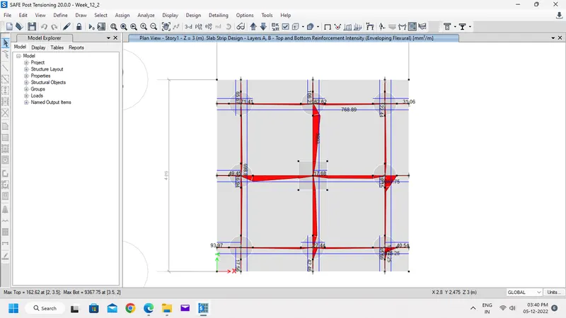
- Minimum reinforcement required for the pile is 3993 mm2.
- Hence provide 16mm dia rebar at 200mm spacing on both direction at bottom layer.
Result:-
- Analysis and Design of Pile Cap was done successfully.