Foundation Design using SAFE
AIM: Model the isolated footing provided in week 11 challenge on SAFE. Analyze and design it to verify the size, depth and steel provided as per calculations.
INTRODUCTION: SAFE is a computer program that is used to design high-rise floors and foundation slabs. Slab modelling, analysis, and design procedures use a wide range of sophisticated tools and applications.
PROCEDURE:
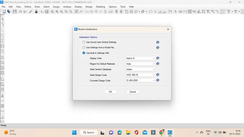
1. Double click on the SAFE software to open, once it is opened click on new model. A dialogue box shows up design codes are specified.
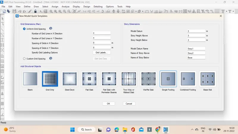
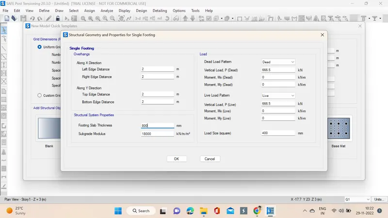
2. Another window popsup in which single footing is selected and the following data is filled as per the calculations.
- Subgrade Modulas = FOS*SBC / Max. Settlement = ( 3*150 ) / 0.05 = 9000 KN/m^3.
- The compression axial load for load combination (1.5DL + 1.5LL) is 2000KN.
- Unactored Load = 2000 / 1.5 = 1333.3 KN
- Dead load Breakup = 1333.3 / 2 = 666.5 KN
- Live load Breakup = 1333.3 / 2 = 666.5 KN
- So, Footing Thickness is 800mm.
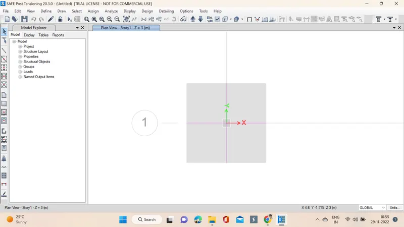
3. The data is enetered as per calculations and ok is clicked. A single footing is successfully placed.
4. Now go to Define -> Material properties and define the materials for the design M25 grade of concrete and HYSD500 rebar.
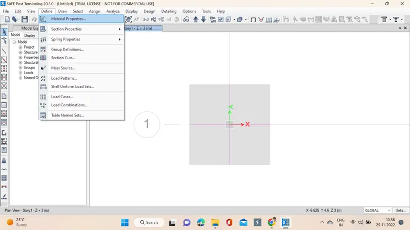
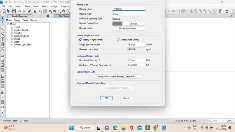

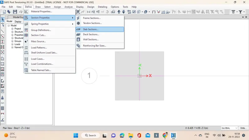
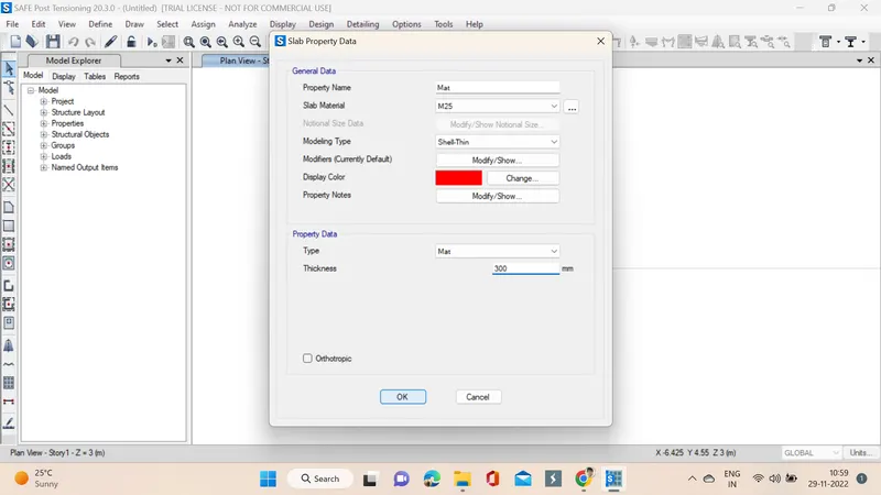
5. Now go to Define -> Section properties -> Slab sections and define mat slab of 300mm and stiff slab of 800mm of M25 grade concrete.
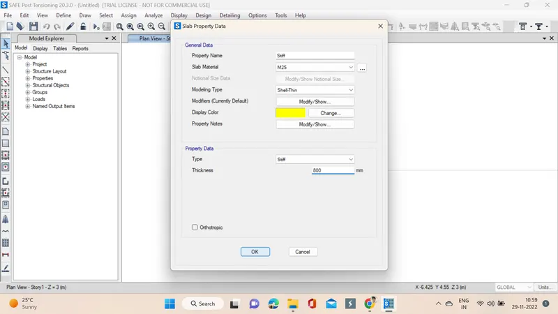
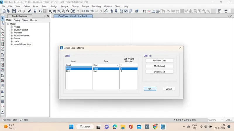
6. Define Load patterns
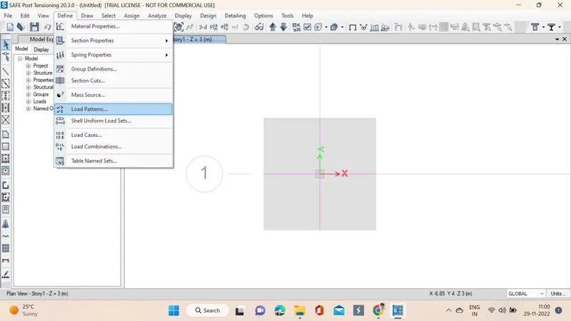
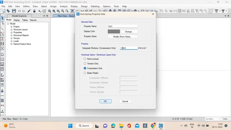
7. Define Soil Subgrade Modulas / Area spring Property Data.
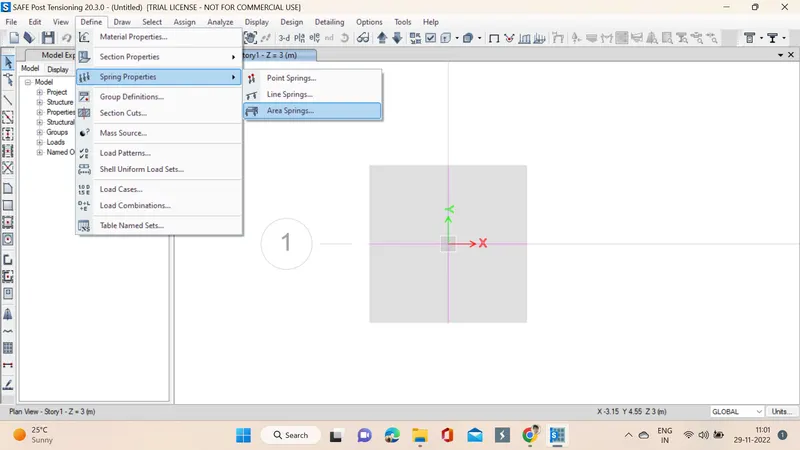
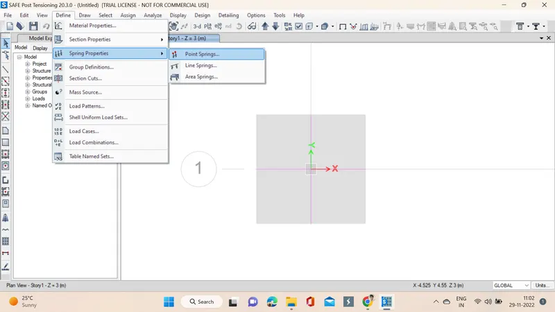
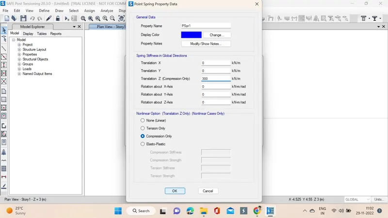
8. Define Soil Subgrade Modulas / Point spring Property Data.
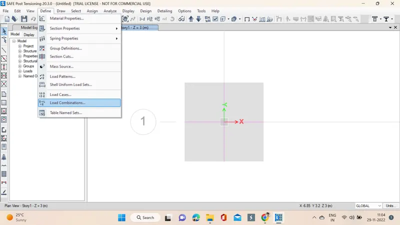
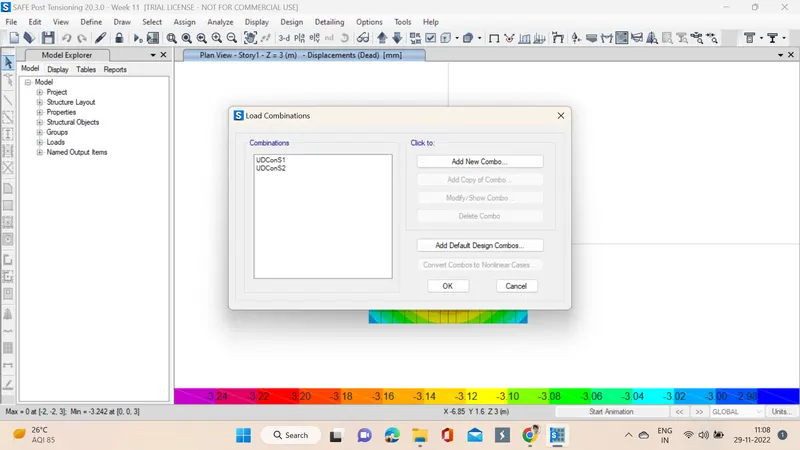
9. Load combinations are added.
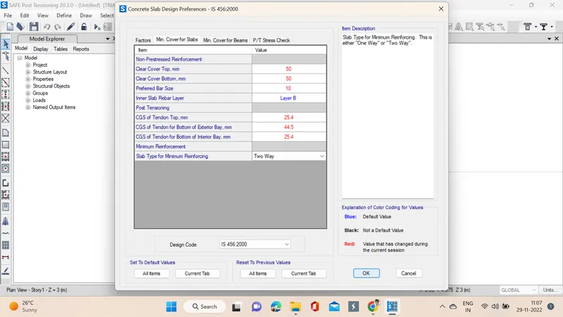
10. Go to Design -> Concrete Slab/Beam Design -> View/Revise preferences
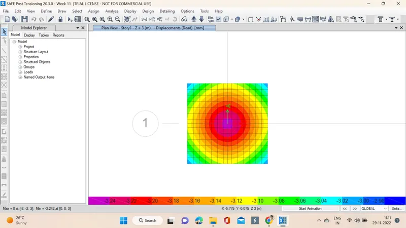
14. Analysis is runned successfully.
15. Checks
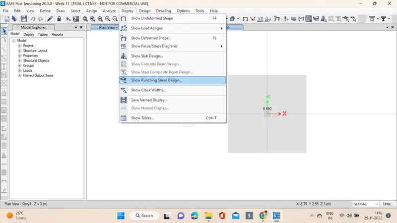
Deformed shape: Two-way shear:
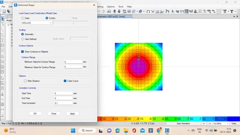
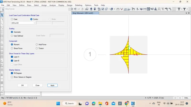
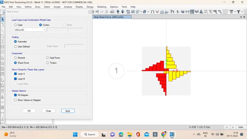
Bending moment: Shear force:
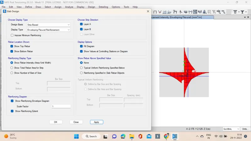
Flexural reinforcement design of footing slab:
RESULT: A model of the isolated footing provided in week 11 challenge is created using SAFE software and analyzed and designed it to verify the size, depth and steel provided as per calculations.
AIM: A column of size 600x600 carrying an unfactored gravity load (DL+LL) of 1175 KN is to be supported on pile cap, which ultimately transfers load to the piles underneath. Piles of 16 metres length and 500 mm diameter are to be used. Each pile has a load carrying capacity of 200 KN. Model, analyse and design the pile cap on SAFE to evaluate the following:
- Pile group to be used
- Depth of pile cap
- Longitudinal steel on top and bottom face in both directions
INTRODUCTION: SAFE is a computer program that is used to design high-rise floors and foundation slabs. Slab modelling, analysis, and design procedures use a wide range of sophisticated tools and applications.
PROCEDURE:
1. Given data:
Column size = 600 X 600mm
Factored load = 1175 KN
Pile length = 16 m
Pile Diameter = 500 mm
Load carrying capacity = 200 KN
Calculations:
i] Number of Piles = 1175 / 200
= 6 Piles
ii] Spring Constant = E*A / L
= 25000* 196375 / 16000
= 306835 N/mm.
Edge spacing is taken as 200 or 300 mm.
2. Double click on the SAFE software to open, once it is opened click on new model. A dialogue box shows up design codes are specified.
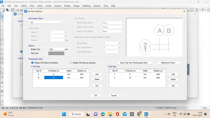
2. Another window popsup in which grid only is selected and the following data is filled as 3.2 and 2.
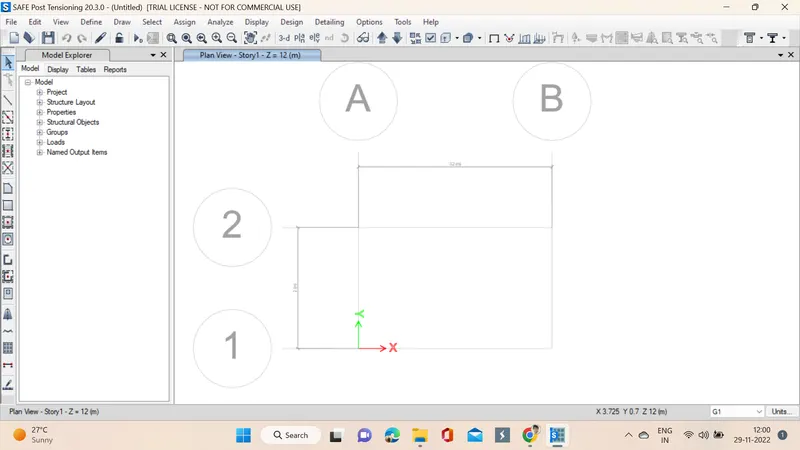
3. Then ok is clicked and then this is how the plan view looks.
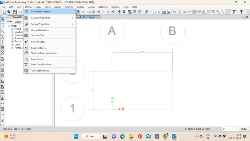
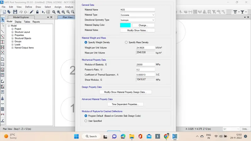
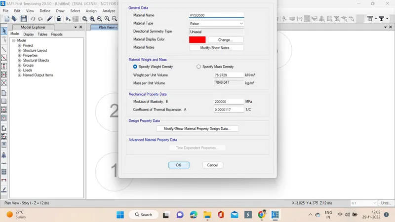
4. Now go to Define -> Material properties and define the materials for the design M25 grade of concrete and HYSD500 rebar.
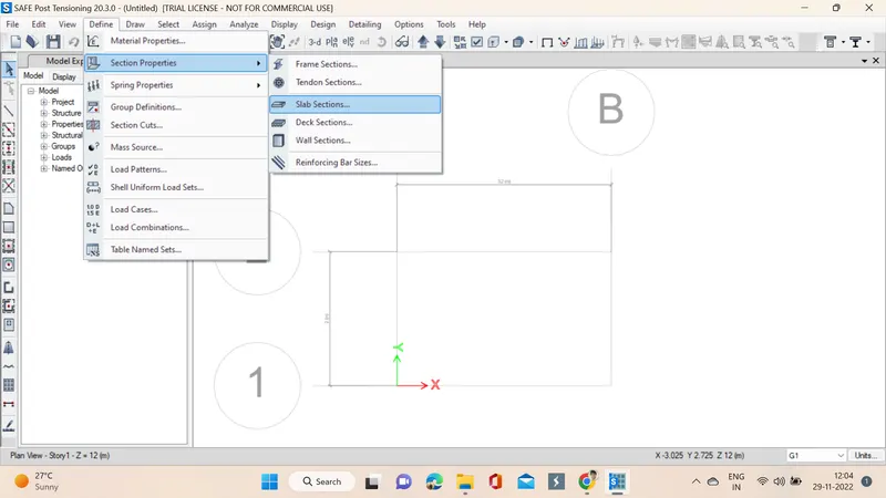
5. Now go to Define -> Section properties -> Slab sections and define mat slab of 300mm and stiff slab of 800mm of M25 grade concrete.
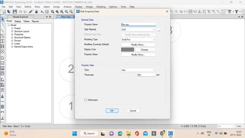
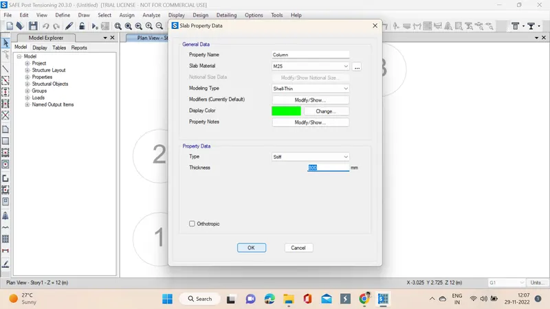
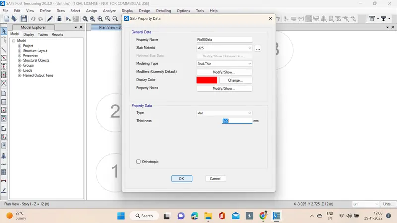
6. Draw the slab from Quick draw Slabs.
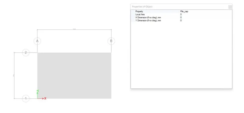
7. Add piles at the Points. Modify edge distance to 0.2m.
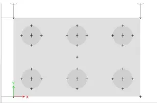
8. Create a column of 600X600mm. Draw the cloumn in the center.
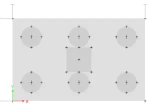
9. Spring were added. Define spring Property data.
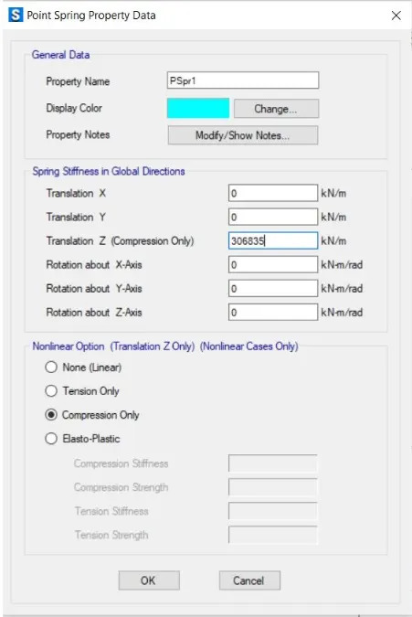
10. Select Pile -> Assign -> Support Data -> Point Springs. Spring Constant is taken from above calculation. Dead load and Live Loads are 587.5 KN.
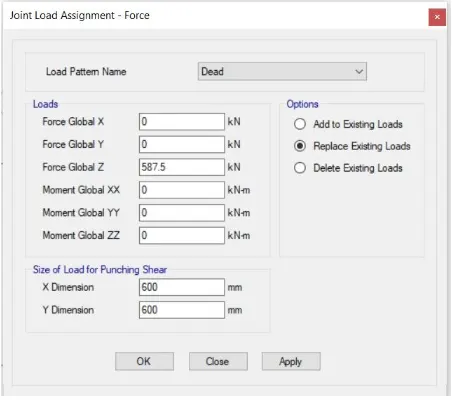
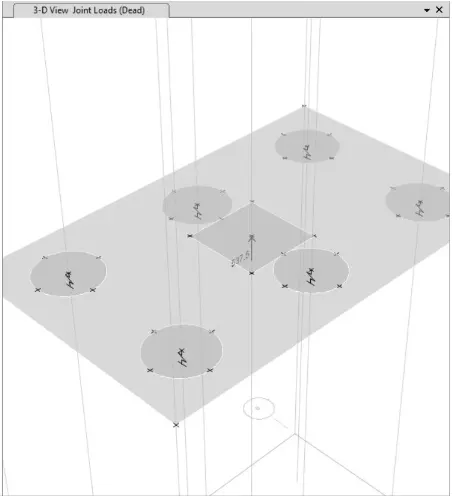
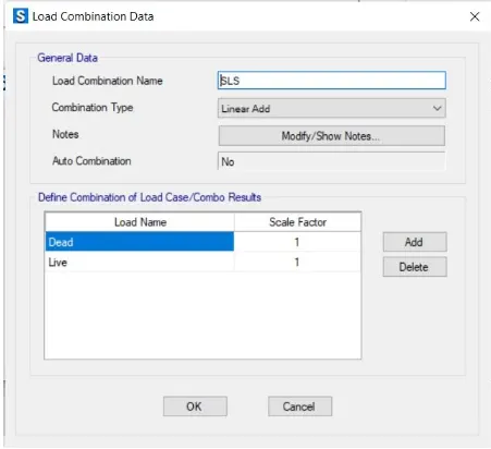
11. Load Case combination was defined Next.
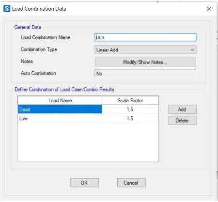
12. Analyse the model using analyse option then click on check model the modelled structure is verified without errors and warnings.

13. The model is analyzed Successfully.
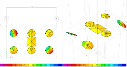
14. Maximum displacements are found safe. All the punching shear values ar less than 1.
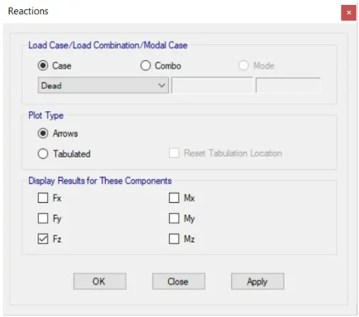
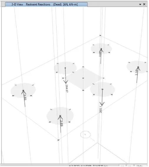
15. Joint reaction diagram, as all the reaction force are according to limit.
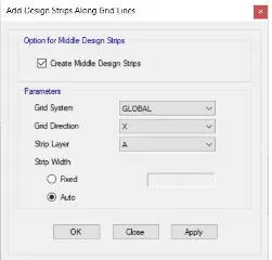
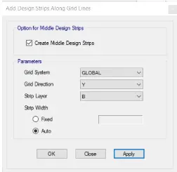
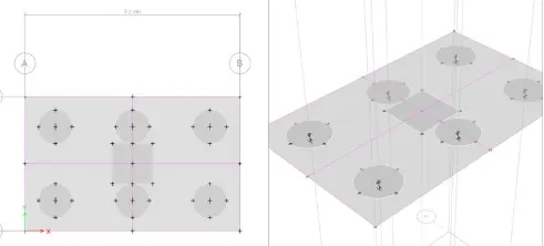
16. Reinforcement details are added next.
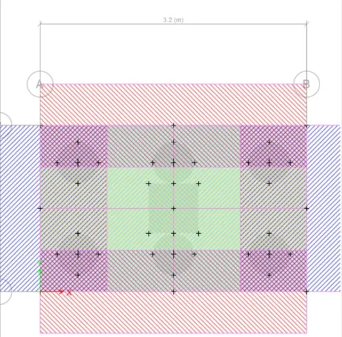
17. Run analysis again.
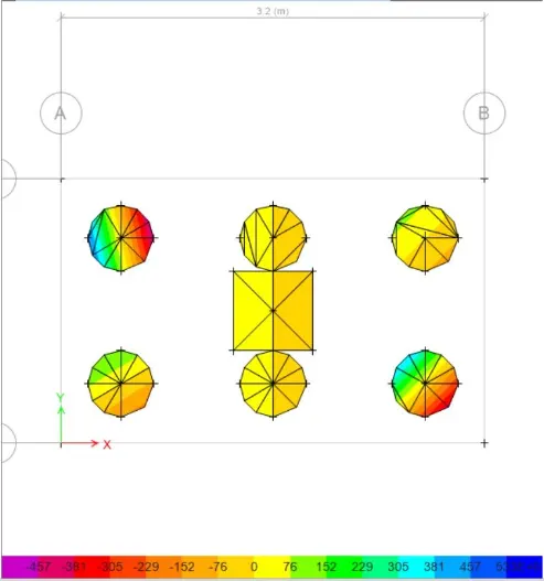
Reinforcement Slab Design:
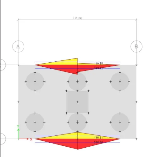
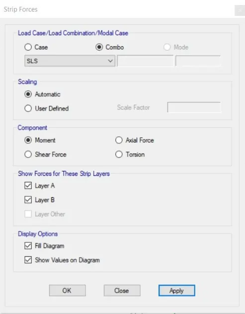
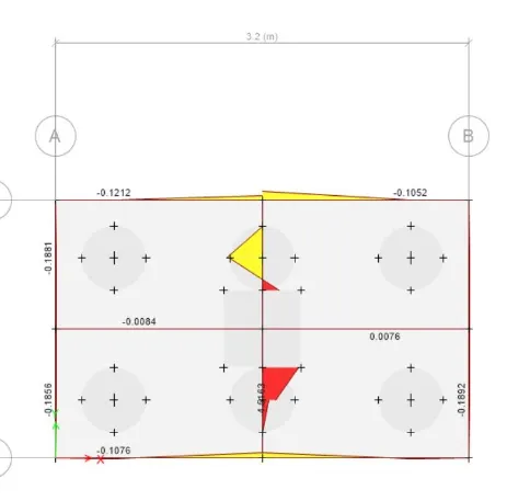
Bending Moment:
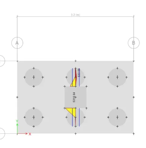
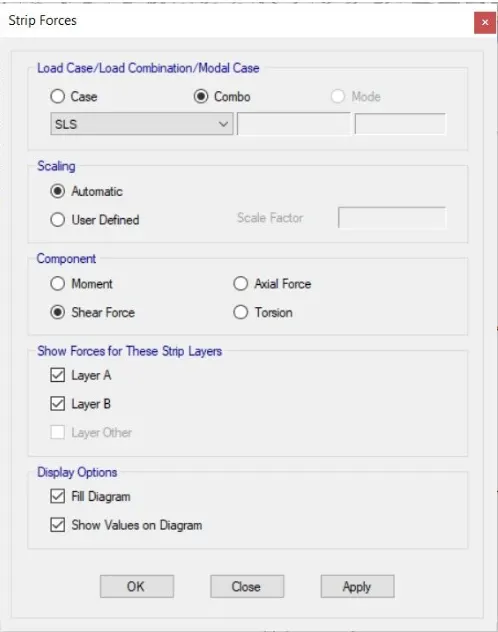
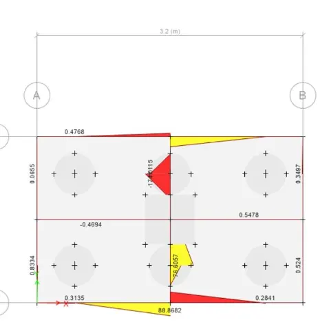
Shear Force:
RESULT: A model is created, analysed and designed the pile cap using SAFE software to evaluate Pile group to be used, Depth of pile cap, Longitudinal steel on top and bottom face in both directions.