Foundation Design using SAFE
1.
Aim
To design a Isolated footing for a column size 400 x 400 by using SAFE. Use all the data’s given for Challenge 11.
Given Data
Axial compression Load of 1.5DL + 1.5 LL is 2000KN.
Safe Bearing Capacity is 150KN/m2 @ 2m Depth
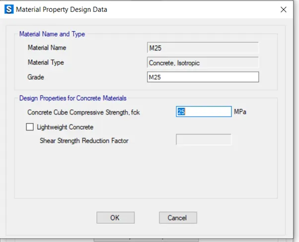
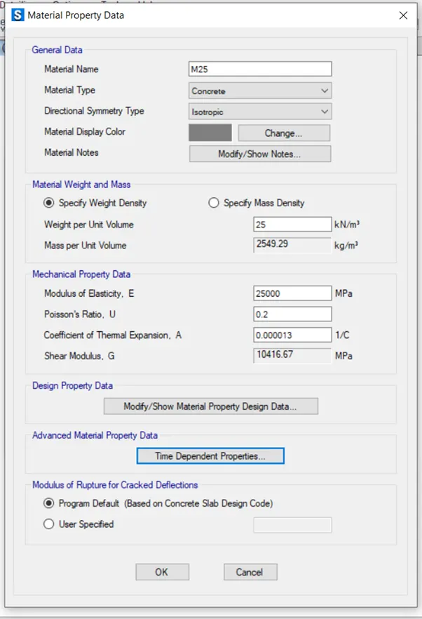
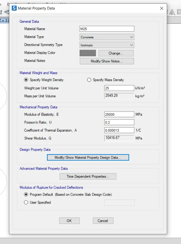
Grade of Concrete M25
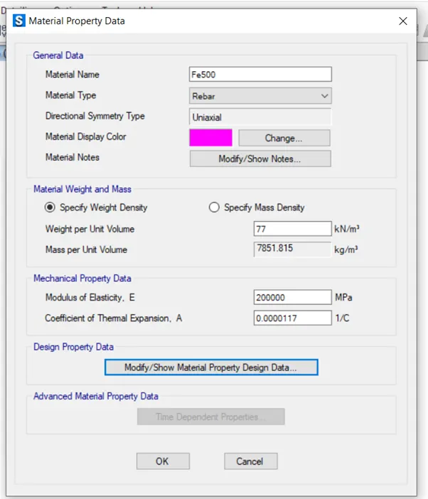
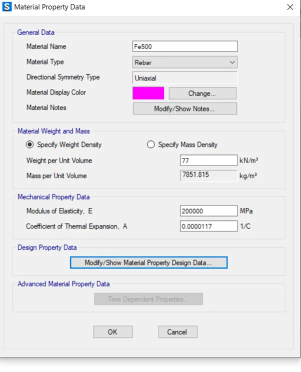
Grade of Steel Fe 500
Let us Take
Unfactored Load = Factored Load /1.5
= 2000/1.5 = 1333.3 KN This load is Combination of Both DL and LL
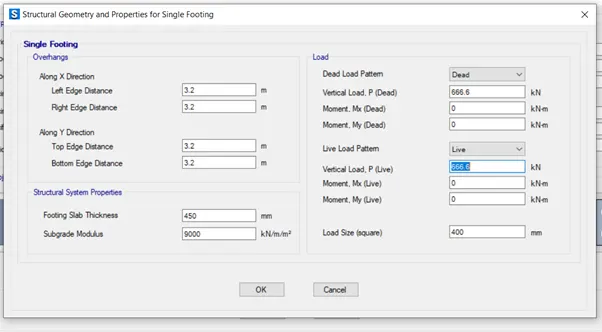
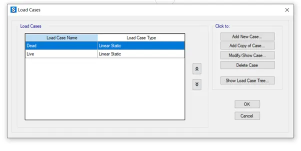
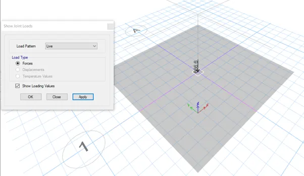
Dead Load = 1333.3 /2 = 666.6 KN
Live Load = 666.6 KN
Yield Strength Fy = 500 N/mm2
Tensile Strength = 545 N/mm2
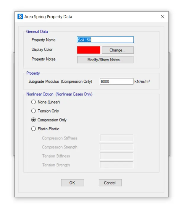
Soil Subgrade = (FOS x SBC) / Permissible Settlement
FOS = 3 SBC = 150KN/m2 Settlement = 50mm for Isolated footing as Per IS 456
Soil Subgrade = (3 x 150) / 0.05 = 9000KN/m2
Modulus of Elasticity = 5000 x Sqroot Fck = 25000 N/mm2
Procedure
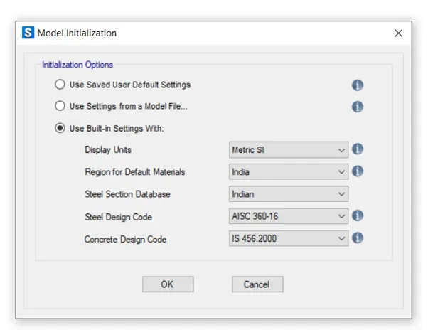
- Open the safe software and click on New and select Code book as IS 456 2000 and Unis as Metric.
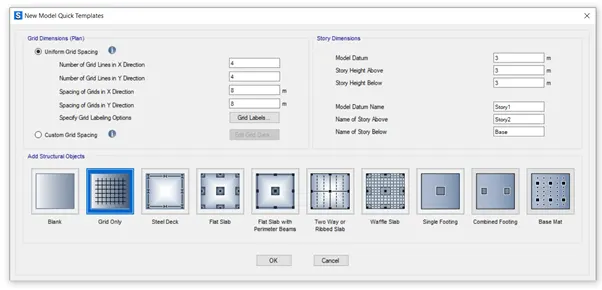
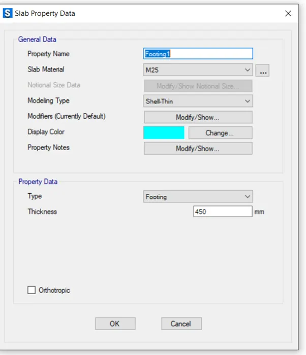
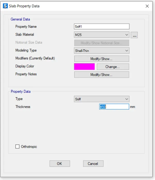
- Use Single footing template and give the side of footing and size of column, Dead load, Live load and soil Properties etc.
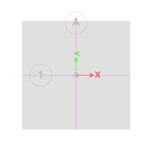
- Then Press ok. The geometry of the footing will be created.
- Check the Material assigned are correct or not if not then change it.
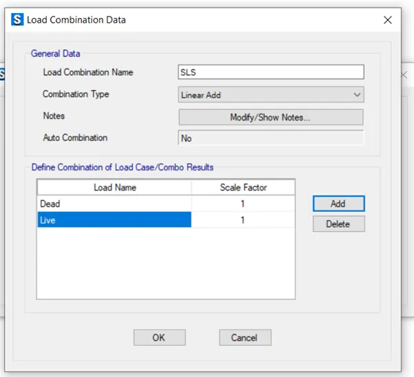
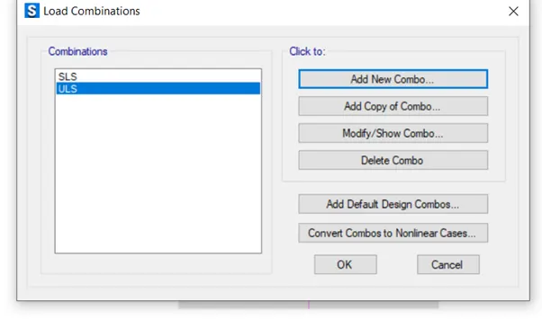
- Then check the load is applied and the load combinations are generated.
- Check the soil property is assigned.
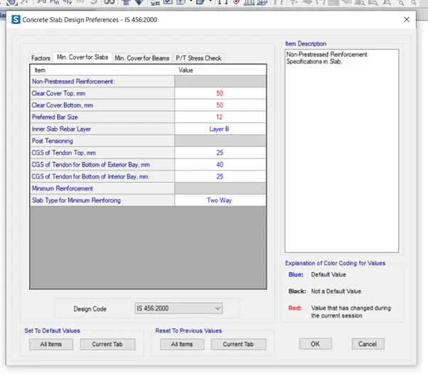
- Once all done hen check design preferences and check the model for any errors.
- Then run the analysis.
- Check the results if it fails the change the depth of footing and rerun the analysis.
Input
Output and Result
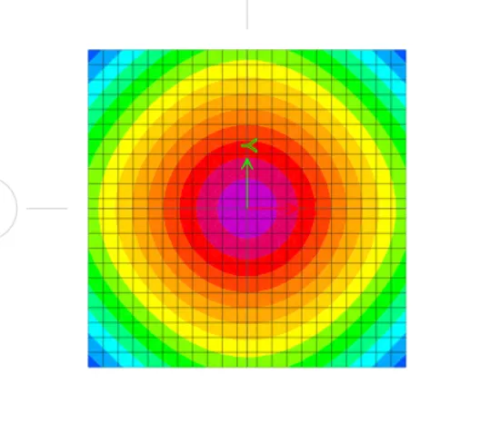
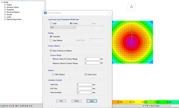
The maximum deformation at the column is abut -6.3 Hence ok.
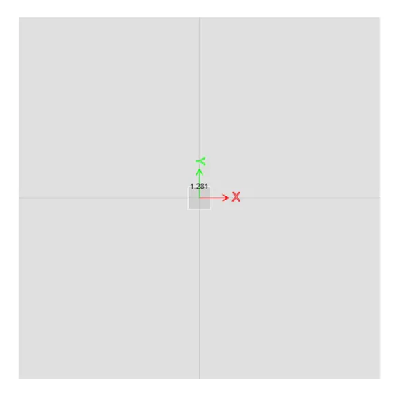
For Punching shear our design is failed. Hence we Increase the Depth of footing and re run the analysis.
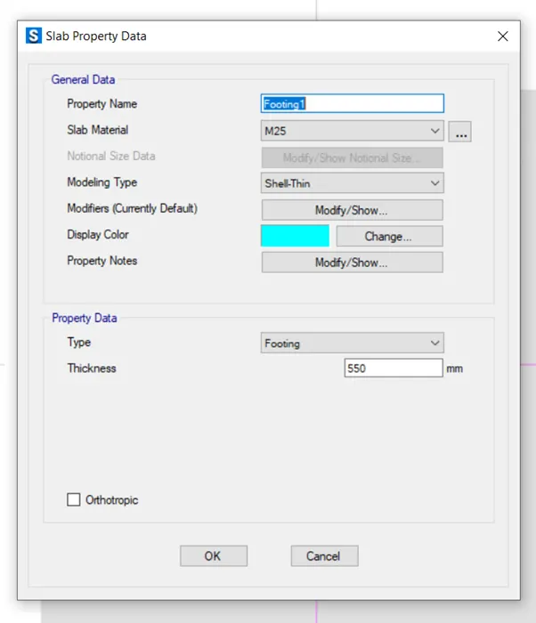
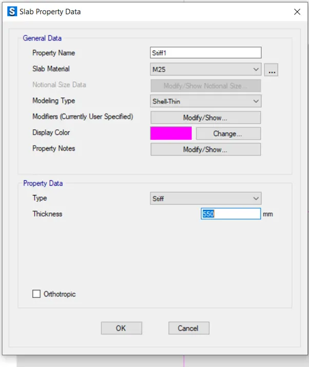
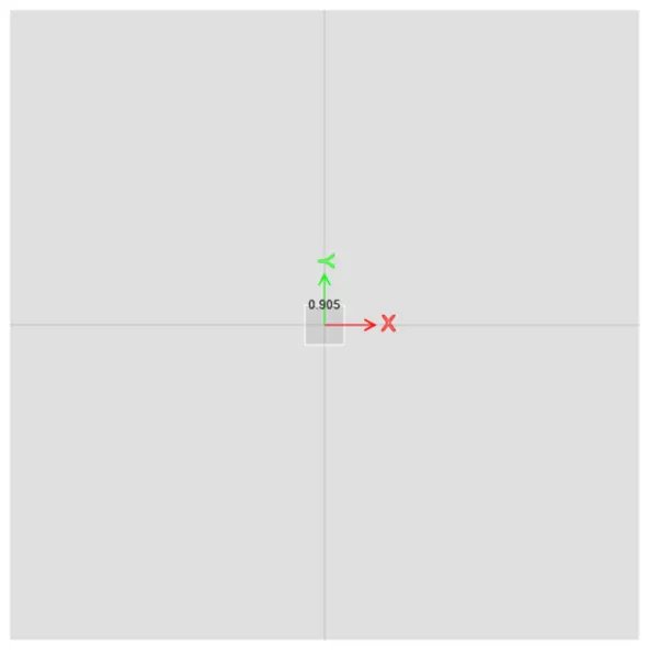
Our Punching Shear is 0.9 which is les than 1 Hence ok.
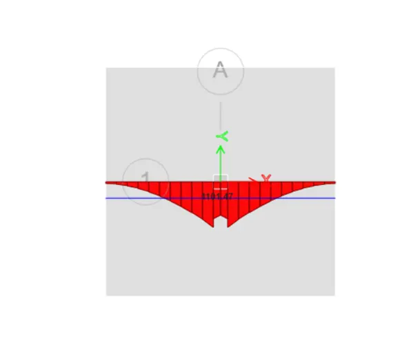
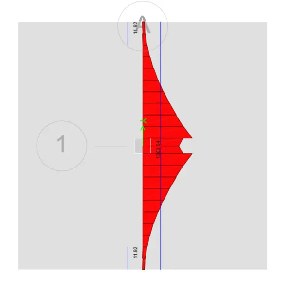
Thus, The Maximum Reinforcement in X direction is 1101.47mm2/m
i.e 12mm Dia at 100mm Spacing
Maximum Reinforcement in Y direction is 1363.54mm2/m
i.e 16mm Dia at 150mm Spacing
2.
Aim
To Design a Pile Foundation By using SAFE.
To evaluate the Pile Group to be used,
Depth of Pile Cap,
Longitudinal Reinforcement on top and Bottom.
Given Data
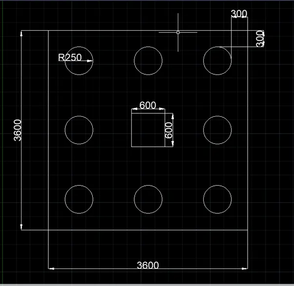
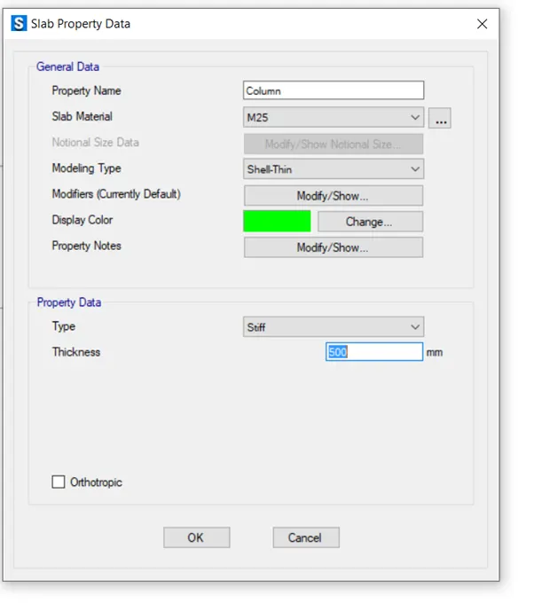
Column 600 x 600
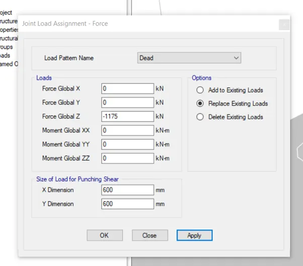
Unfacotred Load (DL + LL) = 1175 KN
Length of Pile = 16mtr
Diameter of Pile = 500mm
Load Carrying Capacity of Pile = 200KN
Let Us Take
Number of Piles = Unfactered Load + 10% Self Weight / Pile Capacity
= (1175 +117.5) /200
= 6.46
Let Us consider 8 No of Piles for Symmetrical purpose.
Spring Constant = A x E / L
Area of pile = (500 x500 x 3.14) / 4
= 196250 mm2
Length of Pile = 16000mm
Modulus of Elasticity = 25000 N/mm2
Spring Constant = (25000 x 196250) / 16000
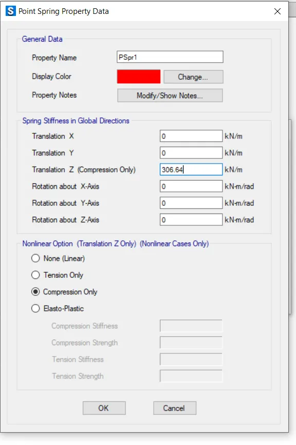
= 306640.6 KN/m or 306.64 KN/mm
Distance between Piles = 2.5 times Dia of Pile
= 2.5 x 500 = 1250mm
Distance form Pile cap edge to Pile is 300mm
Yield strength = 500 N/mm2
Tensile Strength = 545 N/mm2
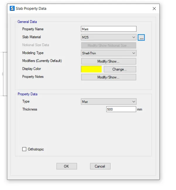
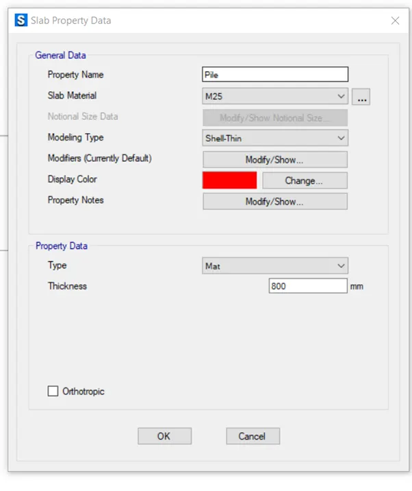
Let’s Assume the depth of Pile as 500mm
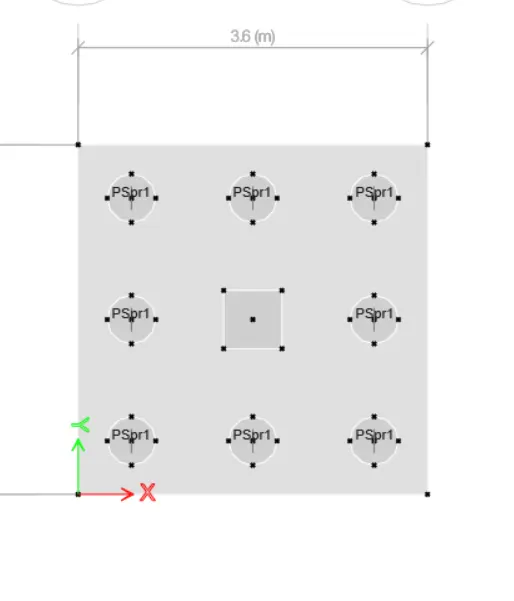
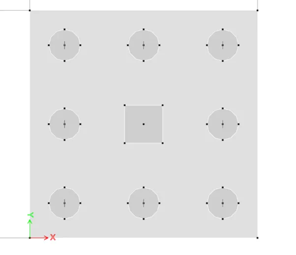
Arrangement of Piles
Procedure
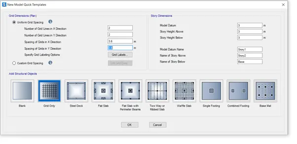
- Open the new file and give the codes and units as per Indian Standard.
- Then give grids. Define material properties and then section properties for Column, Pile Cap and Piles.
- Draw pile cap with the grids.
- Then create reference points for piles and column.
- Then create piles and columns with the help of reference points.
- Then define the spring constant and assign it to the piles.
- Define dead load and live load and assign it to Column.
- Then create load combinations.
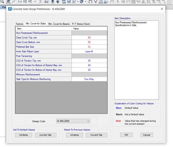
- Check design preferences.
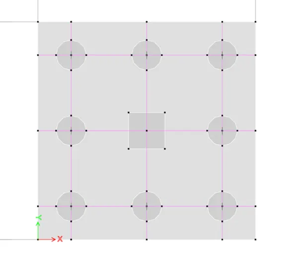
- Draw design strips.
- Then run the analysis.
- Make all necessary checks and if any failure occurs, then make necessary changes and rerun the analysis.
Input
Add Strips
Then Run the Analysis
Output & Result
Check for Deformed Shape
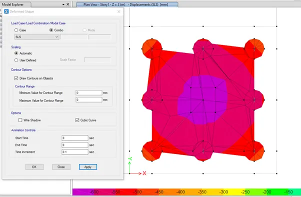
The values are Less than 1 Hence Ok
Then Check for Punching Shear
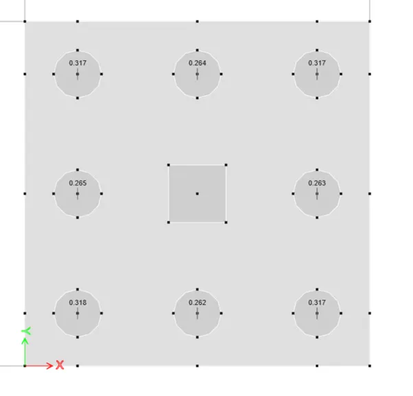
This also OK
Then check for reaction
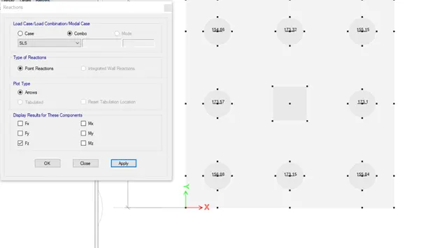
Our Pile capacity is less than the Actual Pile Capacity Hence Ok.
Then check for Flexural Reinforcement
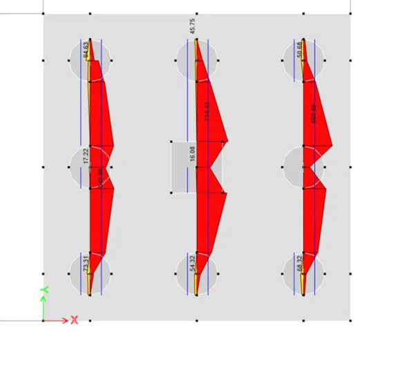
The Maximum Bottom is 714.43mm2/m
Hence we can use 12mm Dia at 150mm c/c
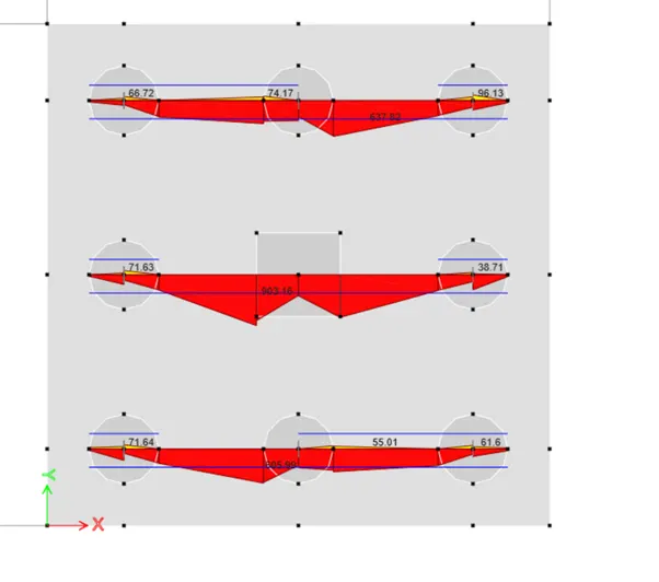
The maximum Bottom Reinforcement is 903.16mm2/m
Hence we can use 12mm Dia at 125mm c/c.